SUMMARIZING EMBEDDED EXECUTION TRACES THROUGH A COMPACT VIEW Carlos Prada-Rojas∗ , Miguel Santana, Serge De-Paoli, Xavier Raynaud STMicroelectronics 850, rue Jean Monnet, 38921 Crolles Cedex, France Email:
[email protected] ABSTRACT Execution traces are becoming a highly appreciated method to debug and analyze software programs, especially in the areas of embedded systems and high-performance parallel computing. However, execution traces can result in enormous volumes of data, making them difficult to manage and exploit. In this paper, we describe a graphical solution to help the user navigate such large traces, in order to localize the points of interest for the analysis. Keywords: Execution traces; Debug; Trace Analysis; Embedded Software; Embedded Software Analysis; Outline View 1. INTRODUCTION Execution traces are becoming a highly appreciated method to debug and analyze software programs, especially in the areas of embedded systems and high-performance parallel computing. They provide the ability to analyze execution issues but also to optimize the behaviour of an application while in realtime conditions. They are of particular interest when dealing with multiprocessor platforms executing complex software applications, such as set top-boxes, mobile phones, multimedia devices, but also highly parallel applications. Many new factors appear in those cases, or become more important than conventional applications: multiple execution flows, asynchronous operations, real-time constraints, shared and local memories, etc. Traces allow the analysis of the details of an execution to better understand the roots of functional or performance issues. Interactions between the components of an application often depend on the precise timing of their execution. Bugs related to such interactions are difficult to understand and resolve. Moreover they have a tendency to disappear when using standard debugging tools (Heisenbugs) and so become difficult to reproduce [1]. Indeed many debuggers are highly intrusive and can seriously impact the timing of an application. However, traces are much less intrusive and rarely impact real-time conditions. Furthermore, modern hardware traces mechanisms [2] allow keeping intrusiveness under control. ∗
Supported by a CIFRE STMicroelectronics industrial grant
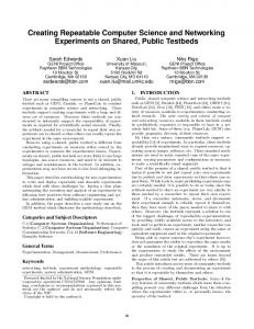
Unfortunately execution traces can quickly reach huge volumes of data and pose a problem of scalability [3]. The volume depends both on the number of events being collected during the execution as well as on the duration of the trace collection. The first scalability issue appears with trace files, as they can be composed of many files and be very big. If this problem is solved, there remain two other scalability issues to manage: the visualization and the analysis of such a volume of trace data. End-users can be easily overwhelmed by the quantity of information available in a detailed trace. Our OutlineView aims to simplify the navigation of big volumes of traces, through a compact view. Such a view gives a summary of the execution traces from a given perspective, chosen by the end-user. An OutlineView is close to an Information Mural [4], used as an entry point for the analysis of a trace. It allows the easily identification of peaks and troughs, but also some other potentially interesting patterns for the analysis: hotspots, missed deadlines, unbalanced resources, etc. Furthermore, it is directly connected to analysis tools; a simple click on a point of the OutlineView opens the associated analysis tool on the corresponding trace spot. In this paper, we first introduce the trace management framework where these compact views are available, before describing them in detail and showing the added value they bring through two case studies. Then we depict related works on large trace analysis and visualization. And we finish the paper by concluding and sketching future directions for the OutlineView. 2. TRACE MANAGEMENT FLOW Collecting execution traces involves different actors working through different phases, as illustrated by Figure 1 for embedded systems: • Trace generation either through software instrumentation or hardware mechanisms in the embedded system side. • Trace transport through a hardware trace probe if using a trace port.
• Trace collection on the workstation side, through a trace server or standard file mechanisms (e.g. remote mount). • Trace analysis of collected trace files.
Fig. 2. Trace Database Layer
Fig. 1. Trace Management Flow for Embedded Systems Our OutlineView intervenes in the last phase when the trace collection is finished and ready to be exploited. In our case, we regroup all trace files into a trace database using a generic trace format, able to manage different environments and cases (e.g. OS and/or application traces). The database layer provides different services to analysis tools, as illustrated by Figure 2: persistence, query, search, filtering and communication. Database traces are created by specific decoders responsible for the conversion between specific trace formats and our generic format, and for feeding the database. In the other hand, they are used by all analysis tools, from simple ones (e.g. a command line reader or a straight trace viewer) until sophisticated ones (e.g. LTTng Viewer [5] or a Componentbased System Analysis approach [6]). An OutlineView works on top of such a database and communicates with other analysis tools through database services. 3. THE OUTLINEVIEW The OutlineView is a graphical tool aiming to provide trace users with a compact view of a set of execution traces. Such a view is a miniature representation of the traces giving a global view of the information carried by them. It allows the quick identification of items of interest and so the user can focus on their analysis. Thus the tool can be viewed as a navigational aid, used as an entry point for more detailed analysis views and providing help to look for interesting patterns or to examine the traces from different angles. The OutlineView is an integral part of the set of analysis tools provided by our trace management framework. It takes
as input a trace database and a set of parameters selected by the user. It builds and provides then an interactive graphical view showing a global overview of the trace corresponding to the selected parameters. The user can navigate over the view to get more information but also to jump to other more detailed associated views through a simple click. Using an OutlineView is done in three different phases: 1. Selecting the trace events to consider on the global overview 2. Selecting the functions to apply to the selected events 3. Displaying and analyzing the resulting view These three phases are described in the following sections. 3.1. Selecting Trace Events An outline view is built around a small number of categories of trace events. It aims to focus on the key components of a trace, in order to reduce noise and to focus the analysis on what it is really important for the user. Such components are selected by the user and are what we call an angle or a viewpoint for the analysis. It is however important to notice than an outline view is built all along the time axis. So the first step to build an OutlineView is to select the categories of events or parameters composing the angle of analysis desired by the user. 3.2. Selecting Analysis Functions Compressing the selected events of the trace over the time axis can be done using different analysis functions, going from simple compression to very complex computing functions. The OutlineView provides a set of predefined functions covering the most common needs: sum, average, ratio, count, etc. But it also provides the capability to define user specific functions. Selecting and/or combining the analysis functions allows the user to get interesting points of view: workload, event
frequencies, processing delays, etc. It is the second step in order to build an OutlineView.
values are stored, along with their timestamps, in an n length array.
3.3. Displaying an Outline View The third phase is automatic and starts as soon as the previous steps are complete. Data for the OutlineView is extracted from the trace database and processed using the selected analysis functions, in order to build a graphical view showing the results. Figure 3 gives an example of an OutlineView result. This view is interactive and provides different features to better explore the selected angle of analysis. Moreover it can be connected and synchronized with other analysis tools in order to get a zoom and more completed view of a focus chosen from the outline view. 4. CASE STUDIES The following sections illustrate OutlineView features by means of two case studies. The first one corresponds to the analysis of the use of the processors of an SMP platform, whilst the second one corresponds to the verification of timing constraints for a video-decoding task. 4.1. Improving Load Balancing on an Embedded SMP Platform Load balancing between the processors of an SMP platform is generally done automatically by the operating system. However such a balancing is not always optimal for a given application. Some embedded applications are the kernel of an embedded system, and so need to get the best of the computing power provided by the underlying platform. In this case, the application developers would certainly want to improve the execution of such applications. We illustrate here how an OutlineView may help those developers to identify where they can look for a better fit to their requierements. In this case, we work with a trace produced by the execution of a web browser running on top of Android [7] and embedded Linux [8]. The underlying platform is based on an ARM Cortex A9 dual core SMP. The trace is composed by a large set of the operating system events: system calls, scheduling, memory allocation and so on. We configure the OutlineView in order to see the workload of both cores during the whole execution, selecting the inactivity events (idle task) and the processor load function. The OutlineView tool splits the trace in n segments corresponding to the number of pixels available to display the result in the graphical view. Then, it computes a CPU load value per segment. If tidlei is the time used by the idle task during a segment i and ti is the duration of i, the value of CPU load is equals to ((ti − tidlei )/tidlei ) × 100. Resulting
Fig. 3. OutlineView: CPU Load (time units in µs) Figure 3 shows the result of the analysis. The top area corresponds to the standard trace viewer. The bottom black area corresponds to the result of the OutlineView. Both show the activity of the two cores independently. The length of the green bars in the OutlineView represents a CPU workload value between 0 and 100%. We can observe there that CPU1 is much less used than CPU0. Selecting a specific point in the OutlineView shows the associated values (100% and 0% in our selection, in red). Moreover it updates the upper view showing the corresponding period. We can observe in this upper view that while CPU0 is executing several tasks and performing a significant number of context switches, CPU1 is in idle mode. The OutlineView can in this case study allow to easily finding load-balancing issues. It could for instance highlight thread affinity problems or synchronization issues. 4.2. Verifying Real-Time Constraints for a Video Decoding Application Multimedia applications generally have a periodic behaviour: get a data frame, process it and deliver the result, before restarting with the next frame. Moreover processing a frame must be done within a given period of time. However some events may introduce a delay on the processing of a frame, causing the system to miss a real-time constraint. The OutlineView tool may be of great help to verify the respect of real-time constraints on multimedia applications. They can provide a global view of the regular patterns executed by those applications, and as a consequence any irregu-
lar behaviour: missed deadlines, performance issues, etc. We describe hereafter how an OutlineView can be used to perform such an analysis through a specific case study. Our case study is based on an H.264 video decoding application, implemented on top of a Set Top-Box chipset (STi7109). Such a platform is composed of a host processor and two multimedia companion processors [9]. It runs Linux on the host and an in-house RTOS on the co-processors. The software stack is completed by an in-house middleware providing high-level inter-processor communication and multimedia services. The application decodes an H.264 video stream using several tasks across the different processors. A dependency graph is established between those tasks, e.g. a frame is decoded, then various filters applied, and finally an image is displayed. All these tasks have real-time constraints: an abnormal delay in one task impacts the behaviour of the following tasks. The tasks can be viewed as a pattern of consecutive events, regularly appearing in an execution trace. Lets take an example of a pattern composed of event A followed by event B (AB pattern). Any other event can of course appear between them. Now lets take a look to the sequence of events shown by Table 1. The first occurrence of the pattern is between T1 and T3. In the other hand, some As are not followed by a B (T7) or some Bs preceded by an A (T11), and are considered as incomplete occurrences of the pattern. Timestamp Event
T1 A
T2 ...
T3 B
T4 ...
T5 A
T6 ...
T7 A
T8 ...
T9 B
T10 ...
T11 B
Table 1. Example of Events Sequence Table 2 gives a complete list of the occurrences of the AB pattern. Start time
End time
Duration
T1 T5 T7 n/a
T3 n/a T9 T11
T3-T1 n/a T9-T7 n/a
Time since previous pattern n/a n/a T7-T1 n/a
These two functions are performed by two different tasks (respectively STVID.Produc and STVID.H264Pa), having a strong dependence between them. The view shows the delay between two pattern occurrences, generally 40 ms (short green bars) but sometimes 60 ms (long green bars). The latter are due to an adjustment done by the decoder to respect the 24 images/s rate. No incomplete pattern occurrences appear in the view.
Fig. 4. Delay Between Two Pattern Occurrences Figure 5 shows a different point of view on the same pattern: duration of occurrences. The time needed to decode a single image varies from 0.5 ms to 3000 ms, the average being 1 ms.
Observation
Incomplete pattern Incomplete pattern
Table 2. Occurrences of the AB pattern Timing information related to a pattern occurrence (duration as well as delay between two occurrences) brings very interesting information for multimedia applications. We provide a function analysis in our OutlineView tool to work with user-defined patterns, generally composed by function call events. Figure 4 shows an OutlineView built around a sequence of two function call events from a video decoding application: • h264GetPicture (acquire an image from a stream buffer) • fillParsingJobResult (notify that the image is ready)
Fig. 5. Pattern Occurrence Duration We can see in (1) that the occurrences of STVID.Produc and STVID.H264Pa appeared with one following the other, which is their expected behaviour of such tasks. In
(2) the execution of HNDTest, STVID.InjecterT and STVID.Displa were scheduled between our pattern tasks. In some cases such a scheduling can produce missing deadlines on decoding. If we want to improve the performances of this processing pattern, it should be highly interesting to analyze, for example, the policy used by the operating system to manage the priorities of processes during the resource allocation. This example is an illustration of how powerful can be an OutlineView to detect in a global view an abnormal behaviour. 5. RELATED WORK After studying the state of the art, we are not aware of any solutions, in the context of embedded systems, tackling analysis and compact visualization of traces together. Therefore, we have decided to study solutions from other contexts such as high performance computing (HPC), software engineering and databases. For the analysis, solutions proposed in the literature adopt either a semi-automatic or an automatic approach. Automatic analysis is very often based on pattern matching techniques and it is quite costly and not always effective, so it is rather sparsely used. Semi-automatic analysis is based on a “quick analysis of the traces and tries to select and/or regroup information to help users in their analysis task. In [10], authors use automatic analysis for evaluating wait states of message oriented parallel applications running on highly distributed computers. Analysis consists in searching for patterns of inefficient behaviour over global event traces. Patterns are mainly predefined and they are evaluated while replaying traced communications. The latter is the main drawback of the solution since execution must be replayed in order to find pathological patterns. Even if the pattern detection principle seems interesting for future distributed embedded systems, such a replay stage is not always possible in an embedded execution. QuaTrace [11] proposes a semi-automatic analysis of traces collected during a software development process. Here, the goal is to estimate the cost of changes to software systems by analyzing traces of changes in software requirements. QuaTrace gives to users the possibility of mapping traced changes into chronograms of software development in order to modify them. The idea of being able of map changes on original chronograms is useful in the analysis of an embedded execution, since we can inspect in detail causes of a given behavioural change. In [12], data mining techniques are used to detect patterns in operating systems. The tool uses kernel traces produced by LTTng [13], DTrace [14] or some others tracers, and applies frequent pattern mining. Such an operation detects interprocess communication patterns and other recurring runtime execution patterns. It seems to be a promising technique for analyzing embedded Linux traces. Indeed, we are consider-
ing using data mining techniques in further versions of the OutlineView. Expert [15] is a solution, part of the Kojak Performance Toolset, aiming at tackling both the analysis and the visualization of relevant data of large traces from parallel application executions. The analysis is performed by automatically searching for patterns of inefficient behaviour and quantifying its severity. The visualization presents results interactively organized into a tree where leaves are ordered and coloured by the severity of the pattern. Another compact visualization project is Triva [16]. It proposes 3D visualization to explore and synthesize traces of HPC applications. The visualization highlights communication patterns, the network topology and a representation of the logical organization of resources. We are convinced that a dual visualization (i.e. synthesis and detailed views) is necessary to explore large volumes of trace data. A 3D visualization, in particular in a synthesized view, allows tools for showing more information in a reduced canvas. Regarding our OutlineView, we are currently exploring possibilities for 3D visualization of complex sequences of patterns. What these tools have in common is that they aim to reduce the amount of data provided to the user, giving only relevant information. To do so, they either filter and aggregate data or detect patterns in traces. To give a synthesized view of analyzed data, tools a implement graphical canvas to present results often in the size of single screen. Such canvas uses timelines, colours, geometrical shapes, etc. Finally, we have found that synthesized views allows the user to retrieve original traced data by selecting a given analysis result, e.g. by clicking over a pattern occurrence view, to retrieve the sequence of events describing the pattern. 6. CONCLUSION We have presented our solution OutlineView, a tool that presents less data but more useful information, by summarizing key features of large embedded traces. It allows the easy identification of potential execution problems in a condensed view. This tool intervenes in the last phase of the trace management flow when the trace collection is finished and ready to be exploited. The OutlineView helps users to more easily find defects or improve the utilization of resources in an embedded platform. In the document we have presented both of them: an improved load balancing between SMP cores, and a verification of real-time constraints for a video decoder. We have found that OutlineView helps users to spend considerably less time in the analysis of large execution traces. The current version of the OutlineView is stable and some customers have already started to use it. Currently, we are investigating how the OutlineView can be used to detect variations in periodic events, such as delayed periodic interrupts. We are also considering adding different colours and brightness levels to the histogram in order to visually distinguish
several parallel analysis results. 7. REFERENCES [1] Steve Bourne, “A Conversation with Bruce Lindsay,” Queue, vol. 2, no. 8, pp. 22–33, 2004. [2] Bart Vermeulen, Rolf Kuhnis, Jeff Rearick, Neal Stollon, and Gary Swoboda, “Overview of Debug Standardization Activities,” IEEE Design and Test of Computers, vol. 25, pp. 258–267, 2008. [3] Felix Wolf, Felix Freitag, Bernd Mohr, Shirley Moore, and Brian Wylie, “Large Event Traces in Parallel Performance Analysis,” in 8th Workshop Parallel Systems and Algorithms, Lecture Notes in Informatics, Frankfurt/Main, 2006, pp. 264–273. [4] Dean F. Jerding and John T. Stasko, “The Information Mural: A Technique for Displaying and Navigating Large Information Spaces,” IEEE Transactions on Visualization and Computer Graphics, vol. 4, no. 3, pp. 257–271, 1998. [5] Mathieu Desnoyers and Michel R. Dagenais, “Linux Trace Toolkit Next Generation Viewer,” Website, April 2009, https://ltt.polymtl.ca/ tracingwiki/index.php/LTTng_Viewer. [6] Carlos Prada-Rojas, Vania Marangozova-Martin, Kiril Georgiev, Jean-Franc¸ois M´ehaut, and Miguel Santana, “Towards a Component-Based Observation of MPSoC,” in Proceedings of 4th IEEE International Symposium on Embedded Multicore Systems-on-Chip, sep 2009. [7] Google Inc. and Open Handset Alliance, “Android Open Source Project,” Webpage, 2010, http://source. android.com/. [8] STMicroelectronics, “STLinux Distribution,” Website, 2009, http://www.stlinux.com/. [9] STMicroelectronics, “STi7109 Data Brief,” December 2006, http://www.st.com/stonline/ products/literature/bd/11660/sti7109. pdf. [10] D. Becker, F. Wolf, W. Frings, M. Geimer, B.J.N. Wylie, and B. Mohr, “Automatic Trace-Based Performance Analysis of Metacomputing Applications,” in 2007 IEEE International Parallel and Distributed Processing Symposium, mar. 2007, pp. 1 –10. [11] A. von Knethen and M. Grund, “QuaTrace: A Tool Environment for (Semi-) Automatic Impact Analysis Based on Traces,” in Proceedings. International Conference on Software Maintenance, 2003. ICSM 2003., sep. 2003, pp. 246 – 255.
[12] Christopher LaRosa, Li Xiong, and Ken Mandelberg, “Frequent Pattern Mining for Kernel Trace Data,” in SAC ’08: Proceedings of the 2008 ACM symposium on Applied computing, New York, NY, USA, 2008, pp. 880–885, ACM. [13] M. Desnoyers and M.R. Dagenais, “Deploying LTTng on Exotic Embedded Architectures,” in Embedded Linux Conference 2009, 2009. [14] Bryan M. Cantrill, Michael W. Shapiro, and Adam H. Leventhal, “Dynamic Instrumentation of Production Systems,” in ATEC ’04: Proceedings of the annual conference on USENIX Annual Technical Conference, Berkeley, CA, USA, 2004, pp. 2–2, USENIX Association. [15] Bernd Mohr and Felix Wolf, “KOJAK A Tool Set for Automatic Performance Analysis of Parallel Programs,” in Euro-Par 2003 Parallel Processing, Harald Kosch, Lszl Bszrmnyi, and Hermann Hellwagner, Eds., vol. 2790 of Lecture Notes in Computer Science, pp. 1301– 1304. Springer Berlin / Heidelberg, 2004, 10.1007/9783-540-45209-6–177. [16] Lucas Mello Schnorr, Guillaume Huard, and Philippe O.A. Navaux, “Triva: Interactive 3D Visualization for Performance Analysis of Parallel Applications,” Future Generation Computer Systems, vol. 26, no. 3, pp. 348 – 358, 2010.