2. MECHANICAL LOAD RESISTANCE TEST IN EN 12975 (RESP. ..... The
technical committee (TC) of the European Standardisation Committee for solar.
Quality Assurance in solar thermal heating and cooling technology Keeping track with recent and upcoming developments
Summary report Mechanical load resistance testing
Fraunhofer ISE, Freiburg, Germany Korbinian Kramer,
[email protected]
Version 3 Date: 29.05.2012
QAiST is supported by Intelligent Energy Europe Project IEE/08/593/SI2.529236 Deliverable D2.2 – R2.17
Table of Contents 1.
INTRODUCTION ........................................................................................................................... 3
2.
MECHANICAL LOAD RESISTANCE TEST IN EN 12975 (RESP. EN 12976) ......................................... 4
3.
MAIN RESULTS ............................................................................................................................ 4
4.
PRE-VIEW ON FUTURE WORK ...................................................................................................... 5
ANNEX A “WORKING PAPER FOR MECHANICAL LOAD RESISTANCE TEST” ........................................... 6 1.
INTRODUCTION ........................................................................................................................... 6
2.
EN 12975 ..................................................................................................................................... 7 2.1. PART 1: ....................................................................................................................................... 7 “EN 12975-1:2006, 5.3.8. Mechanical load test ............................................................................... 7 2.2. PART 2: ....................................................................................................................................... 7 “EN 12975-2:2006, 5.9 Mechanical load test ................................................................................... 7 5.9.1. Positive pressure test of the collector .................................................................................... 7 5.9.2. Negative pressure test of the collector .................................................................................. 8
3.
EN 12976 ..................................................................................................................................... 9
4.
LOAD CLASSES ........................................................................................................................... 11 4.1. WIND CLASSES AND SNOW/ICE CLASSES ........................................................................................... 11 Eurocodes Wind (Germany) ............................................................................................................. 11 Eurocodes Snow/Ice (Germany) ....................................................................................................... 11 4.2. BOUNDARY CONDITIONS AND RESULTING FORCES/ EFFECTS .................................................................. 12 Incident angle .................................................................................................................................. 12 Temperature .................................................................................................................................... 12 Surrounding buildings and collector fields ....................................................................................... 12 Dynamic forces ................................................................................................................................ 13 Mounting situations......................................................................................................................... 13 4.3. CE-MARKING AND CLASSES ........................................................................................................... 13 4.4. CERTIFICATION AND CLASSES .......................................................................................................... 13
5.
COLLECTOR APPROACH ............................................................................................................. 15 5.1. MOUNTING EQUIPMENT AND SITUATIONS......................................................................................... 15 5.2. TESTING EQUIPMENT AND RESULTS .................................................................................................. 15 5.3. PROPOSED TEXT FOR STANDARD REVISION......................................................................................... 15 A.1 MECHANICAL LOAD TEST ............................................................................................................... 16 A.1.1 Positive pressure test of the collector cover ....................................................................... 16 A.1.2 Negative pressure test of fixings between the cover and the collector box ....................... 16 A.1.3 Negative pressure test of collector mountings ................................................................... 18
6.
COMPACT SYSTEMS APPROACH ................................................................................................ 19 6.1. 6.2.
MOUNTING EQUIPMENT AND SITUATIONS......................................................................................... 19 TESTING EQUIPMENT AND RESULTS .................................................................................................. 25
7.
DECISIONS BEEN TAKEN: ........................................................................................................... 26
8.
POSSIBLE TESTING PROCEDURE FOR NEGATIVE FORCES ............................................................ 27
9.
LITERATURE ............................................................................................................................... 30
Project IEE/08/593/SI2.529236
Summary report – R2.17 - Mechanical load resistance testing
Page 2 of 30
1. Introduction Mechanical load induced by wind and/or Snow or Ice is one of the severe influences on functionality and long time durability of collector installations. Resulting forces for the collector components (e.g. frame, transparent cover), the fixings (e.g. clamps, slot nuts), the mounting equipment (e.g. frames for flat roof installation) and the roof fixings (e.g. roof anchor, clamps, screws) are strongly influenced by the mounting angle, the surrounding of the building, the weather and climate and the mounting situation (e.g. on-roof, in-roof, façade integrated or attached). The standards EN1992 to EN1996, EN1998 and EN1999 provide assumptions and equations to calculate snow/ice loads and wind loads in several mounting situations. Most of the above mentioned influences can be taken into account within these standards. But especially the consecutive forces resulting from wind on a roof-mounted solar field are not easy to describe with mathematical models. Defined correlation factors are as well not provided for the case of Solar Thermal collectors and Applications, so one has to “translate” the standard to these situations. This is to some extent possible, especially for snow loads. For wind loads it is much vaguer. The process of harmonizing the standard EN 12975 towards EU regulations (CPD = construction products directive, 89/106/EWG) includes the aspect of structural safety. This process is paving the way to base a CE marking for solar thermal applications on the CPD. For this an Annex ZA will be prepared to reference all necessary documents, which define how the relevant aspects are dealt with within the harmonized EN 12975. For this reason it is important to fulfil the requirements of state of the art “structural safety”. The recent way to deal with this is to improve the methodology for the collector itself within EN 12975 and place other specific standards for all other parts not covered with the EN 12975. The technical committee (TC) of the European Standardisation Committee for solar thermal (CEN/TC 312) is not the only TC working on these issues. As well TC 128, TC 82 and TC 254 are dealing with this topic. From their point of view the topic is summarized with “Roof and Façade integration of renewable energies”. The mentioned TCs accepted a liaison with TC 312 and so a joint group is holding meetings on the topic, within a 2011 founded ad-hoc working group (CEN/TC 128 WG 3). The group holds several official liaisons with other related TCs (as TC 82, TC 312, TC 254). Within this working group a draft document was developed, which is recently sent to the CEN board as a proposal for placing an official work item for mechanical load testing and calculation rules for building attached renewable energies to TC 128 WG3. From this process a TS may result which later is possibly suggested to become an EN. Experiences from the mass market of PV in regards of problems/failures as well as the benefits of standardisation (e.g. cost savings by effects of economy of scales) are available. This information will be taken into account when improving the requirements and methodologies for solar thermal products. There are other branches as well, dealing with similar problems, as roof-integrated windows manufacturer, whose experiences were partly taken into account. Last but not least there is some diffuse pressure resulting out of the insurance branch, which is at least in some EU countries asking for more proof on safety and more clear Project IEE/08/593/SI2.529236
Summary report – R2.17 - Mechanical load resistance testing
Page 3 of 30
regulation on the issue of wind and snow/ice load (e.g. England recently introducing the Micro Certification Scheme MCS). The following summary report summarizes and guides the recent discussion on this topic.
2. Mechanical load resistance test in EN 12975 (resp. EN 12976) The mechanical load resistance test procedure is described for testing a collector horizontally mounted. A normal oriented positive and negative load of min. 1000Pa in steps of 250Pa is applied on the transparent cover. The test is judged on the resulting behaviour of the collector box, cover, and fixings to the mounting structure. This implies the following deficits: -
No temperature influence represented No slope forces No dynamic forces No un-even distributed load No mounting equipment No mounting situation (except from horizontal, which is not realistic) No roofing equipment No interaction between rain and wind Minimal load only 1000Pa No requirement on repetition of the load steps or the duration the load level shall be maintained Restricted in application for evacuated tubular collectors Restricted for collectors with relevant shapes (e.g. mirrors, reflectors, etc.) Not applicable for “not separable” systems (tubes directly connected with the heat storage tank)
3. Main results Within the QAiST project some substantial improvements were prepared as a suggestion for TC 312 WG1. Some of them were implemented in the new draft of the international collector standard (prEN ISO 9806) some were included in the guidelines from WP 2 and some will be comments to the revision process of EN 12976 (ending with 21. June 2012). The main results in particular were: Mechanical load testing for factory made systems shall not be done according to EN 12975 anymore An adopted method for EN 12976 has been developed Guide for testing according to EN 12976 gives clear explanation on how to do mechanical load resistance test within EN 12976 The liaison to TC 128/254 could be supported, so interaction and synchronisation with other branches could be reached For collectors the test procedure was described in a more precise way to avoid any misunderstandings The possible testing for ETC was discussed and precised Project IEE/08/593/SI2.529236
Summary report – R2.17 - Mechanical load resistance testing
Page 4 of 30
A new reporting of the test results was introduced. Now a table of loads reached has to be given to show the maximum load the resistance was proven by test The limits of the test has been raised from 1000 Pa to 2400 Pa, to come closer to reality values and to harmonize with the requirements of IEC 61215 The text for the revision of the EN 12975 respectively prEN ISO 9806 has been précised Roofing equipment was transferred to the working group CEN TC 128 WG 3
4. Pre-view on future work Recently other projects are running to answer more fundamental questions in respect to the behaviour of solar installations towards mechanical loads induced by wind and snow. New standards or technical rules are published (e.g. ÖNorm M7778, NVN 7250, MSC, CEN/TC128 WG 3 N 023 E). New aspects are under examination in R&D projects (e.g Fraunhofer ISE, “mechLoad”). There might be a clear need for a more consistent and well defined standardisation on the issues mentioned above. Especially when installations become larger in area and larger in number, there is a risk for insurance companies. So they ask for more detailed information. Contact Info Address: Tel. : E-mail:
Korbinian Kramer +49 (0)761 4588 5139
[email protected]
Project IEE/08/593/SI2.529236
Summary report – R2.17 - Mechanical load resistance testing
Page 5 of 30
Annex A “Working paper for mechanical load resistance test” 1. Introduction The following working paper summarizes and guides the recent discussion on this topic within CEN/TC 312 WG1 and QAiST. Mechanical load induced by wind or Snow/Ice is one of the severe influences on the long time durability of collector installations. Especially the consecutive forces resulting from wind are not easy to calculate. Over all the resulting forces for the collector components, the fixings, the mounting equipment and the roof fixings are strongly influenced by the mounting angle, surroundings the weather and climate and the mounting situation. The standards (EN 199x series) provide assumptions and equations to calculate snow/ice loads (part 5) and wind loads (part 4). Most of the above mentioned influences can be taken into account within the standard. The assumptions on the other hand are not provided for the case of Solar Thermal collectors and Applications, so one has to “translate” the standard to these situations. This is to some extent possible, especially for snow loads. For wind loads it is much more vague. The process of harmonizing the standard EN 12975 towards EU regulations (“construction products”, = dt. Bauproduktenrichtlinie 89/106/EWG) includes the aspect of structural safety. This process is paving the way to base a CE marking for solar thermal applications on the CPD. For this an Annex ZA will be prepared to reference all necessary documents, which define how the relevant aspects are dealt with within the harmonized EN 12975. For this reason it is important to fulfil the requirements of state of the art structural safety. The recent way to deal with this is to improve the methodology within EN 12975. TC 312 is not the only TC working on these issues. As well TC 128 and TC 254 and maybe others are dealing with this topic. From their view the topic is summarized in “Roof and Façade integration of Renewable energies”. The mentioned TC 128 accepted a liaison with TC 312 and is holding meetings on the topic within a 2011 founded ad-hoc working group. This group is called WG3 and is located within TC 128. The group holds several official liaisons with other related TCs (as TC 82, TC 312, TC 254). Within this working group a draft document was developed, which is recently send to the CEN board as a proposal for placing an official work item for mechanical load testing and calculation rules for building integrated renewable energies to TC 128 WG3. From this process a TS may result which later is possibly suggested to become an EN. Experiences from the mass market of PV in regards of problems/failures as well as the benefits of standardisation are available. This information should be taken into account when improving the requirements and methodologies for solar thermal products. There are other branches as well, dealing with similar problems, as roof-integrated windows manufacturer. Project IEE/08/593/SI2.529236
Summary report – R2.17 - Mechanical load resistance testing
Page 6 of 30
Last but not least there is some diffuse pressure resulting out of the insurance branch, which is at least in some EU countries asking for more safety and regulation on the issue of wind and snow/ice load.
2. EN 12975 The recent standard EN 12975 gives the following information regarding mechanical load tests:
2.1.
Part 1:
“EN 12975-1:2006, 5.3.8. Mechanical load test When tested in accordance with 5.9 of EN 12975-2:2006 the cover, the collector box and the fixings between collector box and mounting system shall not show any major failure as defined in 5.3.1 and 5.9.1.3 of EN 12975-2:2006. The permissible and the maximum positive and negative pressure shall be recorded in the installer manual. NOTE
Individual country’s safety requirements may prevail.”
2.2.
Part 2:
“EN 12975-2:2006, 5.9 Mechanical load test 5.9.1. Positive pressure test of the collector 5.9.1.1. Objective This test is intended to assess the extent to which the transparent cover of the collector and the collector box are able to resist the positive pressure load due to the effect of wind and snow. 5.9.1.2. Apparatus and procedure The collector shall be placed horizontally on an even ground. On the collector a foil shall be laid and on the collector frame a wooden or metallic frame shall be placed, high enough to contain the required amount of gravel or similar material (see Figure A.12). The gravel, preferably type 2-32 mm, shall be weighed in portions and distributed in the frame so that everywhere the same load is created (pay attention to the bending of the glass), until the desired height is reached. The test can also be carried out installing the collector in accordance with 5.9.2.2 and loading the cover using suction cups, gravel or other suitable means (e.g. water). As a further alternative, the necessary load may be created by applying an air pressure on the collector cover. The load may also be created by applying a negative pressure on the collector cover. In this case, apparatus in accordance to EN 12211 can be used. However this method cannot be applied on all collector types.
Project IEE/08/593/SI2.529236
Summary report – R2.17 - Mechanical load resistance testing
Page 7 of 30
5.9.1.3. Test conditions The test pressure shall be increased at maximum steps of 250 Pa until a failure occurs or up to the value specified by the manufacturer. The test pressure shall be at least 1000 Pa. A failure can be the destruction of the cover and also the permanent deformation of the collector box or the fixings.
NOTE A permanent deformation should be assigned to a load value, while it is completely relieved after every load increment of 250 Pa and the distortion is measured compared to the beginning of the test sequence. The value of an inadmissible permanent deformation amounts to max. 0,5 %. (Example: 10 mm distortions at 2 m length of collector frame).
5.9.1.4. Results The pressure at which any failure of the collector cover or the box or fixings occurs shall be reported together with details of the failure. If no failure occurs, then the maximum pressure which the collector sustained shall be reported. The maximum positive pressure is the pressure reached before occurring a failure. The permissible positive pressure is the maximum pressure divided by the safety factor SF+ = 1,5: Fperm+ = Fmax+ / SF+ with SF+ = 1,5 NOTE When the test is done with an on-roof mounting system the test results are also valid for the roof integrated mounting system.
5.9.2. Negative pressure test of the collector 5.9.2.1. Objective This test is intended to assess the extent to which the fixings between the collector cover and collector box are able to resist uplift forces caused by the wind. For the design of the statics of the mounting system the national and European Guidelines for Structural Planning according to EN 1991 have to be applied. 5.9.2.2. Apparatus and procedure The collector shall be installed horizontally on a stiff frame by means of its mounting fixtures. The frame which secures the cover to the collector box shall not be restricted in any way. A lifting force which is equivalent to the specified negative pressure load shall be applied evenly over the cover. The load shall be increased in steps up to the final test pressure. If the cover has not been loosened at the final pressure, then the pressure may be stepped up until failure occurs. The time between each pressure step shall be the time needed for the pressure to stabilise. Either of two alternative methods may be used to apply pressure to the cover: - Method (a): The load may be applied to the collector cover by means of a uniformly distributed set of suction cups (see Figure A.13). - Method (b): For collectors which have an almost airtight collector box, the following procedure may be used to create a negative pressure on the cover (see Figure A.14). Two holes are made through the collector box into the airgap between the collector cover and absorber, and an air source and pressure gauge are connected to the collector airgap Project IEE/08/593/SI2.529236
Summary report – R2.17 - Mechanical load resistance testing
Page 8 of 30
through these holes. A negative pressure on the cover is created by pressurising the collector box. For safety reasons the collector shall be encased in a transparent box to protect personnel in the event of failure during this test. During the test, the collector shall be visually inspected and any deformations of the cover and its fixings reported. The collector shall be examined at the end of the test to see if there are any permanent deformations. 5.9.2.3. Test conditions The test pressure shall be increased in steps of 250 Pa until a failure occurs or up the value specified by the manufacturer. The test pressure shall be at least 1000 Pa. A failure can be the destruction of the cover and also the permanent deformation of the collector box or the fixings. NOTE A permanent deformation should be assigned to a load value, while it is completely relieved after every load increment of 250 Pa and the distortion is measured compared to the beginning of the test sequence. The value of an inadmissible permanent deformation amounts to max. 0,5 %. (Example: 10 mm distortions at 2 m length of collector frame).
5.9.2.4. Results The pressure at which any failure of the collector cover or the box or fixings occurs shall be reported together with details of the failure. If no failure occurs, then the maximum pressure which the collector sustained shall be reported. The maximum negative pressure is the pressure reached before occurring a failure. The permissible negative pressure is the maximum pressure divided by the safety factor SF- = 2:
Fperm- = Fmax- / SF- with SF- = 2”
3. EN 12976 Because the fact that EN 12976-1,2:2006 references EN 12975-1,2:2006 it is reasonable to consider the relevant section of EN 12976 here as well. “4.3 Components and pipework 4.3.1 Collector For systems the collector of which can be tested separately, the collector shall conform to EN 12975-1:2000, with the exception of: - internal pressure tests for absorber (see 5.3.2 of EN 12975-1:2000); - freeze resistance test (see 5.3.10 of EN 12975-1:2000); - thermal performance measurement (see 5.3.9 of EN 12975-1:2000). For systems the collector of which cannot be tested separately (for instance integrated collector-store systems), the whole system shall conform to EN 12975-1:2006, with the exception of: - internal pressure tests for absorber (see 5.3.2 of EN 12975-1:2000);
Project IEE/08/593/SI2.529236
Summary report – R2.17 - Mechanical load resistance testing
Page 9 of 30
- exposure test (see 5.3.4 of EN 12975-1:2000), on the condition that the installation manual for the system specifies that the empty system shall be protected against prolonged exposure to solar radiation; - internal thermal shock test (see 5.3.6 of EN 12975-1:2000); - freeze resistance test (see 5.3.10 of EN 12975-1:2000); - thermal performance measurement (see 5.3.9 of EN 12975-1:2000). 4.3.2 Supporting frame Manufacturer shall state the maximum possible loads for their supporting frame, in accordance with EN 1993(Steel) and EN 1999 (Aluminium). This shall be mentioned in the documents for the installer Allowance of installing the system is depending on national requirements. Guidelines can be found in new Eurocodes for wind and snowloads.”
Project IEE/08/593/SI2.529236
Summary report – R2.17 - Mechanical load resistance testing
Page 10 of 30
4. Load Classes 4.1.
Wind classes and Snow/Ice classes
Eurocodes Wind (Germany)
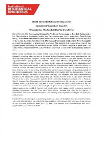
Figure 1 Wind load distribution in classes for Germany
Eurocodes Snow/Ice (Germany)
Figure 2: Snow load distribution in classes for Germany
Project IEE/08/593/SI2.529236
Summary report – R2.17 - Mechanical load resistance testing
Page 11 of 30
4.2. Boundary effects
conditions
and
resulting
forces/
Incident angle The angle of slope is influencing the load situation basically. This is true for wind and snow induced loads.
Figure 3: Different load situations resulting from wind and snow
Temperature The temperature of collector parts is correlated to their strength, adhesion strength, brittleness and stiffness. So it makes a difference if the resistance against mechanical forces is tested at elevated or at very low temperatures. The effects of this are very difficult to simulate because many of the used materials and components can not be described with parameters detailed enough. As well the combination of different forces and lots of components along the mounting are limiting the simulation.
Surrounding buildings and collector fields Indeed the wind speeds and snow loads are as well strongly influenced by the surrounding of the location where the collector(s) is/are installed. For example collectors can be mounted at a façade of a building and depending on its height they can be exposed to very high wind speeds. Project IEE/08/593/SI2.529236
Summary report – R2.17 - Mechanical load resistance testing
Page 12 of 30
Even rows of collectors in bigger installation affect the load within the field.
Dynamic forces When installing collectors in areas with lots of wind gusts, there is the possibility of generating dynamic loads at the collector. This is of course a totally different situation which is not at all represented by the current test.
Mounting situations
Figure 4: Illustration of different mounting situations
4.3.
CE-Marking and Classes
One has to take into account that CE will some how “ask” for at least a minimum of mechanical strength or better “structural safety” of the product taken under the regulation for building products. Two possibilities can be identified: 1. Define the lowest class to such a level that it is satisfying the requirements of CE-marking. 2. Define a minimum level in Annex ZA which has to be tested and passed to fulfil CE-marking requirements. From the industry point of view it would be desirable that a Solar Keymarked product would automatically fulfil the requirements of the CE marking. From this point of view only the first solution seems possible.
4.4.
Certification and Classes
As wind and snow/ice load is varying extremely around the world and it always an issue of local, national or regional requirements there has to be a very clear levelling up to which forces the collector was tested. The suggestion is not to correlate classes resulting from the outcome of the testing with the wind and snow load classes of existing standards. It would be to complicate to do this worldwide.
Project IEE/08/593/SI2.529236
Summary report – R2.17 - Mechanical load resistance testing
Page 13 of 30
One first very simple draft for classes could be: Table 1: Proposal how to document the results of the test (+ positive load, - negative load, < level of demage)
N/m²
1000
2400
5400
Classes
C
B
A