presented. This laminate uses shape-memory alloy (SMA) filaments which are ... made in the area of artificial muscles and biological tissues. M ost of these ...
Smart Mater. Struct. 5 (1996) 255-260 . Printed in the UK
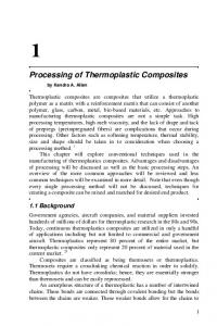
Super-active shape-memory alloy composites Ron Barrett and R Steven Gross Aerospace Engineering Department, Auburn University, Auburn , AL 36849-5338, USA Received 10 July 1995, accepted for publication 11 January 1996 Abstract. A new type of very-low-stiffness super-active composite material is presente d. This laminate uses shape-memory alloy (SMA) filaments which are embedded within a low-hardness silicone matrix. The purpos e is to develop an active composite in which the local strains within the SMA actuator material will be approximately 1%, while the laminate strains will be at least an order of magnitude larger. This type of laminate will be useful for biomimetic, biomedical, surgical and prosthetic applications in which the very high stiffness and actuation strength of conventional SMA filaments are too great fo r biological tissues . A modified form of moment and force-balance analysis is used to model the performance of the super-active shape-memory alloy composite (SASMAC). The analytical models are used to predict the performance of a SASMAC pull-pull actuator which uses 10 mil diameter Tinel alloy K actuators embedded in a 0.10" thick, 25 Durometer silicone matrix. The results of testing demonstrate that the laminate is capable of straining up to 10% with theory and experiment in good agreement. Fatigue testing was conducted on the actuator for 1 000 cycles. Because the local strains within the SMA were kept to less than 1%, the element showed no degradation in performance.
1. Introduction In the past five years, a great deal of progress has been made in the area of artificial muscles and biological tissues. M ost of these efforts have been concentrated in the area of polymer research and have yielded a host of new materials whi ch are capable of sizable actuation strains. The work of higa and Kurauchi (I] examined defonnations which may be generated in polyelectrolyte gels which are exposed to electrical fields. They showed that significant strain ra tes may be commanded through a variation in electrical potenLial across the gel. D oi and coworkers [2J continued the work i nto el ectrochemical artificial muscles as they examined the perfonnance of ionic polymer gels. Al though similar, their work demonstrated slightly better actuation characteristics. A t about the same time, the groups of Segalman [3J, Osada [4 J and Pei [5J demonstrated yet more viable configurations of artificial polymeric muscles. Following this early work, Shahinpoor and Mohsen (6] further investigated electro-actuated polymers. As was the case with most configurations of electrochemical artificial muscles, he showed response periods greater than five seconds. Because the response times of electrochemical artificial muscies are very low and often the chemicals used are not biologically compatible, several investigators have explored other methods of em ulating muscle ti ssues. One approach involves the use of shape-memory alloy (SMA) elements which provide extremely large forces at strains from 2 to 0964-1726/96/03025 5+06$19 .50
©
1996 lOP Publishing Ltd
3% cyclically with very little evidence of actuation fatigue. Among the uses are robotic manipulators, appendages and end effectors (7,8]. Because SMA elements are easily actuated and provide respon ses under 200 ms, they are fairly suitable as artificial muscles. However, several problems must be solved before they may be successfully used as in situ prosthetic devices or implants. One of the more significant difficulties is that the actuation strength of SMA is so high that biological tissues often y ield when they encounter such high forces. Other problems include locally high temperatures which can easily cauterize local tissues if the transfonnation temperatures are too high and the elements are poorly insulatecl. If animal m uscle tissue is to be emulated, then (I) the actuation strains need to be increased from 2 to 3% cyclically to 10 to 20%; (2) the thennal loads imposed on the body must be minimized globally and the temperature must be kept below 120 OF locally ; (3) all constituents must be biologically compatible; and (4) response times should be less than 500 ms. T his paper will present one new type of super-active material which meets most of these criteria and, accordingly, may be a new type of feasible artificial muscle tissue.
2. Actuator modeling 2.1. Laminate confi guration The super-active shape-memory alloy composite (S AS M AC) laminate is composed of two major constituents. 255
R Barrett and R S Gross fully contracted to trained position of SMA ;-------� -------~
14
lo'----------------~.I
~~=====~==IY=e.p=~=====t = ded'oC~=== fiO~===i O[Sit=c=eon===========rc===~=========3~ Figure 1. Schematic of hybrid bending-extension SASMAC actuator element.
Th e fi rst is a series of SMA filaments which are actuated in be nding . The second const ituent is aery-low-modulus silicone matrix. "Dle low-modulus matri x should be from 20 to 40 Durometer and shoul d be matched to (1) provide fiber stabili ty; (2) insulate the fibers electrically and ther mally; and (3) allow for rel atively unimpeded mo tions dur ing maxi mum defl ection. T here have been many different types of SASMAC actuators conceived. In general, there are fi ve main types that have been researched: ex tension act ive, shear-active, twist-active, hending-active and hybrid extension. Ge nerally, the extension-active el ements have SMA filamen ts that are trained only for extensi on and con traction along the axis of the filament. Because low-modulus, high-strain actuators are needed for artificial muscles, this high-actuation strength, low-strai n ac tuator wi ll not be considered. The second type of SASMAC actuator el ement is shear-active. Th is type of eleme nt generates in-plane shear forces which may be used to move components . Again, this type of actuator generally induces strains that are much too low to be useful as artificial muscles. The third type of element uses a pair of shear-active elements or a single twist-active element to induce twist deflections. Although several smaller muscle groups provide torsional control and stability, most biological structures do work through axial motions. T he fourth type of SASMAC actuator element uses a pair of extension-active or a single bending-active SMA element to induce bending deflections. Although these types of active composites may be highly useful for robotics applications, there are few muscle groups that are capable of acti vel y bending (the tongue is one significant exception). The last form of SASMAC composite uses bending motions to form a type of wavy surface which is capable of extending and contracting. This type of configuration is analogous to the way that active polymers or myosin contract and expand on a molecular level. Figure I shows a schematic of a hybrid extension SASM AC composite.
256
[f--o
(1J
o ~--~-----~-------------~-------~ o 4 10 12 14 18 16 StraiD, E (%)
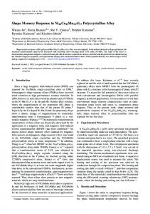
Figure 2. Stress-strain data on low-hardness silicone rubber.
There are two main ways that a hybrid bending extension SASMAC actuator eleme nt may be constructed and energized. The first method uses strai ght-trained SMA elements which are wound around a curvilinear mandre l and cast with a wa vy form. This type of SASMAC elemen t would act as a compression actuator when heated. The major difficulty with this type of active composite is its propensity to buckle even further out-of-plane when exposed to compressive loads. A better form of SASMAC actuator uses bending-trained SMA filaments which are cast into a flat sheet of silicone matrix. W hen actuated, the SASMAC would contract to a shape akin to that of the trained shape of the fila me nts. This scheme more closely emulates natural actuator fibers, is not susceptible to buck.ling, and is shown in figure I.
2.2. Constituent properties The two main constituents of the SASMAC composite are SMA filaments and a silicone matrix. Since the type of SASMAC under investigation is specifically intended as a cyclical actuator, the type of S MA was chosen for high resistance to actuation fatigue. From reference [9], Tinel alloy K was selected. Because many sets of muscles undergo millions of cycles in a year (skeletal muscles: 50000 to I OOOOOO/year, pulmonary: 2000000 to 20000oo0/year, cardiac: 10000000 to 50000000/year),
Super-active shape-memory alloys composites absolutely no actuation fatigue must be present in the system. Accordingly, one way of en suring that the SMA will experience no fatigue is to expose it to less than 1% strain. U nfortunately, this low strain level does not take full advantage of the capabilities of SMA, but the resistance to fatigue is paramount. This low strain level, however, does significantly simplify the analysis as the SMA remains primarily in the linear range. The modulus of T inel alloy K at 70 cF is approximately 1.45 Msi, and 8.70 M si at 320 of [9). Because the operational temperatures of the SMA will vary from approx imate Iy 100 to 300 of . a temperature insensitive, low hardness material was sought. Because silicone rubber met these criteria and was also biologically inert, it was chosen as a suitable matrix material. A special type of 25 Durometer silicone rubber with adhesive agents was tested. A test on a 2" long, 0.1" square coupon yielded the data shown in figure 2.
2.3. Moment and force matching models Using the geometry of fig ure I, it may be assumed that the moments generated by the silicone matrix are matched by the SM A moments at all points, including the apexes. Because the SM A modulus, ESM A, is a function of temperature, the moments generated by the SMA filaments will change. For the low-strain region of interest, it can be seen that the modulus of T inel alloy K can be approximated as: E ~ -0.508 + 0.028 8T , where E (M si) and T (OF), and 70 "[, < T < 320 "F. Assuming the stiffness of the silicone matrix may be characterized by a second-order relationship, and assuming the curvature remains constant from section to section, an expression equating these moments may be obtained. If the local strain s within the silicone are kept under 2 % , then a second-order expression for stress as a function of strain will hold, where E s l is the linear modulus, a nd E s2 characterizes the non-linear effects. ( I) Equation (1) is assumed to hold for one-way, tensile strain, with a mi rror of the expression valid for compress ion (for E < 2%). If it is assumed that the middle of the lam inate (where the SMA filaments are embedded) does only a small amount of work when bent, then an additional bending stiffness due to the presence of si licone (instead of a void from the SMA ), will contribute negligibly. Accordingly, a very simp le expression for the maximum moment generated by the laminate may be obtained by in tegrating throug h the thickness from the middle for each fdament segment:
(2) Because the silicone is cast flat, then actively bent by the curvilinear-trained SMA filaments , a si mple relationship may be obtained for the longitudinal strain as a function of depth within the laminate, where y is the through-thickness dimension and is measured from the mid-plane E
=
y/r c .
(3)
Using equations (2) and (3), an expression for the moment generated by the silicon e is obtained: (4)
A similar analysis of the SM A filaments is formulated assuming that the filaments have circular cross-sections and trained to a curvilinear state with a zero-stress radius of rcmin. Accordingly, the silicone moment of equation (4) is seen to be balanced by the SMA moment of equation (5):
(_1__ ~)
MSMA = ESMAr; 4
+
ES2t;b 32r;
r Cmln
=
rc
Msilicon e·
(5)
Although this rudimentary model neglects many highly non-linear effects which are present in the laminate , it offers a simple and effective method of solution for the local section curvature, re. Once the curvature is obtained . it may be cast in terms of the global laminate strain by equation (6). E
. (lo) = -2re slO lo
2re
(6)
- 1.
Using the geometry of figure I and the basic relationships above, the axial force of the laminate may also be determined and used in an equilibrium relationship. It can be seen that the moments which are balanced in equation (5) may act through a distance to the global laminate mid-plane, as given by equation (7):
D
= re(1
- cos(lo / 2re))
=
re(1 - cos(a / 2)).
(7)
This force estimation assumes that the external force, FexI , of figure I is acting upon the laminate and that it is distributed equally among all the fibers with no applied moment at the end. Equation (8) shows the approximate amount of axial force whic h is delivered by the SM A filaments. FSMA
+ Fmalrix =
ESMAr; 4(1 - cosUo/2re))
1 (E S\l;b - (1 - cos(l0 / 2rJ) ~
= F exlernal.
+
(I- - I) re,","
rc
ES2t;b)
32r;
(8)
The models of equations (5) and (8) are used to optimize free laminate performance . A moment matching plot may be obtained for a SASMAC laminate composed of the silicone described in figure 2 and 10 mil diameter Tinel aIJoy K. It can be seen in figure 3 that the total laminate strain varies from 0 (totally elongated) to more than 25% (compressed). Using the moment matching data, the geometric parameters which yield the greatest free- strains may be determined. Figure 4 shows that a spacing ratio of 1 yields an optimum solution at a thickness ratio of ls/(2ro) 29. (Further non-dimensionalization is difficult as the constituent behavior is non-linear). It can also be seen that a spacing ratio less than 1 would yield an even stronger optimum. This is physically possib le, but would require an offset spacing in the matrix. 257
R Barrett and R S Gross C
!== ~
.006
SMA moments 250°F 300°F
.s .004 r:I
200°F
.003
150°F
OJ .002
100°F
.e "
~
...~
b = 2ro= 0.01 in.
.005 si licone moments
:::>-":;~>--