Dorothy Carr. Porter. ¥. University of Kentucky ... The ARCHway project architecture for Image-Based Electronic. Editions. .... maintain efficiency of XML processing in main memory, segment ..... first constructing a document model (for example, using the document ...... manuscript gets a single entry in a folio node (lower right.
International Journal on Digital Libraries manuscript No. (will be inserted by the editor)
Support for XML Markup of Image-based Electronic Editions �
Alex Dekhtyar , Ionut E. Iacob , Jerzy W. Jaromczyk � Porter
��
�
�
, Kevin Kiernan , Neil Moore , Dorothy Carr
University of Kentucky Received: date / Revised version: date
Abstract. Image-based electronic editions enable researchers to view and study in an electronic environment historical manuscript images intricately linked to edition, transcript, glossary and apparatus files. Building image-based electronic editions poses a two-fold challenge. For humanities scholars, it is important to be able to use image and text to successfully encode the desired features of the manuscripts. Computer Scientists must find mechanisms for representing markup in its association both with the images, text and other auxiliary files and for making the representation available for efficient querying. This paper addresses the architecture of one such solution, that uses efficient data structures to store image-based encodings in main memory and on disk.
1 Introduction Image-Based Electronic Editions of historic documents and document collections are beginning to emerge as important new resources for humanities scholars and the general public. These editions can provide at the same time any number of researchers simultaneous first-hand access to digital images of unique and fragile material that is not otherwise widely available for study. The Image-Based Electronic Edition (IBEE) is different from most literary and historical humanities projects � ��� �����
Department of Computer Science Department of Computer Science Department of Computer Science
Department of English � Department of Computer Science Research in Computing for Humanities
undertaken to date. Traditionally, such projects either present textual notes without direct access to the physical object (or objects) on which the text is [1], or offer facsimiles of primary resource material without direct reference to the text [2]. Those projects that have presented both text and image have not used markup to associate the text with the manuscript page [4], or they provide markup that does not serve as a guide for the manuscript page [12]. Our concept of the Image-based Electronic Edition goes beyond simply viewing the image alongside text, and instead strives to integrate image, text, and markup. The problems studied in this paper arose in our work on the ARCHway Project, a collaboration of humanities scholars and computer scientists with the aim to solve the technological problems that arise from the highly complex encoding required by the seamless integration of images and text. ARCHway has worked to develop an Edition Production Technology (EPT) to facilitate the creation and maintenance of IBEEs. Our discussion of IBEEs in this paper is based on extensive practical experience building editions from Old English manuscripts, damaged by fire in the eighteenth century and now in the British Library [17,3]. Electronic Beowulf (eBeo) (first released in 1999, version 2.0 released in 2004)[23], is the prototype for one concept of the image-based electronic edition. eBeo provides full-color, high-resolution images of the entire Beowulf Manuscript (as well as its composite codex British Library Cotton Vitellius A. xv), including images taken under ultraviolet and fiber-optic light. In addition, eBeo includes a transcription and edition of the poetic text, a complete glossary, facilities for searching through the SGML-encoded source files, and links between text and image on the folio level. The original SGML (now XML)
2
Dekhtyar et al.: Support for XML Markup. . . Editor
End User
Editing Tools
Presentation Tools
Middlware
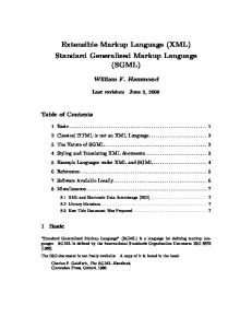
Data Mgmt. Fig. 1. The ARCHway project architecture for Image-Based Electronic Editions.
encoding is extensive and includes markup for textual divisions as well as the interaction between the text and the page: scribal corrections, damage that renders text difficult or impossible to read, paper frames that cover up page edges, and other physical aspects of the manuscript. An image-based electronic edition (IBEE), therefore, is not simply an electronic version of a facing-page facsimile with, for example, an edited text in one frame and a facsimile image in another. The creation of an IBEE, then, involves more than simply placing a documentary transcription (for example, an XML file translated with XSLT to represent the manuscript page) side-by-side with an image of the folio. In [24], we define the IBEE as a complete collection of all manuscript images intricately linked to edition, transcript, glossary, and apparatus files to allow users to view, read, compare, study, and search in an electronic environment that maintains and encourages analysis involving both the edited text and the actual images that establish that particular edition ... editorial interventions become completely transparent by the availability of high-resolution images alongside corresponding textual notes, explanatory notes, and bibliographical materials. eBeo is a good first step in the development of fully interactive editions with comprehensive links between image and text. However, in order to develop IBEEs further we must address open problems critical to their success.
Figure 1 depicts the ARCHway approach to IBEEs. The software architecture consists of three layers: application, middleware, and data management. The top layer divides into two parts: editorial tools for developing the IBEE and presentation tools for displaying the prepared electronic edition. Thus, we conceptually represent the as a “Y” shape, with the left “arm” forming the Edition Production Technology (EPT), and the right “arm” – the IBEE deployment software. At the intersection of the Y is the middleware, which integrates the different editorial and presentation tools and provides a level of abstraction between them and the data management layer. The latter layer contains the facilities for storage, maintenance and retrieval of the accumulated information. The Y also helps distinguish between the work of computer scientists and software developers in the leg of the “Y” and the work of the humanities scholars (editors), which includes the design of the editorial tools and the ultimate use of the IBEE. Both “arms” of the “Y” share the bottom layers of the software, while the applications residing on top of these layers are customized to perform specific editorial or presentation tasks. This organization of IBEEs poses a number of unique technical challenges. Among them, the problem of proper management of continually accumulating data lies at the heart of IBEE construction. As outlined above, the information managed by the IBEE software consists of three types of data: (a) images, (b) transcript and (c) edition: the integrated XML encoding of image and transcript. To create an IBEE, the editor studies the images and introduces appropriate XML markup in the transcript, transforming it in the process into an image-based edition. Because the vast majority of all markup has its origin in the images of the primary source, the manuscript, the resulting XML encoding must somehow incorporate the mapping between different regions of the image files and XML encoding of the text. Adding complexity to the problem of image-based markup support is the fact that the collection of XML tags used to encode document features forms multiple XML hierarchies [30,9,10,13] and the encoding itself contains conflicting markup that cannot be easily represented in a single XML document. Conflicting markup occurs, for example, when the editor encodes both the folio lines of the manuscript and the verse lines and the sentences of the edition. Many sentences begin and end in the middle of a manuscript line, a situation that produces malformed XML.[30]. Our solution is to encode multiple XML hierarchies concurrently, using special processing to output well-formed XML documents combining elements from one or more hierarchy. In this paper we begin to address the problem of support for image-based markup. We propose data structures
Dekhtyar et al.: Support for XML Markup. . .
and algorithms that allow us to store image-based encoding in relation to both text and images. In particular, we address the issues of storage and maintenance of such encoding in both main memory and in secondary storage. The solutions we propose include the use of segment trees [5,25] in main memory and of a modification of R-trees [16], called folio R-trees in this paper, in secondary storage. These solutions are complementary: segment trees reside in the ARCHway middle layer, while the folio-R trees are used in combination with a number of other index structures to preserve the information in non-volatile storage at the data management layer. To maintain efficiency of XML processing in main memory, segment trees preserve the complete mapping between images, text and concurrent (multihierarchical) markup; they are the first data structure to support such a mapping consistently throughout the lifecycle of an image-based electronic edition. At the same time, we design folio Rtrees with a view of minimal changes to the structure of an XML database management system, and, thus, encode only the mapping between the image and the text. To deliver information about related markup, we rely on the remainder of the database storage containing the XML encoding of the text. Because they are optimized for secondary storage, folio R-trees easily support documents too large to fit into memory. Segment trees for such documents, on the other hand, must be constructed and processed in chunks which fit in main memory—say, 20 folios at a time. We do not deal with such extensions to segment trees in this paper, as the text and markup of the documents which concern us rarely exceed a few megabytes in size. The rest of the paper is organized as follows. In Section 2 we describe in more detail the intricacies of imagebased electronic editions and the problems associated with the management of concurrent image-based markup. Section 3 discusses the notion of concurrent markup and how it affects the problem of management of image-based document-centric XML. Section 4 outlines the expectations from data structures employed to manage imagebased markup, and Sections 5 and 6, respectively, discuss the use of segment trees and folio R-trees for this purpose.
3
and a complete edition in a single work. Such a book— perhaps also including extensive notes, appendices, references, and indices—would be unwieldy, complex, difficult to use, and extremely expensive. The IBEE not only brings together many different types of files (image, text, glossary and other apparatus), but also integrates them with one another, forming a complete multimedia edition. Such integration offers substantial benefits for the edition’s end users—for example, an apparatus that is easily available and interactive. An IBEE might have an extensive search facility that can hunt for words or topics across multiple areas of text and image. Serving the same basic function as appendices in a print edition, the electronic search enables the user to take advantage of textual and image markup. The other main content of IBEEs, in addition to manuscript images, is text. As with traditional print editions, the editor must first make a transcription of the text. However, creating a transcript is not always as simple as copying letters, words, and sentences line-by-line from a manuscript page. Many manuscripts, such as those burned in the Cotton Library fire[26] have sustained damage that renders them partially or wholly illegible. UV and fiber-optic backlighting often enhance portions of damaged text, but there are instances where sections of the manuscript are so damaged that there is no apparent way to regain the lost writing. It is important for the editor in this case to be able to place encoding in the transcription that indicates exactly where the damaged areas are in the manuscript image, and how much the damage interferes with the textual readings. A user of the finished edition will want to know what text in the edition comes directly from the manuscript, what text has been slightly damaged, and what text has been damaged to the point of illegibility and thus either copied from another manuscript or conjecturally restored by the editor.
2 Issues in Building Image-Based Electronic Editions
For the integration of IBEEs to work, it is vital to create a mapping between folio images and the textual markup based on those images. We approach the imageto-text linking in two ways: 1) transcription markup must include information about the condition and appearance of the manuscript and 2) the edition must be able to use this information to connect specific areas of the folio with the textual transcription. While the focus of this paper is the management of the markup, it will be helpful to introduce some of the concepts that make our markup so complex.
The basis for all editions of medieval texts, whether print or electronic, are the manuscripts that preserve them. Although a print edition might include a few example facsimile images or a facsimile might include transcriptions, it is not common practice to include a complete facsimile
The dominating issue contributing to the complexity of IBEE markup is conflicting markup. Conflicting markup occurs when textual divisions (e.g., letter, word, poetic line), manuscript organization (e.g., folio, folio line), or manuscript features (e.g., damage, text visibility) overlap one another. As the editor encodes these fea-
4
Dekhtyar et al.: Support for XML Markup. . .
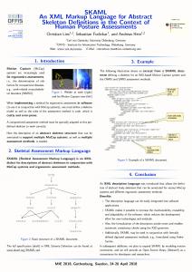
Fig. 2. hæfde
tures, the resulting XML becomes inevitably not wellformed. A simple example would be, as is common in Old English manuscripts, when a word like scyldingas below is divided across a manuscript line: ... glædescyl dingas ... Another example is when damage affects portions of one, or several words in a line: a se wisdom a
there is no guiding method to their placement, other than the appearance. In Figure 2 the box surrounding d also encloses portions of the bars of f. This is quite different from selecting a letter in a text file, where characters are atomic and it is impossible in a text file to select only part of a letter. Our technical approach recognizes that overlapping within the manuscript image is inevitable, and takes that into account when mapping between text and image. Text and image mapping is central to the creation and final deployment of the IBEE. In theory it is possible to map between text and image by simply placing the coordinates of a bounding box within attribute values as in the following example from Figure 1 above: hæfde
Although this approach stores coordinate values, it does not provide a mechanism for efficient lookup. The data structures presented later in this paper allow for faster access to information in the image-text mapping.
�
Both of these instances disobey the most basic rule of well-formed (single-hierarchy) XML: an element cannot end before another element that started after it. However, it is precisely this “ill-formed” markup that gives us the ability to fully describe the manuscript folio in the textual transcription. When features overlap in the manuscript, the elements describing them will overlap in the markup. For an image-based work to turly serve as a cultural road map for modern readers, the editor must encode image and text in such a way as to bring the manuscript to the forefront. The editor must connect all significant features in the transcript to the folio page on which it resides. An editor of an ancient text might want to describe individual letters. Although letters in a printed text never overlap, letters often occur in ligatures and other forms of overlapping in manuscripts. In Figure 2, the three center characters overlap one another in the word hæfde. The tongue of the æ, coming out of the high e-head, joins the f to form its stem. The ascender of the d then curves around over the f ; while it is not connected to the f, the ascender is in its vertical space. Textually, this is not a complicated example. We have one word, consisting of five letters, and two of these letters form a ligature. An editor using our tagger tool to describe the paleographical features of these letters would first draw bounding boxes around the individual characters. In doing so, he would inevitably include portions of the surrounding words in these boxes. The boxes overlap freely;
3 Concurrent XML Markup As we have seen, conflicting markup, presents one of the biggest challenges for development of a comprehensive solution for the problem of management of imagebased, document-centric, XML markup. This presents an outstanding challenge for a new framework, because traditional XML processing techniques are tailored towards data-centric XML data and are typically applied to individual, well-formed XML documents, assuming no markup conflicts. 3.1 Representing multiple hierarchies in textual form Although for efficient processing we store markup in internal or external data structures, it often becomes necessary to convert the markup into some kind of textual representation, such as XML [7]. Standard XML, because it describes a strictly hierarchical structure, is not sufficient for representing multi-hierarchical markup. The text encoding community has recognized this problem, and the latest guidelings of the Text Encoding Initiative (TEI P4) suggest several approaches to dealing with conflicting markup [30]. We can encode multiple hierarchies in a single XML document by using special notation such as fragmentation or milestone elements, as suggested by TEI; we can extend the syntax of XML to create what is really pseudo-XML, or we can store each hierarchy in a separate XML file.
Dekhtyar et al.: Support for XML Markup. . .
The milestone approach simulates multiple hierarchies with milestone elements, empty elements that mark the beginning and/or end of a region of text: Wisdom In the milestone approach to multihierarchical XML, some of the markup ranges are represented by milestone elements at the beginning and end of the marked-up region of text, rather than the normal opening and closing tags. In some cases, one hierarchy is encoded as normal XML, with milestones for the other hierarchies; an alternative approach is to use milestones for all the markup. Fragmentation is another way to incorporate multiple hierarchies into a single XML file. In this approach, whenever the scopes of two elements overlap, one of the elements is fragmented, broken into two (or more) subparts, each with its own start and end tags: Wisd om The fragments are combined using special link attributes. Link attributes can, as in the example above, simply provide unique identification for all fragments, or be used to create a double-linked list of all fragments. Yet another approach extends the syntax of XML to allow overlapping elements [13]. This recourse is pseudoXML. Consider, for example, the following fragment:
5
Pseudo-XML, as well as the straightforward milestone approach, assumes that an element cannot overlap with another element of the same name. If such an overlap occurred, the closing tag associated with the first element could be misinterpreted as belonging to the second. We can eliminate this ambiguity by assigning to each start tag a unique ID, and by listing this ID in both the start tag and corresponding end tag (perhaps as an attribute). See [11] for one possible approach to using start IDs and end IDs to connect milestone elements. However, if the document is required to conform to a set of DTDs, this kind of overlap can be disallowed, as the two elements are defined in the same DTD and are thus required to be well-formed with respect to one another. The database community has recently recognized the importance and complexity of the issues of management of markup from concurrent hierarchies. In [20] Jagadish et al. describe colorful XML – a mechanism to incorporate markup from multiple hierarchies in a single structure for data-centric XML encodings. Their work reflects understainding of the same problems encountered by the humanities scholars: there are times and situations when the XML markup of the underlying data becomes too complex for a single hierarchy to store it correctly and efficiently, and for such situations, new data structures, processing algorithms and software have to be developed.
Wisdom Here, the content Wisdom contains two overlapping tags, and (this example is further presented in Figure 5). Pseudo-XML has the disadvantage that it cannot be parsed with standard XML parsers. However, if we can deduce from the name of an element the hierarchies to which it belongs, we can use simple text-processing tools to extract the markup belonging to a single hierarchy. This insight underlies the “Just-In-Time-Trees” technique described in [13]. In section 5.6, we show that pseudoXML can easily be parsed into a range-based representation. Another way to approach concurrent hierarchies is to store them concurrently, i.e., maintain a single XML file for each markup hierarchy used in the encoding. This approach allows for the use of XML parsers to parse individual hierarchies, but management of the overall markup has to be facilitated by additional software. In [9,10] we have described the maintenance apporach to concurrent XML based on this idea. There, we have developed efficient algorithms for converting between XML documents stored in such distributed way and XML documents that employ fragmentation to store markup from all hierarchies in the same file. And in [19] we described the parser for the proposed distributed XML documents.
4 Data Structures to Support IBEEs: Overview From the data management perspective the uniqueness of Image-based Electronic editions lies in the way images guide the creation of the markup. In this section we describe the issues we must resolve. Preservation of the text-to-image and XML-to-image mappings is facilitated by a number of the editorial tools that reside in the application layer of the EPT (see Figure 1). Among these tools are a document-centric XML editor and image management tools. To be able to keep track of the mapping, the image management tool provides the editor with the functionality to highlight a region on the image. This information is then shared with the XML editor for the explicit purpose of associating the image coordinates with the tagging task underway. Thus, our goal is to provide efficient data management support for the following tasks: – storage of document-centric XML based on an existing (and potentially large) text file; – insertion of image-based XML encoding; – preservation of the image-to-XML and image-to-text mapping established in the editorial tools;
6
Dekhtyar et al.: Support for XML Markup. . .
– efficient retrieval of information related to the text/XML- 5 Using Segment Trees for the XML Markup to-image mapping. Process To address these issues, we consider two possible scenarios. In the first scenario, all data storage and data management occurs in main memory, while in the second, all information resides in secondary storage. Both scenarios are viable and, in fact, complementary. Mainmemory processing is bound to be more efficient, but has certain limitations on the size of the objects. At the same time, even when the XML constructed for an electronic edition is large enough that it precludes storing all the data in main memory at the same time, in-memory processing can be used on buffered fragments. Secondary storage processing ensures the scalability of the proposed approach and alleviates the problem of information volatility. Our approaches to storing data in main memory and on disk differ somewhat. For main-memory processing (Section 5), we choose to use the well-known in computational geometry segment tree [25,5] data structure, which will, in essence, replace the traditional DOM tree in storing XML, with the additional benefit of linking XML and text to the document images. The segment tree insert and delete algorithms proposed in the next section demonstrate how this structure can be efficiently maintained. We describe the stab algorithm to illustrate how the proposed way of preserving the mapping efficiently answers range queries: queries that find text/XML inside a given region on an image, and find the region(s) on images that contain specific text/markup. In contrast to the all-in-one approach of segment trees to managing image-based XML, our secondary storage data structures (Section 6) separate the storage of XML from the index structure designed specifically to preserve the text-to-image mapping. At present time, representation of XML in relational databases is an area or active research[32,28,15,6]. In this paper, we factor out the problem of representing XML in a relational database, by taking the “black box” approach: we assume that XML is stored in a manner that allows us to process efficiently the following queries: – Given a range in the text content (PCDATA), find all XML elements whose content is a subset, superset or overlaps the range; – Given an XML element node, find its full content. Adopting this assumption allows us to shift our attention to the problem of preserving the text/XML-toimage mapping in the secondary storage database. We address the latter problem by introducing a data structure called folio R-tree, an R-tree derivative, tailored for the specifics of the manuscript images. The details of both approaches are shown in the next two sections.
A collection of data structures supporting successful markup for the class of manuscripts that we are considering must satisfy several requirements: – it must be able to represent multi hierarchical XML that corresponds to a set of document type definitions selected for the given edition. – it must lend itself to effective representation of the geometry of manuscripts and its intuitive implementation in the user interface – it must be dynamic to allow for additions, deletions and modifications of the markup – it must be efficient to provide quick response time – it must support search queries – it must support efficient conversion to XML, to allow the use of standard XML processing utilities The image-based approach to the tagging process suggests that it is advantageous to use geometric structures [27,21,22]. The choice of structures depends on the particular needs of the editorial process. Specifically, there are manuscript features such as the shape and spatial distortion of the page that are best viewed in 3-dimensions. Damage and restoration, as well as marginalia, are best viewed as 2-dimensional features. Finally, we can view the text and its linear structure in 1-dimensional space. In this section we focus on this linear view of the text and discuss how to incorporate 2-dimensional features. In the rest of this section we describe and demonstrate how we adopt and adapt the segment tree [5] structure to this end. 5.1 The tagging process In order to lay the groundwork for formal presentation, we need to make a number of assumptions about the structure of the document and the process of adding imagebased markup to the electronic edition (called “tagging”). We consider markup that applies primarily to the text of the manuscript. For our purposes it is presented as lines of letters. Each line is marked by a curve below the line, called a line trace. Because lines of text are often not exactly horizontal (whether because of damage, page layout, or scribal inconsistency), these traces need not be straight or parallel. Although our coordinate system is based on lines of text, not all document structure easily conforms to the layout of the text. These aspects of the manuscript require two-dimensional information for precise representation. It is possible, however, to partially encode these
Dekhtyar et al.: Support for XML Markup. . .
Fig. 3. Fragment of a folio image with line traces
features within our textual coordinate system. For example, text not included in the main body of the manuscript, such as marginal notes, can be represented by markup located at an appropriate point in the text, or at the beginning or end of the page if no appropriate location exists. The content of the note could then be encoded as an attribute of that markup. Damage to multiple lines of text can be represented with a number of markup elements, one per affected fragment of line. Large capital letters can be dealt with by adjusting the line traces so that the letter is contained in only one line of text. Finally, paleographical information, including complete two-dimensional coordinates if necessary, can be stored in attributes of the character representing the letter. The tracer automatically divides each line into a number of elementary segments. The number of segments depends on the manuscript. For example, if we wish our coordinate system to remain independent of the resolutions and scales of individual images, we may choose to have elementary segments 1/72 of an inch in width. In other cases it may be more natural to make each elementary segment a certain number of pixels wide. At other times, it may simplify matters to have each line, regardless of its width, contain the same number of elementary segments. With elementary segments established, the tracer identifies the endpoint of each line with the beginning point of the next. This establishes a one-dimensional coordinate system on the manuscript page; if �� is the number of elementary segments making up line � , the first line of the page extends from position 0 to position �� , the second from �� to ���� � , and so forth. If we furthermore identify the endpoint of the last line of each page with the beginning point of the first line of the next page, we have a single one-dimensional coordinate system capable of representing textual positions through the entire document. Because lines are connected according to the normal flow of text, we are able use a single interval to represent a textual feature which wraps across multiple lines or even pages. We assume that the markup to be applied conforms to a set of document type definitions (DTDs) [7] or XML
7
schemas [14]. In general, the sets of elements described by each DTD or schema will be disjoint except for the document root element and #PCDATA content, which are present in each. Elements of a document which are specified in the same DTD or schema must represent a well-formed XML hierarchy. Furthermore, for interoperability with XML, we require that letters be atomic: markup elements must contain whole letters and never a part of a letter. Similarly, letters within the same line must be separable: they must not overlap horizontally with one another. Although sub-letter markup (such as describing a part of a letter) and ligatures (where letters overlap) appear to violate these conditions, we can represent them using attributes. Finally, if two markup elements cover precisely the same interval, we leave the order of nesting undefined. If an element must be contained within another, and not the other way around, the inner element should cover a smaller interval. These conditions allow us to unambiguously represent the document as a collection of XML documents, each with the same content, or as a single multihierarchical XML-like document. We discuss in section 5.5 methods for producing such XML representations. Given these constraints on the structure of the document, we can choose our data structures for the representation of markup and content. If we have established a one-dimensional order on the manuscript, as described above, each letter and each markup element is represented as an interval in that coordinate system, possibly spanning lines or even folios. One data structure that efficiently represents a dynamic collection of intervals is the segment tree [5], which we describe in section 5.3. We can use the segment tree to perform some types of queries directly; other queries can be performed by first constructing a document model (for example, using the document object model [8]) containing the relevant markup [13], and using standard document-processing tools. In addition, the ability to define the size of elementary segments based on the manuscript images makes the segment tree structure more flexible and better suited for the image-based markup process than structures whose region boundaries are determined by the markup data. In our approach, the tagging process takes place in a number of steps. First, images are combined to form manuscript pages; for example, one page may consist of the blended overlay of a daylight image and an ultravioletenhanced image of the same leaf. These pages are arranged in textual order, and each page has its lines marked with traces. Once these steps have been performed, the editor uses a tagger tool to select ranges of the image and describe them as content (letters) or as markup elements, assigning attributes as appropriate.
8
Dekhtyar et al.: Support for XML Markup. . .
5.2 Representing multiple hierarchies in textual form
Wisdom [0,63]
Once a manuscript has been tagged and the segment tree built, it often becomes necessary to convert the markup to some kind of textual representation, such as XML [14], to facilitate document interchange. Normal XML, because it describes a strictly hierarchical structure, is not sufficient for representing multi-hierarchical markup. We can encode the hierarchies using special XML notation such as milestone elements; or we can extend the syntax of XML to create what we call pseudo-XML. Milestone elements, described in [29], are empty elements marking the beginning and/or end of a region of text. In the milestone-based approach to multihierarchical XML, much of the markup is indicated by milestone elements at the beginning and end of the marked-up region of text. In some cases, one hierarchy is encoded as normal XML, with milestones for the other hierarchies; in others, milestones are used for all the markup. Another approach, described in [13], is to extend the syntax of XML to allow overlapping elements. We call this representation pseudo-XML. An example of pseudoXML along with its XML segment tree representation is presented later, in Figure 5. Pseudo-XML has the disadvantage that it cannot be parsed with standard XML parsers. However, if we can deduce from the name of an element the hierarchies to which it belongs, we can use text-processing tools to extract a single hierarchy. This insight underlies the “JustIn-Time-Trees” technique described in [13]. In section 5.6, we show that pseudo-XML can easily be parsed into a range-based representation. Pseudo-XML, as well as the straightforward milestone approach, assumes that an element cannot overlap with another element of the same name. If such an overlap occurred, the closing tag associated with the first element could be misinterpreted as belonging to the second. We can eliminate this ambiguity by assigning to each start tag a unique ID, and by listing this ID in both the start tag and corresponding end tag (perhaps as an attribute). However, if the document is required to conform to a set of DTDs, this kind of overlap can be disallowed, as the two elements are defined in the same DTD and are thus required to be well-formed with respect to one another. 5.3 Segment trees for XML Markup Our XML-segment tree data structure is based on segment trees. The segment tree was introduced in [5], [25] as a geometric dynamic data structure to represent and to perform a number of update (e.g., insert and delete) and query operations on a set of segments. It is assumed
[0,31]
[32,63]
[0,15]
[16,31]
[32,47]
[48,63]
dmg
[8,15]
[16,23]
"W"
"W"
[24,31]
[32,39]
[40,47]
[48,55]
[56,63]
"m" [24,27] [28,31] [32,35] [36,39] [40,43] [44,47] "i" "s" "d" "o" [30,31] dmg, "s"
[42,43] "o"
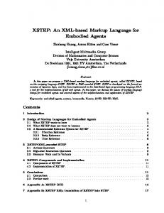
Fig. 4. Segment tree
that the coordinates of all the endpoints for the potential segments, but not the segments themselves, are known in advance. This corresponds in our case to marking entities along a given line, where each point on the line has its coordinate measured in some unit (pixels, points, millimeters, etc.), and selecting in the marking process ranges that bracket those entities. The underlying structure for the segment tree is a balanced binary tree with leaves representing atomic (or smallest, indivisible) segments. Each node represents the union of the atomic segments rooted in this nodes. For example, the root of the tree represents all the atomic segments. Intervals that belong to the collection represented in the segment tree are associated with nodes of the tree and satisfy the following property: a node stores if the union of its atomic segments is contained in but the union of the atomic segments associated with the parent of do not. Thanks to this property each segment is associated with at most � nodes because it needs to be represented at most twice on any level in the tree. In our adaptation, each node of the segment tree contains:
�
�
������� �
� �
��
�� ��
max indicating the lower and upper – A pair min bounds of the interval covered by . – A list elements of those elements and characters stored in (as described above). We need to traverse the list in sorted order; because of this, elements may be better represented as some form of binary search tree. – Pointers left and right to the left and right subtrees, respectively, of . If a subtree has not yet been constructed, or if represents an elementary segment, one or both of these pointers may be empty (which we represent by the symbol ).
��
��
��
�
For our application, each atomic segment’s endpoints correspond to two consecutive coordinates in the selected
Dekhtyar et al.: Support for XML Markup. . .
positioning system for horizontal lines in an image (in some cases we will use points as the atomic segments, as well). Segments correspond to the tagged ranges and they are named with the marking� tags. A sample seg���� ��� ment tree with atomic segments �� is depicted in Figure 4. To save space, only nodes that are marked or whose descendants are associated with marked ranges, exist in the tree. New nodes are added to the tree through insert operation if needed. One such node, which corresponds to a potential union of atomic segments but is not actually present in the tree, is depicted with dashed lines in Figure 4. This figure describes a set of intervals corresponding to the XML fragment
Wisdom [0,63]
� � ������� � �
[0,31]
�
�
�
“Wisdom”. Note that elements located in the same node of the segment tree are listed with the longer interval first. As discussed earlier, this is needed for the correctness of the traversal procedures to generate pseudo-XML documents from the segment tree. 5.4 Operations on segment trees
� � � �
Here we present two algorithms for manipulating seg�
ment trees. insert �� stores a new markup element in a segment tree; stab returns � a list of all the stored intervals which contain the point . In the following pseudocode, � refers to the root of the segment tree. Given a segment tree node � , we write � interval for the interval � � ����� �� ������� , and � �"!$# �&%(' � for the midpoint of
that � interval. Similarly, we write interval for the inter
val ����� �)����� of a markup element . The insert operation (Figure 6) first tests whether the
interval of the element will fit into the segment tree
�
�
� �
� �
� �� � �
[32,63]
[0,15]
[16,31]
[32,47]
[48,63]
dmg
[8,15]
[16,23]
[24,31]
[32,39]
"W"
"W"
rpr
rpr
[40,47]
[48,55] "m"
[24,27] [28,31] [32,35] [36,39] [40,43] [44,47] "i" "s" "d" "o" [30,31] dmg, "s"
“Wisdom”. Each letter and each markup element is represented by a segment, which typically spans a number of atomic segments. From the tree we can readily find the span of each range. For example, the tag covers a range from �� to � . Insertion of a new interval into a segment tree is a simple operation of marking some nodes along the insertion path in the tree. Basically, we want to mark the smallest number of nodes whose union of the corresponding atomic segments equals . This is done by placing the beginning and ending points of among the nodes of the segment tree in a fashion similar to the binary search, and marking the topmost nodes that lie between them. In Figure 5, we show the segment tree after inserting a range � for which spans the interval from to � ; the affected nodes are highlighted. This could be represented in pseudo-XML as
9
[40,41] rpr
[42,43] "o"
Fig. 5. Modified segment tree
1 2 3 4
insert * Element +-, if +/. interval 021-. interval insert-node *31�45+-, else report an error
5 6 7 8 9 10 11 12 13 14 15 16
insert-node * Node 6�4 Element +�, if 6�. interval 02+7. interval 6�. elements 896�. elements :@?"A@B2CEDGF�H�IJD�K/LM*N6�, if 6�. left OQP 6�. left 8 new Node *N6�. >R?SAT4UCEDGF�H�I�D�KVL�*N6�,U, insert-node *N6�. left 45+-, if +/. >RW�XRYZCEDGF�H�I�DGK/LM*N6(, if 6�. right OQP 6�. right 8 new Node *3CEDGF�H�IJD�K/LM*N6�,$[]\J4^6�. >RW�X�, insert-node *N6�. right 4U+�, Fig. 6. Inserting a markup element into a segment tree
(line 2). If it does not, we report an error (line 4), although we will see later how to expand the tree so that
it can store . If does fit, insert calls the recursive procedure insert-node on the root of the segment tree (line 3). The insert-node procedure takes as arguments a node
to be stored in the tree. If � ’s inter� and the element
val is contained in ’s interval, is to be stored in � , and is thus inserted into the elements list of � (line 7). In
this case, no descendant of � will store , so insert-node does not recurse into either subtree of � .
If, on the other hand, ’s interval does not contain � ’s interval, the procedure recurses into zero or more of
� ’s children. If ’s interval contains part of the left half
of � ’s interval (line 9), is recursively inserted into � ’s left subtree (line 12). Furthermore, if ’s interval con tains part of the right half of � ’s interval (line 13), is recursively inserted into the right subtree (line 16). If we
10
Dekhtyar et al.: Support for XML Markup. . .
stab * Integer $, if 1�. interval return stab-node *31�4 else return P
��
�
$,
stab-node * Node 6�4 Integer $, 6�. left OQP if BZCEDGF�H�I�D�KVL�*N6�, return 1�. elements : stab-node *N6�. left , else if YZCED&F�H�IJD�K/LM*N6�, 6�. right OQP return 1�. elements : stab-node *N6�. right , else return 1�. elements
��
�
��
�
Fig. 7. Stabbing query
need to recurse into an uninstantiated node (lines 10 and 14), we first instantiate those nodes (lines 11 and 15). The operation delete is implemented analogously to insert, and is not presented in detail here. Insertions and deletions are very efficient; they can be performed in time proportional to where is the total number �V� of atomic segments. For a manuscript with pages, �� each of which consists of lines of inches each, us� ing �elementary segments per��� inch, is bounded ��� �� � by .
The pseudocode in Figure 7 implements stab, a basic query operation which returns a collection of all the � stored intervals which contain the point� . The recursive search is guided by the position of relative to the midpoint of the current node. This query has logarithmic cost, plus the size of the output.
��� ��
� � � � �
�
��
� � �
5.5 Converting a segment tree into XML For interoperability with existing tools and data sources, it is important to be able to generate XML from a segment tree encoding a multihierarchical document. Depending on the nature of the data to be extracted, there are a number of possible translations. We may need to convert a segment tree into pseudo-XML or XML with milestones, or to extract a single hierarchy into wellformed XML. We may also extract a single hierarchy into a document object model ([8]) for further processing, skipping the textual XML representation altogether. The traverse() procedure (Figure 8) can produce either pseudo-XML or XML with milestones. To generate pseudo-XML, the output-start-tag() and output-endtag() procedures should output XML-style start and end tags. To produce XML with milestones, these procedures should generate empty “milestone” elements. In some cases we wish to extract a single document hierarchy. In this case, we are given a list of element names or a DTD and we output an XML document containing all the markup elements with any of the given
traverse( ) . elements for each + if +7. >@?SA O . >@?SA if + is a character output-char( + ) else output-start-tag(+ ) if left * , OQP traverse( . left) if right * , O�P traverse( . right) for each + �* . elements , if ( + is an element) and +7. >RW(X O output-end-tag( + )
��� �
�� ��
�� �
���������������� �
�
. >RW�X
Fig. 8. Segment tree traversal
names, as well as all the document content. If the named elements form a single hierarchy, this procedure should produce well-formed XML. We can use this procedure to partially validate a multihierarchical document with respect to a DTD: first, extract all the elements specified in the DTD, and run a validating XML parser on the result and the given DTD. To extract a partial document structure such as this, we modify the output-start-tag() and output-end-tag() procedures to output only the desired tags. In some cases, we may be unsure whether a collection of element names forms a hierarchy. We can use the partial traversal procedure described above to test for hierarchy, producing a well-formed XML document if possible. Each time we output a start tag, we push the element in question onto a stack. Before generating an end tag, we pop the top element from the stack and compare it to the element whose end tag we are to generate. If the elements are identical, we proceed; otherwise, the two elements overlap and so cannot form a hierarchy. In the latter case, we signal an error; if appropriate, we can attempt to recover from the error, perhaps by removing one of the overlapping tags from the output.
5.6 Parsing concurrent hierarchies In some cases, it may be necessary to translate existing XML or pseudo-XML markup into a segment tree. If the markup is already annotated with manuscript coordinates, this is a straightforward process: insert each element of the XML into the segment tree with the interval specified by the annotation. In many cases, however, we lack manuscript coordinates and wish to build a seg-
Dekhtyar et al.: Support for XML Markup. . .
��
�
parse-pseudo-xml() 8 new LinkedList Tag 4 Integer new SegmentTree 8
�� � � � ��� � � � � � �
��� � � �� � ��� ������ � �� � �� �
the segment tree, we grow the segment tree to double its previous size. End-tags are somewhat more complicated to deal with. When we reach an end-tag token with name , we scan � through for the most recently inserted tuple � where � . If contains no such tuples, the end-tag does not have a corresponding start-tag, and we report an error. Otherwise, we remove the tuple we located from �� (� an. We insert into the segment tree the segment notated with and , then increment . As before, we grow the segment tree if the new value of is greater than the rightmost point in the segment tree. If is nonempty at the end of the document, there were start-tags without corresponding end-tags. In this case, we report an error. Otherwise, we have a complete document, though it may not possess a root element (i.e., one which is an ancestor of all other elements and content). If necessary, we can insert a synthetic root element which covers the segment tree’s entire range. We can make use of the same procedure to parse milestone-encoded XML. The only difference is in the get-next-token() procedure; it should treat an opening milestone as a start tag, and a closing milestone as an end tag.
�
� &%'$
8
while O get-next-token() if is a start tag .
�A
*
4
,
else if is an end tag for * 74 M, O . A�W�> if 7. A�W�> . �>
+
�* J4 �,
8
new Element * . insert *N+-, 8
�
J. A�W�>
� �������� �� � ���
�4 J. W
74
-4
�
,
�
� �� � ���
� � �� � 8
[]\
�
. >RW�X if Y grow-segment-tree * , (If is not empty, report an error.)
$
�
$
�
[]\
break (If no matching elements were found, report an error.) else if is a character new CharElement * 4 4 , 8 . insert * ,
��
11
�
�
� �� � � ���
Fig. 9. Parsing pseudo-XML
ment tree which reflects the hierarchical structure of the XML document. To simplify discussion we ignore here XML features such as entity references, comments, CDATA sections, and processing instructions; these features do not tend to interact with multiple hierarchies, and may be regarded as special cases of character data or empty elements. We tokenize the XML or pseudo-XML input into start-tags, end-tags, empty-element tags, and characters. These constructs are defined in [7], and may be recognized by regular expressions. For simplicity, we translate each emptyelement tag token into the corresponding start-tag and end-tag tokens. We maintain a counter , which indicates the number of characters and elements encountered so far. We also maintain a linked list , each element of which is � a tuple � ; � is the� name of an element, is the element’s attributes, and is the position of the element (i.e., the value of at the element’s start-tag). We begin with an empty segment tree covering an empty interval; the procedure will grow the tree as appropriate. When we encounter a start-tag, we push onto the beginning of the tuple � , where � and are the name and attributes, respectively, of the tag. When we encounter a character , we insert into the segment tree � the segment (� annotated with , then increment . If the new value of is greater than the rightmost point of
�
� �! � �
"
�
� ���
�
�
#
� �� �!� �
#
�
6 Using Folio R-trees For Indexing Image Content When large manuscripts are encoded using a wide array of markup elements, the size of the encoding description becomes sufficiently large to justify the use of database management techniques as the back-end for Electronic Editions. As such, we must worry about the appropriate storage of a large amount of information: XML markup, glossary indexes, manuscript text, and text-to-image and image-to-XML mappings. Storage of XML in relational and other “native XML” databases has been subject significant research in the past 5–7 years [32,28,15,6]. We note here that the XML storage problem in the context of IBEEs is more complex than what had been studied in most of the work cited above. It is so for two reasons: (a) our XML is documentcentric, while most of the research to date concentrated on storing data-centric XML in databases, and (b) we need to store and efficiently access concurrent XML. We are currently investigating the problem of storage and retrieval of concurrent XML from XML databases, preliminary information can be found in [18]. In this section, we present our approach to indexing the text-to-image mapping in a database system supporting IBEEs. Our concentration is on the following four tasks:
12
Dekhtyar et al.: Support for XML Markup. . .
– Storage: given a flow of information about a manuscript folio image, create all necessary data structures in the underlying database. – Addition: given a collection of data structures in the database and a new encoding, extend the structures to store the new information. – Text Range Query: given a manuscript folio image and a rectangular box, find all the manuscript text and encodings found inside the box. – Image Range Query: Given some manuscript’s folio XML markup, find the corresponding folio image region(s). Out of the three tasks above, the first two serve to create and maintain the necessary data structures, while the third task retrieves information from the database. In the most general case, XML markup of the manuscript folio images can describe properties of arbitrary regions and stand outside the one-dimensional flow of the manuscript text. However, if, just as we did in the case of segment trees, we make some restricting assumptions about the nature of the XML markup used in the editing1, we can simplify the problem of storage of data significantly. In particular, the representation method described in this section assumes the following:
1. XML markup-to-text mapping: given XML markup, find its content; 2. Text-to-image mapping: given text content, determine the folio image regions in which it is located. We note that (a) Image-to-text mapping and Textto-image mapping and (b) XML Retrieval and XML markup-to-text mapping are complements to each other. In addition to that, the latter pair of operations, relating markup and text is independent of the text-image relationship. The solution to this problem depends primarily on the method of storage of XML markup in the database that is employed. In this paper, we assume that no matter what method is chosen, a reasonably efficient mechanism for answering these two queries exists. We further concentrate on dealing with image-text relationship.
6.1 Folio R-Trees
R-trees [16] have proved to be efficient and flexible in storing information about objects in multidimensional spaces. The defining feature of an R-tree is that the regions described by two sibling nodes in the tree overlap. While this makes retrieval operations, such as range queries, follow multiple paths through the tree, this is – The smallest (non-empty) unit of XML markup is a well compensated by the flexibility R-trees afford in storsingle character of the manuscript text (and appropriing objects. ate 2D bounding box on the image). Informally, a folio R-tree, a data structure for text-to– Any feature on the image is encoded in relation to image and image-to-text mapping, consists of three laythe transcribed text. ers of nodes. Nodes at the top layer, called folio nodes, – Empty XML markup elements have uniquely identiindex individual folios. Since each folio is represented fiable positions between the characters of the manuscript by a separate image, then each folio record stored on text. these nodes corresponds to a two-dimensional space of its own. Nodes at the second layer, line nodes, index lines Under these assumptions, we note the following: found on a specific folio. Finally, the third layer of nodes, character nodes, indexes characters of a single line. The Proposition 1. manuscript folios are sorted in ascending order, and each Under the assumptions above, the Text Range Query folio is associated to a single entry in one folio node. This problem can be solved by solving, in sequence the folentry contains a pointer to the page that indexes the lines lowing two subproblems: of the folio (the page of line nodes). Each entry in a line node stores information about a single line of a folio. The 1. Image-to-text mapping: Find all text in the given entry contains the id of the line (folio number, line numbox; ber), the rectangular bounding box for the line and the 2. XML Retrieval: Find all XML markup associated pointer to the character node which stores information with this text. about the characters from the line. Each character node entry contains the id of the character: (folio number, line Proposition 2. number, position in line), character itself and its bounding box. The bounding box of the line is maintained as Under the assumptions above, the Image Range Query the smallest rectangle that encloses all bounding boxes problem can be solved by solving, in sequence the folfor (currently known) characters in the line. lowing two subproblems: More formally, we define the data structures for the 1 These assumptions hold true for the Electronic Editions we are folio R-trees as follows: currently working on.
Dekhtyar et al.: Support for XML Markup. . .
line#
ptr
13
bounding box
1 ...
...
13 14 15 16 17 ...
...
21
bounding box
Lines
Characters Ptr
FolioID
..
..
... ...
1
2
3
... ...
4 5
6
... ... .. .. .. .. .. ...
value
7 8 9 10 11 12 13 14
CharID
1r 1v ... 38v ...
Folios
Fig. 10. Folio R-trees for manuscript pages.
consisting of folio, line and character records are called folio, line, or character pages or nodes respectively. The folio R-tree, then, can be defined as follows.
Definition 1. A folio record is a record of the form:
�
�������� �� �
$
�!� � �
��� �
�
��
��� � � �
�
��
#
�
�
�����
Definition 2.
������� �� ��
$
where
stores the name of a specific manuscript
��� � is the name of the image� file associfolio, �
� ated with the folio and � �� � and � �� ��� are a disk page address and a record slot id on the disk page respectively. A disk page consisting of folio records is called a folio page or folio node. A line record is a record of the form:
�
�
�
$
� ��
�
��
�
� ��
�$
�
�
��
��
�
�
� �� � �
�
�!�
�
�
��"
"
#
�
�! (�
�! (�
�
�
# �
�����
� �
where � �� �� � is the number (id) of the line on its folio, � "� , � # , � � , and � are the coordinates (upper left and lower right corners) of the bounding
box of the line on the folio image, and �! (� � and �
� �! �� ��� are a disk page address and a record slot id on the disk page respectively. A disk page consisting of line records is called a line page or line node.
�� � A character record is a tuple �! �� �,� �! (�%$ � , � � � �� , � # , � , &� , where �! (� is the iden� tifier for the character, �! (�%$ � is the character value itself2 , and � "� , � � , � � , and � are the coordinates (upper left and lower right corners) of the bounding box of the character on the folio image. Disk pages
"
�
�
� �
�
"
#
�
2
� � �
�
" � �
"
"
"
�
We assume that the character value is represented in Unicode.
%
� ����� � �
� Let � be a collection of manuscript fo�� lios and� ) be the text contained on these folios. By ) � , � � we denote the substring of ) contained '%* on folio . A folio R-tree + representing the manuscript ,� �)"� is a collection of folio, line and character nodes, such that �
� �
('
'
�
'�*�-
1. There exists a folio record for each folio� */. ; there exists a line record for each line of each ' * folio and there exists a character record for each character %0 of ) . � 2. The bounding box of any line is exactly the minimal bounding box for all characters from this line. 3. All folio records are sorted in the order prescribed by � ; all line records for a specific folio occupy consecutive records on consecutive line pages; all character records for a specific line occupy consecutive records on consecutive character pages. � �
� ��� 4. In each folio record, � �� and � �� point to the first line record for the given folio; in
� ��� point each line record �! �� � and �! (� � to the first character record for the given line.
�
"
�
�
"
�
#
�
#
A folio R-tree satisfying conditions 2,3 and 4 above, but not condition 1,� is called an incomplete folio R-tree for the manuscript �)"� .
�
14
Dekhtyar et al.: Support for XML Markup. . .
�
��
F-Tree-Update( , ����� , ���
Example 1.
�
input:
Consider a fragment of a folio R-tree depicted in Figure 10. It shows how the folio R-tree is used to store information about a manuscript folio. Each folio in the manuscript gets a single entry in a folio node (lower right corner) This node stores the folio Id, filename of the associated image (not shown for simplicity) and a pointer �,�� �� �
�� ( , ) to the first line record for the lines of the folio. Each line record, in turn, stores the bounding box for the line and the pointer to the first character record for it. The bounding boxes may overlap, see, e.g.,��� bounding boxes for lines 15, 16 and 17 of the folio . Each character record stores the character id (in our case just the ordinal for the character in the line, but generally, it may be a unique id, such as the byte position of the character in the manuscript text), its value (i.e., the actual Old English character) and its bounding box. Bounding boxes for characters may also overlap as boxes for characters 9 and 10 in line 21 do.
�
Suppose for a moment that a manuscript folio contains 30 lines of text, each line consisting of at most 40 characters (each character is represented with 4 bytes in Unicode). We also assume that a line id consists of two integers (4 bytes total) and a character id consists in three integers (6 bytes total). Each coordinate value is an integer of 2 bytes, each pointer to a disk page occupies 4 bytes. Then the space required for a character record is: � � � bytes + � bytes + bytes = 18 bytes. � Q� Q� AQ line record will occupy bytes + bytes + � Q� bytes + � bytes + 4 bytes = 20 bytes. For a � �� � whole folio, all character records sum up to � bytes = 21600 bytes. To answer a Range Query for a folio, the folio record, all folio lines records, and all folio characters records are � to be retrieved (in the worst case). �� 2�� ��� For a disk page size � �� bytes bytes (so that all folio line records reside on a single page), a � � ��� � � �
� Range Query operation requires ��� � disk reads (one for the folio record, one for line records, and � ��� � � �
� � � for character records). The goal is to have all this data fit into a disk page, so that a folio record can be retrieved in one disk read.
�
%
�
�
A folio R-tree update operation (including insertion and deletion) targets a character record in the folio Rtree. Update operation takes as parameters the character to be updated and its associated information and is to be performed as follows: (i) scan for the character’s folio record page, (ii) search for the character’s line record page and update the line record bounding box as needed, and (iii) read the character record page and update the record data. The pseudocode of the update algorithm is given in Figure 11.
+
, ��� �V1���� , ��� �V1���������+ , �� �� )
: pointer to the root of folio R-tree; ����� : folio ID; ��� + : line number; ��� V � 1���� : the character ID ��� V � 1 �!����� � + : the character value �� �� : character bounding box.
��
�
� �
Scan for record 1 , s.t., 1-. "� ����� ���� O O# ����� ; Scan 1-. � + %$��'&�+ , starting with 1-. � + )( + �1�* , to find line record � s.t. ��. � + +�-, �+M1 O O#��� + //update line information 0/ 1/ 0/ � .. � 8�,+� *�� � .. 42�� � � .3. ,54 06 06 06 � .. � 87,8� *�� � .. 42�� �� � .. ,54 / / / �. ( � 87,+��� *��� . ( 49�: �� � . ( ,54 6 6 6 �. ( � 8�,+��� *�� � . ( 4;�� � � . ( ,54 � 1�$��'� & + , starting with �� . ��� V � 1 ( + � 1�* , Scan �� . �������� �� � .. 4 / / 6 6 . ( 8=�� � � . ( 4 . ( 8>�� �� � . ( 4
��
�� �
�� �
�� �
�� �
��
��
�
� �
Fig. 11. Algorithm for Folio R-tree Update
6.2 Range Queries Using Folio R-trees ��
�
Let + be a folio R-tree for some manuscript )"� . The algorithms for solving the Range Query problems are derived from the standard range query algorithm for ��R� � @ trees. To simplify notation, we will use ? � � � � -? � � , to denote the quadruple of attributes � "� , � � , � in line and character nodes of folio R-trees. Figure 12 shows the pseudocode of the algorithm for Text Range Query problem. This pseudo-code makes a simplifying assumption that there is only one folio node in + . This assumption, however, is not necessary - if the number of folios exceeds the capacity of a single disk page, more pages can be used. The algorithm proceeds as follows. At first stage (+ is the folio node that is the root of the folio R-tree), it scans the folio page to find the record for the specified folio. Upon finding it, the algorithm downloads the first disk page on which the lines of the folio are stored. Starting with the first line record for the folio, the algorithm scans all line records for it (by the definition of the folio R-tree, they are stored in a sequence), downloading any new line pages as needed, and compares the input bounding box with the bounding box for each line in turn. If a non-empty intersection is determined, the algorithm downloads the disk page that stores the character records for the given line and scans its character records
�
�
� �
Dekhtyar et al.: Support for XML Markup. . .
�
TextRangeQuery( , � � , �� �� ) input:
output:
� � � �
�
if ( is a folio page) then Scan for record 1 , s.t., 1-. "� ����� ���� O O ����� ; \ 8 ��*3��1-��. � ���
�+ ��%��$����'���& ��+7��4 � 1-. � + %( + �1�*�,54 � 8 � * \J42 �����V
42�: ��$, ; else if ( is a line page) then � 8 P ; � for each � - line record for ����� � � �: �� OQP ) then if ( �� . �� �� *'� &��� �� \ 8 *�� � . ��� V � 1 $��'� & +74 �� . ��� V � 1�( + - 1�� * ,; � 8>Z ) � : TextRangeQuery * \�42 � � V
42�� ��$, ; endif endfor else if ( is a character page) then � 8 P ; � for each - character record for current line � � �: �� OQP ) then if ( . �: �� *'� &��� �� � 8>Z ) � : ; = ; endif endfor endif
�
� �� �
�
� �
� �
�
� �� �
� �
��
ImageRangeQuery( , � � , )+ � ( �
: pointer to a folio R-tree node/record; � � : folio ID; �: �� : query range. � : Set of character nodes intersecting �� �� .
��
�
15
� �
�
�
� ��
input:
output:
�
&�+ )
: pointer to a folio R-tree node/record; � � : folio ID; +%� (�� &�+ : text range. � : Set of character bounding boxes.
��
� 8 P ; Scan for record 1 , s.t., 1-. "� ����� ���� O O# ����� ; Scan 1-. � + %$��'&�+ , starting with 1-. � + )( + �1�* , to find line record � such that � . � + +� , �+M1 8 � +)� 9(�� &�+/. 9�V1 � + ; Scan �� . ���