Supporting Information Engineering the interfaces of ITO@Cu2S nanowire arrays towards efficient and stable counter electrodes for quantum-dot-sensitized solar cells Yan Jiang, Xing Zhang, Qian-Qing Ge, Bin-Bin Yu, Yu-Gang Zou, Wen-Jie Jiang, Jin-Song Hu*, Wei-Guo Song*, Li-Jun Wan
Beijing National Laboratory for Molecular Sciences, CAS Key Laboratory of Molecular Nanostructure and Nanotechnology, Institute of Chemistry, Chinese Academy of Science 2, North 1st Street, Zhongguancun, Beijing 100190, China E-mail:
[email protected],
[email protected].
This file includes low-magnification SEM image of SILAR-ITO@Cu2S nanowire CE, high-resolution TEM images of EX1-ITO@Cu2S before and after calcination as well as the photocurrent-voltage curves of QDSSCs with the corresponding EX1-ITO@Cu2S as CEs, equivalent circuits for fitting EIS of CEs.
1
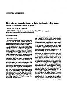
Figure S1. Low-magnification SEM image of ITO@Cu2S nanowire CE, in which Cu2S shell was prepared with SILAR method. The agglomerations of Cu2S particles in micrometer scale were found on the top of nanowire arrays.
2
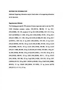
Figure S2. High-resolution TEM image of ITO@Cu2S a) before and b) after calcination.
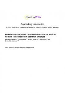
Figure S3. Photocurrent-voltage (J-V) curves of QDSSCs with calcinated (red) and uncalcinated (black) EX1-ITO@Cu2S CEs.
3
Table S1. Photovoltaic parameters of QDSSCs fabricated with calcinated and uncalcinated (black) EX1-ITO@Cu2S CEs
Counter electrode
Voc (V)
Jsc (mA cm-2)
FF (%)
η (%)
uncalcinated
0.528
11.68
51.03
3.15
calcinated
0.542
13.51
52.10
3.81
Figure S4. Statistical analysis on the power conversion efficiencies of QDSSCs with different CEs. 5 cells were used for each CE.
4
Figure S5. Statistical analysis on the power conversion efficiencies of QDSSCs with EX2-ITO@Cu2S CEs in different Cu2S shell thickness. 5 cells were used for each CE.
5
Figure S6. Equivalent circuits for fitting EIS of ITO@Cu2S CEs. Rh: sheet resistance of CE; Rct2: charge transfer resistance between CE and electrolyte; CPE: constant phase element of electrical double layer; Zw: Nernst diffusion impedance of electrolyte.
Table S2. EIS fitting parameters of dummy cells fabricated by EX2-ITO@Cu2S CEs with different Cu2S thickness
Thickness of Cu2S
CPE-T (mF)
CPE-P
Zw (Ω)
30nm
9.23
0.73
-
55nm
10.80
0.74
0.53
80nm
4.65
0.78
0.23
6