Supporting Information
Hydrogen and nitrogen codoping of anatase TiO2 for efficiency enhancement in organic solar cells Maria Vasilopoulou,1,* Nikolaos Kelaidis,2 Ermioni Polydorou,1,3 Anastasia Soultati,1 Dimitris Davazoglou,1 Panagiotis Argitis,1 Giorgos Papadimitropoulos,1 Dimitris Tsikritzis,4 Stella Kennou,4 Florian Auras,5 Dimitra G. Georgiadou,1,6 Stavros-Richard Christopoulos2 & Alexander Chroneos,2,7,*
1
Institute of Nanoscience and Nanotechnology (INN), National Center for Scientific Research Demokritos, 15310 Agia Paraskevi, Athens, Greece
2
Faculty of Engineering, Environment and Computing, Coventry University, Priory Street, Coventry CV1 5FB, United Kingdom 3
4
Department of Physics, University of Patras, 26504, Patras, Greece
Department of Chemical Engineering, University of Patras, 26504, Patras, Greece 5
Cavendish Laboratory, University of Cambridge, Cambridge CB3 0HE, United Kingdom
6
Department of Physics & Centre for Plastic Electronics, Imperial College, London SW7 2AZ, United Kingdom 7
Department of Materials, Imperial College, London SW7 2AZ, United Kingdom
*
[email protected],
[email protected]
S1
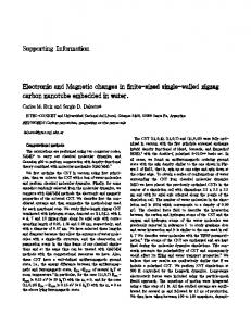
O-H
Ti-O
Transmittance (a. u.)
TiO2:N,H O-H
Ti-O
TiO2:H O-H
Ti-O
TiO2:N O-H
Ti-O
TiO2
4000 3500 3000 2500 2000 1500 1000 500 -1
Wavenumber (cm ) Figure S1. FTIR transmittance spectra of TiO2 samples either as-deposited (on silicon substrates) or annealed in nitrogen, hydrogen and forming gas (containing 90% nitrogen and 10% hydrogen) at 550 oC for 1 h. The thickness of the samples was ~40 nm.
S2
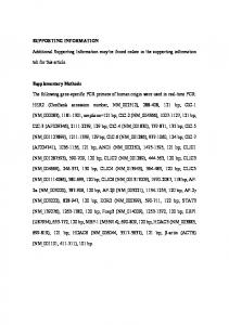
48
TiO2
40 36
Step height (nm)
Step height (nm)
44
32 28 24 20 16 12 8 4 0 230
232
234
236
238
240
242
244
246
52 48 44 40 36 32 28 24 20 16 12 8 4 0
TiO2:N
152
154
Scan length (m)
48 TiO2:H 44
48
40 36 32
40
44
28 24 20 16 12 8 4 0 264
158
160
162
164
(b)
Step height (nm)
Step height (nm)
(a)
156
Scan length (m)
TiO2:N,H
36 32 28 24 20 16 12 8 4
268
272
276
280
284
288
292
0
296
Scan length (m)
112 116 120 124 128 132 136 140 144 148
Scan length (m)
(c)
(d)
Figure S2. Profilometer thickness profile measurements of TiO2 samples.
S3
TiO2:N,H (101)
Intensity (a. u.)
TiO2:H (101)
TiO2:N (101)
TiO2 (101)
20
22
24
26
28
30
2xtheta (deg)
Figure S3. X-ray diffraction patterns of TiO2 samples with a thickness of ~40 nm. The samples were either as-deposited or annealed in nitrogen, hydrogen and forming gas at 550 oC for 1 h.
S4
200
(ahv)
1/2
(eV cm )
-1 1/2
180 160
TiO2
(Eg=3.20 eV)
TiO2:N
(Eg=3.10 eV)
TiO2:H
(Eg=3.14 eV)
TiO2:N,H (Eg=3.13 eV)
140 120 100 80 60 40 2.0
2.2
2.4
2.6
2.8
3.0
3.2
3.4
3.6
3.8
4.0
hv (eV)
Figure S4. Tauc plots, as derived from absorption measurements, for the estimation of bandgap for the different TiO2 samples.
Normalized intensity
1.0
XPS MgKa N1s
400.1 eV
TiO2: N TiO2:N,H
0.8 0.6 0.4 0.2 0.0 408
406
404 402
400
398
396 394
392
390
Binding energy (eV)
Figure S5. XPS N 1s peaks of TiO2 samples annealed in nitrogen and forming gas environments at 550 oC for 1 hour.
S5
1.1
Ti2p
Normalized intensity
1.0
458.7 eV
TiO2 TiO2:N
0.9
TiO2:H
0.8
TiO2:N,H
0.7 0.6
464.4 eV
0.5 0.4 0.3 0.2 0.1 468
466
464
462
460
458
456
454
Binding energy (eV)
Figure S6. XPS Ti 2p peaks of TiO2 samples annealed in different environments.
1.1
TiO2
O1s
Normalized intensity
1.0
TiO2:N TiO2:H
0.9
TiO2:N,H
0.8 0.7 0.6 0.5 0.4 0.3 534
533
532
531
530
529
528
527
526
Binding energy (eV)
Figure S7. XPS O 1s peaks of TiO2 samples annealed in different environments.
S6
12
-2
J (mA cm )
8 4
TiO2 TiO2:N TiO2:H TiO2:N,H
0 -4 -8
-12 -0.2 -0.1 0.0
0.1
0.2
0.3
0.4
Voltage (V)
0.5
0.6
0.7
0.8
Figure S8. Current density versus applied voltage (J-V) curves taken under 1.5 AM illumination of P3HT:PC70BM-based organic solar cells using N and H doped and codoped TiO2 ETLs. The annealing in different environments was performed at 550 o
C for 1 hour.
12
TiO2 o
-2
J (mA cm )
8 4
TiO2:N (300 C) o
TiO2:H (300 C) o
TiO2:N,H (300 C)
0 -4 -8 -12 -0.3 -0.2 -0.1 0.0 0.1 0.2 0.3 0.4 0.5 0.6 0.7 0.8 0.9
Voltage (V)
Figure S9. Current density versus applied voltage (J-V) curves taken under 1.5 AM illumination of P3HT:IC60BM-based organic solar cells using TiO2 ETLs. The TiO2 layers were either as-deposited or annealed in nitrogen, hydrogen and forming gas at 300 oC for 30 min.
S7