SUPPORTING INFORMATION Simulation and Experimental Assembly of DNA–Graft Copolymer Micelles with Controlled Morphology Zonghui Wei,§,‡ Yong Ren,†,ς,‡ John-Michael Williford,¶ Wei Qu,♮ Kevin Huang,|| Shirley Ng,† Hai-Quan Mao†,ς,* and Erik Luijten♮,#,δ,* Graduate Program in Applied Physics, Northwestern University, Evanston, Illinois 60208, United States † Department of Materials Science and Engineering, Whiting School of Engineering, Johns Hopkins University, Baltimore, Maryland 21218, United States ς Translational Tissue Engineering Center and and Whitaker Biomedical Engineering Institute, Johns Hopkins School of Medicine , Baltimore, Maryland 21287, United States ¶ Department of Biomedical Engineering, Johns Hopkins School of Medicine , Baltimore, Maryland 21205, United States ♮Department of Materials Science and Engineering, Northwestern University, Evanston, Illinois 60208, United States || Department of Chemical and Biomolecular Engineering, Johns Hopkins University, Baltimore, Maryland 21218, United States §
Department of Engineering Sciences and Applied Mathematics, Northwestern University, Evanston, Illinois 60208, United States δ Department of Physics and Astronomy, Northwestern University, Evanston, Illinois 60208, United States #
‡
These authors contributed equally to this work.
*
Corresponding authors. Email:
[email protected] and
[email protected]
Number of Pages: 6 Number of Supplementary Figures: 4 Number of Supplementary Tables: 1
S1
1. Simulation details 1.1 DNA bond stiffness As mentioned in the main text, an additional harmonic bond-angle potential was applied to the DNA to represent its intrinsic stiffness (see also Supplementary Information of Ref. 17). With this bond stiffness, the intrinsic persistence length of the DNA is 6.8σ, as determined from the exponential decay length of the bond-angle correlation function of a neutral, linear polymer with the same bond-angle potentialS1. As a result, the ratio of the intrinsic persistence length to the contour length was approximately three times larger than in the experiments, which we consider acceptable given the simplifications adopted in this semi-quantitative model. 1.2 Determination of polymer lengths In experiment, the ratio of the contour length of the PPA chain (LPPA) and the contour length of DNA (L) was 0.049. In simulation, we aimed to choose a PPA length that would give a ratio LPPA/L similar to experiment, while also being long enough to permit variation of the grafting density. However, too long PPA greatly restricts the shape of the plasmid DNA during condensation. Therefore, we chose a PPA length of 6 beads, resulting in LPPA/L = 0.075, close to the experimental value. The choice of PEG length requires additional considerations. In experiment, the plasmid DNA was long compared to PEG. Owing to computational limitations, we set the DNA length to 80 beads. As a result, it was not possible to attain a ratio between the contour length of the PEG chain (LPEG) and the contour length of the DNA similar to experiment. However, we considered this acceptable, since we aimed to elucidate the effect of PEG grafting density and chain length, not to realize a precise mapping of the experimental system. The PEG lengths were chosen such that LPEG/L and LPEG/LPPA exhibited trends similar to the experiments (Table S1).
S2
Table S1. Comparison of length ratios of PPA-g-PEG copolymers used in experiment and simulation. Experiment Copolymer PPA25K-gPEG5K PPA25K-gPEG2K PPA25K-gPEG0.8K
Simulation
Ratio* (LPEG/L)
Ratio (LPEG/LPPA)
Length of PPA
Length of PEG
Ratio (LPEG/L)
Ratio (LPEG/LPPA)
0.018
0.37
6
10
0.125
1.67
0.007
0.15
6
5
0.063
0.83
0.003
0.06
6
3
0.038
0.50
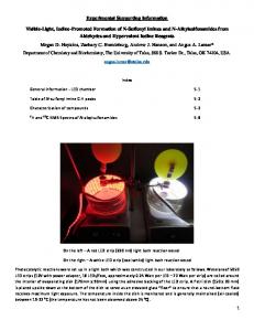
* Assuming that the actual monomer size of PPA is twice that of PEG. 1.3 Equilibration of the simulations The plasmid DNA chain, the copolymers, and the counterions initially were randomly placed in the simulation box. To accelerate the equilibration process, initially a shifted and truncated LJ interaction with cutoff 21/6σ was used as the only pairwise interaction between any two particles. After an equilibration period of 1.6 × 10³τ, the proper LJ interactions and all electrostatic interactions were switched on, followed by a second equilibration period of 2.45 × 10³τ. Then the simulation ran for a sampling period of 1.44 × 10⁶τ with a time step of 0.012τ. Fifteen independent runs were performed for each system to obtain accurate averaged properties. The distributions of the asphericity were averaged over the 15 systems, corresponding to 225,000 independent samples per parameter set. As shown in Fig. S1, the structure of the DNA frequently fluctuated between different states.
S3
PPA homopolymer
Asphericity
Asphericity
1.1 1.0 0.9 0.8 0.7 0.6 0.5 0.4 0.3 0.2 0.1 0
3.0×10⁵ 6.0×10⁵ 9.0×10⁵ 1.2×10⁶ 1.5×10⁶ Simulation Time(τ)
1.1 1.0 0.9 0.8 0.7 0.6 0.5 0.4 0.3 0.2 0.1 0
grafting density = 2%
0
grafting density = 1%
0
Asphericity
Asphericity
0
1.1 1.0 0.9 0.8 0.7 0.6 0.5 0.4 0.3 0.2 0.1 0
3.0×10⁵ 6.0×10⁵ 9.0×10⁵ 1.2×10⁶ 1.5×10⁶ Simulation Time(τ)
1.1 1.0 0.9 0.8 0.7 0.6 0.5 0.4 0.3 0.2 0.1 0
3.0×10⁵ 6.0×10⁵ 9.0×10⁵ 1.2×10⁶ 1.5×10⁶ Simulation Time(τ) grafting density = 4%
0
3.0×10⁵ 6.0×10⁵ 9.0×10⁵ 1.2×10⁶ 1.5×10⁶ Simulation Time(τ)
Fig. S1. Time evolution of the asphericity of the plasmid DNA within a PPA25k-g-
PEG5k/DNA micelle during one run, for different grafting densities. 1.4 Radius of gyration tensor For a set of particles, we define the radius-of-gyration tensor Q S2 with elements
1 N Qαβ = ∑ ⎡ ri,α − rj,α ⎤⎦ ⎡⎣ ri, β − rj, β ⎤⎦ , 2N 2 i, j=1 ⎣
(1)
where N = 80 is the number of beads representing the DNA, and ri represents the Cartesian coordinate of the ith bead, with α, β = 1, 2, 3 denoting the Cartesian components. 1.5 Determination of the micelle composition The micellar nanoparticle was an aggregate of DNA and copolymers bound by
S4
electrostatic interactions. We considered a copolymer as part of the micelle if at least one of its positively charged PPA beads was within a distance 2σ from a DNA bead. Our results were found to be insensitive to the precise choice of this cutoff.
2. Supplementary experimental results
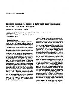
Fig. S2. TEM images of micelles prepared from PPA-g-PEG copolymers (a) with
different PEG molecular weight and PEG grafting density (MW of PPA 25 kDa); (b) with different PPA molecular weight and PEG grafting density (MW of PEG 5 kDa). *At 0% PEG grafting density, the particles are identical.
S5
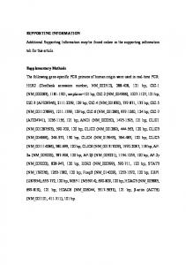
Fig. S3. TEM images of PPA25k-g-PEG2k/DNA micelles incubated with 10% FBS. The
PEG grafting densities were 1% (a), 2% (b), and 4% (c) respectively. Scale bars 500 nm. After incubation with 10% FBS, the micelle shapes did not exhibit a significant difference with the non-treated micelles (Figure 4b, 4e, and 4h). The background materials appear to be serum components adsorbed onto the TEM grids.
Fig. S4. Transfection efficiency of PPA-g-PEG/DNA micelles with different shapes in
HeLa cells (mean ± SD, n > 8).
Supporting References: (S1) Liao, Q.; Dobrynin, A. V.; Rubinstein, M. Macromolecules 2003, 36, 3386– 3398. (S2) Šolc, K. J. Chem. Phys. 1971, 55, 335–344.
S6