Apr 12, 2018 - The Li2SO4 solution was next added to the CMC gel under stirring ... Li2SO4 gel electrolyte using a toothpick, followed by removing the ...
Supporting Information
A Self-Healing Aqueous Lithium-Ion Battery Yang Zhao, Ye Zhang, Hao Sun, Xiaoli Dong, Jingyu Cao, Lie Wang, Yifan Xu, Jing Ren, Yunil Hwang, In Hyuk Son, Xianliang Huang, Yonggang Wang,* and Huisheng Peng* anie_201607951_sm_miscellaneous_information.pdf
Supporting Information
Experimental Section Preparation of the aligned carbon nanotube (CNT) sheet. Spinnable CNT array was synthesized by chemical vapor deposition in a tube furnace.[1] Fe (1.2 nm)/Al2O3 (3 nm) on a silicon substrate was used as the catalyst. For the catalyst, Al2O3 and Fe were successively deposited on silicon substrate by electron beam evaporation with rates of 2 and 0.5 Å s-1, respectively. The ethylene (90 sccm) was used as the carbon precursor and a mixture of Ar (400 sccm) and H2 (30 sccm) was used as the carrier gases. The growing time was 10 min at 740 oC to obtain the spinnable CNT array. The aligned CNT sheet was then continuously dry-drawn out of the CNT array through the use of a knife. Preparation of the self-healing polymer substrate. A modified Leibler’s method was used to synthesize the self-healing polymer.[2, 3] 20.43 g of DM-80 (85 wt% diacids and 10 wt% triacids, donated by Demand Chemical Co., Ltd, Shanghai) and 8.06 g of diethylenetriamine reacted at 160 oC for 12 h in a nitrogen atmosphere under mechanical stirring. The resulting product was dissolved in 95 mL of chloroform under heating. After cooling down, it was extracted with 95 mL of deionized water for three times, and then concentrated by rotary evaporation. 1.5 g urea was added to react with the product to synthesize the self-healing polymer at 140 oC for 5 h in argon. The polymer was then compressed to 0.5 mm thick substrates using a pre-cleaned glass slides. The preparation of LiMn2O4 (LMO) and LiTi2(PO4)3 (LTP) nanoparticles. LMO nanoparticles were synthesized by a solid-state method.[4] Li2CO3 and MnO2 were mixed together and reacted at 530 oC for 5 h, followed by heating at 700 oC for 24 h in air. Then the sample was cooled for 3 h. LTP nanoparticles were prepared by a sol-gel method.[5] An aqueous precursor containing Li2CO3, NH4H2PO4, and TiO2 was mixed with 100 mL of 2 wt % poly-vinyl-alcohol aqueous solution. The mixture was stirred at 80 oC until the water was evaporated and a white solid was formed. The product was placed in a porcelain boat and heated at 900 oC under N2 flow for 12 h at a rate of 5 oC/min in a tube furnace. Carbon coated LTP was prepared by chemical vapor S1
deposition to improve the electronic conductivity. The obtained product was transferred into a reaction tube to make a fluid-bed layer for reaction where the toluene vapor was carried by N2 through the tube at a flow rate of 1 L/min. The temperature was sequentially maintained at 700 oC and 900 oC each for 2 h. Fabrication of the self-healable aqueous lithium ion battery (LIB). 50 mg of either LMO or LTP nanoparticles were dispersed in 10 mL of ethanol under probe-sonication at 200 W for 20 min to prepare LMO and LTP suspensions with a concentration of 5 mg/mL. Aligned CNT sheets were continuously dry-drawn from a CNT array which was synthesized by chemical vapor deposition. 25 layers of CNT sheets were stacked onto a Teflon plate. 50 μL of LMO or LTP suspensions was dropped onto the CNT sheets on a hotplate at 80 oC, followed by covering with another five layers of CNT sheets. The resulting composite sheets were gently peeled from the Teflon plate and paved on the self-healing polymer substrate. The weight percentage of LMO and LTP in each film was the same of 85.6%. (It is necessary to increase the weight percentage of active particles to improve the specific capacity of the LIB. When the weight percentages of LMO and LTP were 85.6%, the nanoparticles were stable on the electrodes (Figures 1b and 1d). When the weight percentage further increase, the particles may peel off from the CNT sheets during the charge-discharge cycling. Therefore, the weight percentage of 85.6% had been mainly studied.) The randomly dispersed CNT composite film electrode was prepared by a vacuum filtration method and then paved on the self-healing polymer substrate. 3 g of CMC was swollen in 60 mL of deionized water for 60 min. It was then kept at 80 oC under vigorous mechanical stirring for 3 h to form a gel. 14.6 g Li2SO4·H2O was dissolved in 36 mL deionized water. The Li2SO4 solution was next added to the CMC gel under stirring and heating for 1 h to produce a homogeneous aqueous Li2SO4 gel electrolyte. Both CNT/LMO/CNT and CNT/LTP/CNT sheet electrodes were further coated with Li2SO4 gel electrolyte using a toothpick, followed by removing the bubbles under vacuum at room temperature (~25 C). The two electrodes were gently pressed together to form the self-healable aqueous LIB. The CNT sheets of two electrodes were extracted by Cu foils for the convenience of the electrical measurements. The electrodes and LIBs were cut under a vertical or parallel direction in relative to the CNT-aligned direction. For the healing experiments, to prevent short-circuit during the healing process, the two broken parts were firstly put on the flat table in a S2
line to examine the integrity of the fracture surfaces. Then the two broken parts were pushed together in the same plane and then contacted for seconds to make sure the geometrical matching between the broken parts. Once the short-circuit takes place, it is probably caused by the part contact of a few CNTs between two electrodes. The battery can be recovered to normal function by separating the connection of the upper and lower CNTs in the electrolyte and then charging the LIB again. The specific capacity (C) of the self-healable aqueous LIB was calculated from the equation of C = (I×Δt)/m, where I, Δt, and m correspond to the discharge current, discharge time and the weight of CNT/LMO/CNT film, respectively. The energy density of the self-healable LIB was calculated from Em = (I×U×t)/m or Ev = (I×U×t)/v, and the power density was obtained from Pm = (I×U)/m or Pv = (I×U)/v, where I, U, t, m and v represent the discharge current, average operating voltage, discharge time, total mass and volume of the CNT/LMO/CNT and CNT/LTP/CNT films, respectively. The structures were characterized by scanning electron microscopy (SEM, Hitachi FE-SEM S-4800), X-ray diffraction (XRD, Bruker AXSD8) and optical microscopy (Olympus BX51). The resistance was measured with a Keithley Model 2400 Source Meter. The stress-strain curves were conducted with a Shimadzu Table-Top Universal Testing Instrument with a strain rate of 100 mm/min. 1H nuclear magnetic resonance (NMR) spectra were recorded from a Bruker 400 MHz spectrometer. The elemental analysis of the self-healing polymer was conducted at a CHNS elemental analyzer (VARIO ELIII). The histogram of the particle sizes was conducted with a Nano particle
size-Zeta
potential
analyzer
(Zetasizer
Nano).
The
galvanostatic
charge-discharge, rate capability and cyclic performance of the aqueous LIBs were measured at an Arbin electrochemical station (MSTAT-5 V/10 mA/16Ch). The cyclic voltammetry (CV) and charge-discharge curves of the half LIB were measured with three-electrode cells in 1 mol/L Li2SO4 solution through an electrochemical workstation (CHI 660a). The used reference and counter electrodes were saturated calomel electrode and excessive activated carbon, respectively. Differential scanning calorimeter (DSC) curve was conducted at a heating rate of 10 °C/min under nitrogen atmosphere (DSC Q2000). The photographs were taken by a camera (Nikon, J1). The bending measurements were performed at a table-top universal testing instrument (HY-0350).
S3
Figure S1. Photographs of the free-standing self-healing polymer substrate.
S4
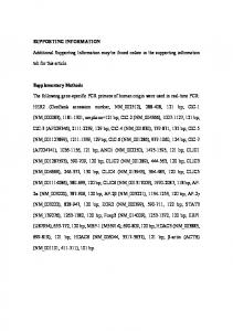
Figure S2. Chemical structure of the self-healing polymer.
S5
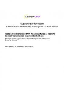
Figure S3. 1H NMR spectra of the reactants and self-healing polymer. After the reaction, the amino and carboxyl groups were changed to amide groups.
S6
Table S1. The elemental analysis results of the self-healing polymer. The temperatures of combustion tube and reduction tube were 1150 and 850 oC, respectively. Element
N
C
H
Weight percentage (%)
8.044
69.76
19.07
S7
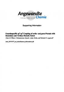
Figure S4. SEM image of a spinnable CNT array by side view.
S8
Figure S5. Photographs of the procedure for fabricating the aligned CNT sheet from a spinnable CNT array.
S9
Figure S6. SEM image of an aligned carbon nanotube (CNT) sheet drawn from CNT array.
S10
Figure S7. SEM image of LMO nanoparticles.
S11
Figure S8. SEM image of LTP nanoparticles.
S12
Figure S9. The histogram of the particle sizes of LMO (a) and LTP (b) particles.
S13
Figure S10. XRD pattern of LMO nanoparticles.
S14
Figure S11. XRD pattern of LTP nanoparticles.
S15
Figure S12. SEM image of the aligned CNT sheets covered with LMO particles.
S16
Figure S13. SEM image of the aligned CNT sheets covered with LTP particles.
S17
Figure S14. Galvanostatic charge-discharge curves of the CNT/LMO/CNT half LIB at different current densities tested in 1 mol/L Li2SO4 solution.
S18
Figure S15. Galvanostatic charge-discharge curves of the CNT/LTP/CNT half LIB at different current densities tested in 1 mol/L Li2SO4 solution.
S19
Figure S16. CV curve of the CNT/LMO/CNT half battery at a scan rate of 0.3 mV/s tested in 1 mol/L Li2SO4 solution.
S20
Figure S17. CV curve of the CNT/LTP/CNT half battery at a scan rate of 0.3 mV/s tested in 1 mol/L Li2SO4 solution.
S21
Figure S18. Galvanostatic charge-discharge curves of the full LIB at different current densities tested in 1 mol/L Li2SO4 solution.
S22
Figure S19. Cyclic performance of the full LIB at a current density of 0.5 A/g tested in 1 mol/L Li2SO4 solution.
S23
Figure S20. DSC curve of the self-healing polymer substrate.
S24
Figure S21. Optical micrographs of the self-healing substrate after cutting (a) and self-healing (b).
S25
Figure S22. Stress-strain curve of the self-healing polymer.
S26
Figure S23. Photographs of the self-healing electrode at different bending or twisting states.
S27
Figure S24. Photographs of the self-healing electrode at bending and twisting states after the cutting-healing processes.
S28
Figure S25. SEM images of the polymer substrate covered with only aligned CNTs before breaking (a), after cutting (b) and self-healing (c).
S29
Figure S26. Electrical resistances of the self-healing electrode before breaking (a), after cutting (b) and self-healing (c).
S30
Figure S27. Photographs of the self-healing electrodes before cutting (a, c and e) and after cutting under vertical (b), parallel (d) and 45o (f) directions in relative to the CNT-aligned direction.
S31
Figure S28. Electrical resistances of the self-healing electrodes during ten cycles of cutting-healing processes under 45o cutting (in relative to the CNT-aligned direction).
S32
Figure S29. The comparison of the self-healing performance between aligned CNT composite sheet and randomly dispersed CNT composite film electrodes. R0 and R correspond to the resistances before breaking and after self-healing, respectively.
S33
Figure S30. Photographs of the self-healable aqueous LIB.
S34
Figure S31. Alternating current impedance spectra of the Li2SO4/CMC gel electrolyte at the frequency range from 0.01 Hz to 100 kHz. The ionic conductivity of the Li2SO4/CMC gel electrolyte was calculated by the equation of σ = l/(A×R), where σ, l, A and R represent the ionic conductivity, the thickness, the area, and the resistance of gel electrolyte between two stainless plates, respectively. The resistance was 7.4 Ω and the thickness and area of the electrolyte were 0.9 cm and 1 cm2, respectively. Therefore, the ionic conductivity of the hydrogel electrolyte was calculated as 0.12 S/cm.
S35
Figure S32. SEM image of the self-healing electrode after partly coating the gel electrolyte. There was no bubble between the electrode and gel electrolyte with a good contact after the vacuum treatment. The good contact between the electrode and gel electrolyte could be further proved by the decent electrochemical performance of the aqueous LIB in Figure 3b.
S36
Figure S33. Stress-strain curves of the self-healable aqueous LIBs before and after the cutting-healing cycles.
S37
Figure S34. The safety test of the self-healable aqueous LIB. a) Photograph of the self-healable LIB powering a red LED lamp. b) and c) Photographs of the self-healable LIB before and being drilled through by a sharp knife. d) Photograph of the self-healable LIB powering a red LED lamp after being drilled through and healing.
S38
Figure S35. Energy and power densities of the self-healable aqueous LIB compared with previous reported self-healable energy storage devices.
S39
Figure S36. Volumetric energy and power densities of the self-healable aqueous LIB compared with previous reported conventional batteries LTO/LMO LIB thin-film battery
[10]
[9]
and Li
.
S40
References for the Supporting Information [S1]
L. Qiu, S. He, J. Yang, J. Deng, H. Peng, Small 2016, 12, 2419-2424.
[S2]
P. Cordier, F. Tournilhac, C. Soulié-Ziakovic, L. Leibler, Nature 2008, 451, 977-980.
[S3]
H. Sun, X. You, Y. Jiang, G. Guan, X. Fang, J. Deng, P. Chen, Y. Luo, H. Peng, Angew. Chem. Int. Ed. 2014, 53, 9526-9531.
[S4]
Y. Y. Liang, S. J. Bao, B. L. He, W. J. Zhou, H. L. Li, J. Electrochem. Soc. 2005, 152, A2030-A2034.
[S5]
L. Chen, J. Liu, Z. Guo, Y. Wang, C. Wang, Y. Xia, J. Electrochem. Soc. 2016, 163, A904-A910.
[S6]
H. Sun, X. You, Y. Jiang, G. Guan, X. Fang, J. Deng, P. Chen, Y. Luo, H. Peng, Angew. Chem. Int. Ed. 2014, 53, 9526-9531.
[S7]
H. Wang, B. Zhu, W. Jiang, Y. Yang, W. R. Leow, H. Wang, X. Chen, Adv. Mater. 2014, 26, 3638-3643.
[S8]
T. Trivedi, D. Bhattacharjya, J. Yu, A. Kumar, ChemSusChem 2015, 8, 3294-3303.
[S9]
Y. Yang, S. Jeong, L. Hu, H. Wu, S. W. Lee, Y. Cui, Proc. Natl. Acad. Sci. USA 2011, 108, 13013-13018.
[S10]
D. Pech, M. Brunet, H. Durou, P. Huang, V. Mochalin, Y. Gogotsi, P. L. Taberna, P. Simon, Nat. Nanotechnol. 2010, 5, 651-654.
S41