J Mol Model (2008) 14:1183–1189 DOI 10.1007/s00894-008-0369-x
ORIGINAL PAPER
Surface and interlayer structure of vermiculite intercalated with methyl viologen Lenka Kulhánková & Pavla Čapková & Veronika Ramirez De Valle & Juan Poyato & Jose Luis Pérez-Rodríguez & Anton Lerf
Received: 16 April 2008 / Accepted: 22 September 2008 / Published online: 16 October 2008 # Springer-Verlag 2008
Abstract Molecular modeling using empirical force field revealed the differences between the surface and interlayer arrangement of the dye guest molecules in vermiculite intercalated with the divalent methyl viologen cation (MV2+). Conformation and anchoring of MV2+ cations on the silicate layer in the interlayer space of vermiculite host structure is different from that on the crystal surface. A preferential position has been found for the anchoring of guests on the silicate layer. Anyway the arrangement of guests in the interlayer space as well as on the crystal surface exhibits a high degree of disorder due to a certain flexibility in guest molecules arrangement and first of all due to the presence of water molecules in the interlayer space. The presence of water disturbs not only the regularity in guest L. Kulhánková (*) Faculty of Metallurgy and Materials Engineering, VŠB-Technical University Ostrava, 17. listopadu 15, 70833 Ostrava, Czech Republic e-mail:
[email protected] P. Čapková Nanotechnology Centre, VŠB-Technical University Ostrava, 17. listopadu 15, 70833 Ostrava, Czech Republic V. Ramirez De Valle : J. Poyato : J. L. Pérez-Rodríguez Instituto de Ciencia de Materiales de Sevilla, Consejo Superior de Investigaciones, Científicas-Universidad de Sevilla, C/Américo Vespucio 49, 41092 Sevilla, Spain A. Lerf Walter-Meißner Institut, Bayerische Akademie der Wissenschaften, Walther-Meißner-Straße 8, 85748 Garching, Germany
positions and orientations but also in conformation of guest molecules in the interlayer space of the host structure. Keywords Molecular modeling . Methyl viologen . MV2+ -vermiculite
Introduction The structure of intercalation compounds is a result of competition of many factors determining the host-guest interaction [1]. The structure analysis of intercalated layer compounds using diffraction method is usually obstructed by a disorder in the arrangement of guest molecules in the interlayer space and consequent disorder in layer stacking. This disorder has especially strong influence in case of optical properties. The spectral behavior of organic dyes is strongly affected by their intercalation and/or by surface anchoring on a host crystal structure [2–9]. Intercalation thus offers the tuning of spectral properties by choosing a suitable host-guest combination. Thanks to their transparency, layer silicates represent very convenient host matrix for intercalation of organic dyes. Fluorescence of dye molecules intercalated in layer silicates studied in recent years [9–10] showed a strong dependence on the silicate layer charge. The phyllosilicate layer charge affects the intercalation behavior, the guest concentration and the guest arrangement in the interlayer space. Large structural disorder and inhomogenity results in the large broadening of fluorescence bands observed in intercalated phyllosilicates [9–11]. The structural disorder is not just caused by incomplete ordering of the intercalated species, but is a genuine feature of the phyllosilicates used for intercalation, especially those of the smectite group. In contrast, vermiculites occur mostly in large crystalline flakes, and thus have a much lower
1184
degree of disorder. In addition vermiculites are phyllossilicates with a relatively high layer charge on the silicate layer mostly localized in the tetrahedral sheet and, thus the host-guest interaction is much stronger than for intercalated smectites. Consequently many intercalated vermiculite structures exhibit 3-dimensional ordering [12–18]. That is why we have chosen vermiculite as a good candidate for the intercalation of organic dyes in search for a suitable host-guest combination in dye/clay nanocomposite design. The aim of this work is to analyze the structure of MV2+ vermiculite using combination of molecular modeling with X-ray powder diffraction as the necessary prerequisite for understanding the structure-properties relationship and consequently for design of materials based on dye-clay intercalates.
Experiment Preparation of MV2+ - vermiculite samples and x-ray diffraction measurement The vermiculites under study have been found as large flakes with centimeter diameters. For the redox reactions
J Mol Model (2008) 14:1183–1189
Fig. 2 Fragment of the intercalated structure of MV2+ -vermiculite; side view, showing the orientation of guests in the interlayer space. One can see the rotation of ring planes in guest molecules and free rotation of ending methyl groups
we used powder samples with a particle size < 80 μm obtained by grinding in a Knife-mill (Netzsch ZSM-1, Germany). The structural formula of the starting material was: Mg 0.26 [(Si 2.83 Al 1.17 ) (Mg 2.01 Al 0.2 Fe 3+ 0.4 Fe 2+ 0.16Ti0.14)O10(OH)2] for the Ojén vermiculite [19]. The sodium form of the Ojén vermiculite was obtained by repeated soaking of the Mg-vermiculites in 1M solutions of NaCl and stirring at room temperature. The Na-vermiculites were converted into the MV2+ form by repeated contact with a 0.1M MV2+ - chloride solution and stirring at 60°C. After ion exchange the samples were washed with distilled water until the supernatant solution was free of chloride ions (tested with AgNO3 solution). X-ray powder diffraction measurements have been carried out on powder diffractometer (Philips X’Pert) in Bragg-Brentano geometry using CuKα1 radiation. The measured powder pattern is in Fig. 1, showing the diffraction profile typical for layered structure with partially disordered layer stacking that means the relatively sharp basal reflection and large broadening of non-basal reflections. This disorder in layer stacking in the case of intercalated layered structures was a result of the disorder in arrangement of guest molecules in the interlayer space. The measured basal spacing obtained from x-ray powder diffraction was 13.06 Å. Modeling strategy The initial model of the host vermiculite layer was built in Materials Studio (Crystal builder module) using structure
Fig. 1 Measured XRD pattern for MV2+ - Ojén-vermiculite
Fig. 3 Conformation of the guest molecule MV2+ in the interlayer space with the rotation of ring planes around the central C-C bond
J Mol Model (2008) 14:1183–1189
1185
data published by Slade et al. [20]. To create the supercell of reasonable size for calculations the structure formula was approximated by: (Si34Al14) (Mg25 Fe3+ 5 Fe2+ 2 Al2Ti2 O120 (OH)24 for the supercell 3a x 2b x 1c (six-fold single cell). The basal spacing in the initial model was set up to 1.3 nm according to the basal spacing obtained from X-ray powder diffraction. Double layered supercell 3a x 2b x 2c was taken as a starting model of the host matrix for modeling of intercalate, where the silicate layer charge was compensated by three methyl viologen guest cations MV2+ per one silicate layer in 3a x 2b x 2c double layered supercell. Starting models of 3D-crystal structure have been generated by the systematic grid search (systematic changes of positions and orientations of guests). After preliminary fast energy minimization a series of initial models with various positions and orientations of MV2+ guests and with variable water content in the interlayer space has been chosen for the final structure optimization. The same strategy was used to generate the starting models of Fig. 4 a, b: Two possible arrangements of guests on the phyllosilicate layer with nearly the same crystal energy, keeping the same preferential position of guests with respect to the host layer
a)
b)
surface layer. The 2D-periodical model of the surface was constructed as a sandwich consisting of two silicate layers, where the interlayer structure was the same as in 3D models and the charge compensation of the lower layer was guaranteed with Na+ cations placed in the bottom of the surface layer model. Geometry optimization was carried out in Materials studio software package using Universal force field [21]. Constraints during energy minimization have been chosen respecting the rigidity of the silicate layers, confirmed by IR spectroscopy [22], i.e.: Cell optimization was carried out with fixed lattice parameters a, b and γ.
Results of structure analysis The optimization of 3D-periodical structure led to the arrangement of MV2+ in the interlayer space with the long axis of the molecules parallel with the phyllosilicate layers (see Fig. 2). The ring planes in the guest molecules have
1186
J Mol Model (2008) 14:1183–1189
been found twisted around the central C-C bond at about 45° (see Fig. 3). Geometry optimization led to several structure models with nearly the same total crystal energy and with different arrangement of guests in the interlayer space. This result is in agreement with the measured diffraction pattern, which exhibits the large broadening of diffraction profiles. The common feature of all the optimized models was the preferential position of the guest molecules on the phyllosilicate layers. Two examples of the guest arrangements are illustrated in Figs. 4a and b, where both models 4a and 4b exhibit
Fig. 5 a, b: The presence of water (a) disturbing the guest arrangement in the interlayer space (b)
a)
b)
nearly the same crystal energy (-271 604 kcal and –271 597 kcal per one 3a x 2b x 2c supercell). In both models one can see the similarity in guest position on the silicate layer. In the Fig. 4 one can see the upper view of the structure in projection onto the basal plane, where for the clarity only the guest layer and one silicate layer are visualized. As one can see guest molecules prefer the position with the central C-C bond located just over the surface oxygen atom on the lower silicate layer and just under the surface oxygen atom on the upper silicate layer. The ring planes are tilted with respect to the silicate
J Mol Model (2008) 14:1183–1189
1187
layers, oriented with two bottom hydrogen atoms pointing to the lower silicate layer and the two top hydrogen atoms in the tilted ring pointing to the upper silicate layer (see Fig. 4a,b). The basal spacing for calculated models without water in the interlayer space is within the range 12.26–12.35 Ǻ. Comparison of a calculated basal spacing with the experimental value 13.06 Ǻ points to a presence of water in the interlayer space, which leads to an increase of interlayer distance in calculated models. Gradual addition of water molecules into the interlayer space increased the basal spacing from 12.26 Ǻ up to 13 Ǻ for 12 H2O molecules per one 3a x 2b x 2c double layered supercell. For this water content the calculated basal spacing agrees with the experimental value 13.06 Ǻ. Figure 5 shows Fig. 6 a, b: Side view of surface layer (a) and top view of guest position on the silicate layer surface (b) with methyl groups residing in pseudohexagonal cavities
a)
b)
the effect of water on the arrangement of guest molecules in the intercalated structure. The presence of water disturbs the positional and orientational ordering of interlayer guest structure and even the guest conformation. This explains the broadening of basal diffraction lines and disorder in layer stacking, observable as a large broadening of non basal diffraction line profiles (see Fig. 1). The water molecules prefer the position adjacent to the silicate layers. As there is still a lot of empty space even in the fully exchanged Ojén vermiculite, water molecules located in the vacant interlayer space (between guest MV2+ cations) can reside also in the middle of the interlayer space in the guest layer (see Fig. 5b). The surface guest structure obtained by modeling differs from that in the interlayer space. First of all the molecular
1188
conformation of MV2+ guests anchored on the surface is planar (see Fig. 6a), what is understandable regarding the interaction of guest molecule with one host layer only. The position preferred by MV2+ guests on the surface differs from that in the interlayer space. Methyl groups tend to sit in the pseudo-hexagonal cavity in the silicate layer, as one can see in Fig. 6b. The same conclusion about the effect of water molecules can be made for the surface guest structure, i.e., the presence of water in higher concentration affects the guests ordering.
J Mol Model (2008) 14:1183–1189
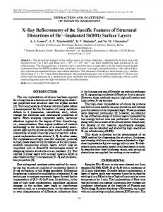
Experimental diffraction
Discussion and conclusions Structure analysis based on combination of X-ray powder diffraction and molecular modeling showed the tendency to MV2+ guest ordering in vermiculite host structure. However the concentration of guest cations necessary for the compensation of vermiculite layer charge is too low to fill completely the interlayer space. Consequently there is certain flexibility in guest arrangement, resulting in a certain degree of structural disorder. A second consequence of the low guest concentration is a large empty space in the interlayer, which is available for water sorption. Interlayer water disturbs the tendency of guests ordering and affects also their conformation. These conclusions from modeling are in good agreement with the experimental diffraction pattern (see Fig. 1), where the broadening of non-basal reflections indicates partially disordered layer stacking. Anyway a certain degree of ordering in layer stacking is still preserved in real samples of MV2+ vermiculite, as non-basal reflections are smoothed but still observable. This is the significant difference between the intercalated vermiculites and montmorillonites. In the case of montmorillonites intercalated with organic dyes there are usually only one or two basal reflections observable with typical hk- bands indicating the totally disordered stacking of the phyllosilicate layers. Comparing the calculated and experimental diffraction pattern in the Fig. 7 one can see a good agreement as to the peak positions and intensity ratio for basal reflections. However the profiles of diffraction lines for real sample exhibit a large broadening as a result of structural disorder and fluctuating water content. Figure 7 shows one example of calculated diffraction pattern for one optimized structure chosen from a set of calculated models with nearly the same crystal energy, but slightly different arrangement of guests and water molecules. For comparison of calculated diffractogram with the experimental pattern we have to consider an average pattern calculated for all optimized structures with nearly the same crystal energy. We have to take into account the effect of fluctuating water content and slight disorder in interlayer structure on the mutual intensity ratio of diffraction lines.
Calculated diffraction
Fig. 7 Diffraction pattern for one of the calculated models of MV2+ vermiculite. Comparing with the diffraction pattern of real sample one can see a good agreement as to the peak positions and intensity ratio for basal reflections. Anyway the profiles of diffraction lines for real sample exhibit a large broadening as a result of structural disorder and fluctuating water content
Present results also showed the possibility to estimate the interlayer water content by molecular modeling. The difference in surface and interlayer guests arrangement found in the present work is consistent with the results of our recent work on rhodamine B intercalated in montmorillonite [11]. Mixing surface and interlayer structure affects the physical properties, which are strongly dependent on structural ordering. Therefore a host matrix for optically active molecules where the guests will be anchored only on the crystal surface seems to be more promising for design of materials with homogeneous structure and optical properties. Acknowledgements This work was supported by the grant of Ministry of Education in Czech Republic, grant no: MSM 6198910016 and Grant Agency of Czech Republic GAČR grant no: 205/08/0869. We acknowledge also the financial support of the German Academic Exchange Service (DAAD) in the framework of the Actiones Integradas Program. The financial support from project MAT 2005–04838 of the Spanish Government is also acknowledged.
J Mol Model (2008) 14:1183–1189
References
1. Čapková P, Schenk H (2003) J Incl Phenom Macrocycl Chem 47:1–10 doi:10.1023/B:JIPH.0000003826.01697.42 2. Ogawa M, Kimura H, Kuroda K, Kato C (1996) Clay Sci 10:57–65 3. Ogawa M, Kuroda K (1995) Chem Rev 95:399–438 doi:10.1021/ cr00034a005 4. Lerf A, Čapková P (2004) Dye/inorganic nanocomposites. In: Nalva HS (ed) Encyclopedia of nanoscience and nanotechnology, vol. 2. American Scientific publishers, Stevenson Ranch, CA, USA, pp 639–694 5. Bujdák J, Iyi N, Fujita N (2002) Clay Miner 37:121–133 doi:10.1180/0009855023710022 6. Bujdák J, Iyi N, Kaneko Y, Sasai R (2003) Clay Miner 38:561– 572 doi:10.1180/0009855033840115 7. Bujdák J, Janek M, Madejová J, Komadel P (2001) Clays Clay Miner 49:244 doi:10.1346/CCMN.2001.0490307 8. Yariv S, Lurie D (1971) Isr J Chem 9:537–552 9. Klika Z, Čapková P, Horáková P, Valášková M, Malý P, Macháň R et al (2007) J Interface Colloid Sci 311:14–23 doi:10.1016/j. jcis.2007.02.034 10. Martynková GS, Kulhánková L, Malý P, Čapková P (2008) J Nanosci Nanotechnol 8:2069–2074 doi:10.1166/jnn.2008.058
1189 11. Čapková P, Malý P, Pospíšil M, Klika Z, Weissmanová H, Weiss Z (2004) J Colloid Interface Sci 277:128–137 doi:10.1016/j. jcis.2004.03.035 12. Slade PG, Raupach M, Emerson WW (1978) Clays Clay Miner ISSN/0009–8604 13. Faridi AV, Guggenheim S (1997) Clays Clay Miner 45:859–866 doi:10.1346/CCMN.1997.0450610 14. Iglesias JE, Steinfink H (1974) Clays Clay Miner ISSN/0009–8604 15. Slade PG, Stone PA (1983) Clays Clay Miner 31:200–206 doi:10.1346/CCMN.1983.0310305 16. Slade PG, Gates WP (2004) Clays Clay Miner 52:204–211 doi:10.1346/CCMN.2004.0520206 17. Slade PG, Gates WP (2007) Clays Clay Miner 55:131–139 doi:10.1346/CCMN.2007.0550202 18. Slade PG, Gates WP (2004) Appl Clay Sci 25:93–101 doi:10.1016/j.clay.2003.07.007 19. Pérez-Rodríguez JL, Carrera F, Pérez-Maqueda LA, Poyato J (2002) Nanotechnology 13:382–387 doi:10.1088/0957–4484/13/3/328 20. Slade PG, Stone PA, Radoslovich EW (1985) Clays Clay Miner 33:51–61 doi:10.1346/CCMN.1985.0330106 21. Rappe AK, Casewit CJ, Colwell KS, Goddard WA, Skiff WM (1992) J Am Chem Soc 114:10024–10035 doi:10.1021/ja00051a040 22. Čapková P, Pospíšil M, Miehé-Brendlé J, Trchová M, Weiss Z, Le Dred R (2000) J Mol Model 6:600–607 doi:10.1007/ s0089400060600