the ferroelectric thin film with the signal processing circuitry, an IC compatible process has to be ... bonding between the sensing element and the signal processing circuit. ... Thermal detectors include bolometers and pyroelectric detectors. ... These include chemical solution deposition, such as sol-gel or metal-organic ...
Surface Micromachining of Uncooled Infrared Imaging Array Using Anisotropic Conductive Film Weiguo Liu, Lingling Sun, Weiguang Zhu, Ooi Kiang Tan Microelectronics Center, School of Electrical and Electronic Engineering Nanyang Technological University, Singapore 639798 ABSTRACT
Micromachining processes have been extensively adapted in developing uncooled infrared imaging array. One of the most important sensing materials in the array is ferroelectric thin film. To integrate the ferroelectric thin film with the signal processing circuitry, an IC compatible process has to be applied. Various methods have been successfully used to prepare high quality oxide ferroelectric thin films. Unfortunately, not all of the methods are compatible with a standard CMOS process. None of them can optimize the ferroelectric thin film after it has been deposited onto IC chip due to high heat treatment temperature. A Flip-Chip Transfer (FCT) method is proposed here to optimize the ferroelectric thin film separately with the IC chip. Doing so, any necessary measure could be taken to optimize the performance of the ferroelectric thin film. After that, anisotropic conductive film (ACF) is applied between the ferroelectric thin film and the IC chip to establish interconnection and mechanical bonding between the sensing element and the signal processing circuit. Micromachining process is then applied to remove the substrate, usually Si, on which the sensing material is deposited. A 128x1 linear pyroelectric infrared imaging array is being fabricated. Keywords: Surface micromachining; Flip-chip transfer; anisotropic conductive film; Pyroelectric infrared imaging array 1. INTRODUCTION
Thermal detectors include bolometers and pyroelectric detectors. These detectors typically operated at room temperature (uncooled) and do not require cryogenic cooling. Thermal detectors today show many good characteristics, such as fast response, low noise, low power consumption, and moderate sensitivity at ambient temperature. The detector signal is related to the temperature of the detector material, which is altered because of incident thermal radiation. Both pyroelectric and bolometer arrays are being developed and at present there is no clear preferred technology. To improve the sensitivity, thermal structure of the detector plays an important role. Different configurations of the uncooled infrared imaging arrays have been proposed based on different silicon micromachining techniques. Micro-bridge and micro-air-gap structures have been realized using Si surface micromachining.1, 2 Micro-bridge structure has been proved to be successful for the resistive bolometers, in which, the deposition of resistor array could be carried-out at a temperature compatible with a standard CMOS process. To improve the levels of performance of the bolometer arrays, materials with higher temperature coefficient of resistance (TCR) are required. Recently, high temperature superconductors and colossal magneto-resistive materials are examined. These materials may be deposited at a temperature not compatible with the standard CMOS process. Among pyroelectric materials, ferroelectric thin films are the most promising. When ferroelectric thin films are used as thermal sensing materials, one important factor has to be considered in the fabrication of the arrays is the compatibility of the micro-fabrication process of the device with the CMOS processes.
In this paper, we propose a new process to provide the opportunity to optimize the thermal sensing materials for either bolometer or pyroelectric arrays separately with the CMOS process. As an example, pyroelectric array with ferroelectric thin film as sensing material is being developed using the proposed flip-chip transfer (FCT) surface micromachining technique. This method is applicable to the fabrication of both the bolometer and the pyroelectric uncooled infrared imaging arrays. 2. FERROELECTRIC THIN FILM PREPARATION
Ferroelectric thin films have been proven promising materials in developing pyroelectric uncooled infrared imaging arrays. Many techniques have been researched for ferroelectric thin film deposition. These include chemical solution deposition, such as sol-gel or metal-organic deposition, sputtering, pulsed laser ablation deposition and metal-organic chemical vapor deposition (MOCVD). Each of the methods has its own advantages and disadvantages. High deposition or post-deposition annealing temperature makes these methods not compatible with a standard CMOS process. Efforts have been paid either to reduce the deposition temperature or find a novel integration process to avoid the impact of the high temperature on the CMOS process. Recent progress in MOCVD deposition of ferroelectric lead zirconate titanate (PZT) thin films at low-temperature is quite encouraging. 3 But unfortunately, not all ferroelectric thin films could be deposited at a temperature lower than 450oC, which is the upper limit on the ferroelectric thin film process temperature required by the CMOS process. Ferroelectric thin films deposited at relatively low temperatures show poor crystallinity and thus poor pyroelectric property. To optimize the properties of the ferroelectric thin films, high deposition temperature or high post-deposition annealing temperature is desirable. In this paper we show that dielectric and pyroelectric properties of lead zirconate titanate (PZT) and lead titanate (PT) multilayered thin films can be optimized at a temperature around 600oC. Substrate used in this work is n-silicon wafer that is first thermally oxidized to form 500nm SiO2 on both sides of it. 200nm Si3N4 is then deposited onto both sides of the wafer by LPCVD method. On the front side, 50nm Ti is deposited followed by 150nm Pt to serve as bottom electrode for the PZT and PT thin film. Spin-coating process of PZT and PT thin film is performed on the top of the Pt thin films. Moisture-insensitive solid PZT and PT precursors are prepared from partially stabilized titanium isopropoxide, lead acetate trihydrate and zirconium acetylacetone without any solvent. The solid precursors are dissolved in 2-methoxyethanol to form sols. The sols are used to prepare PZT and PT thin films. Chemicals used in the experiments are acetylacetone (Fluka Scientific), lead acetate trihydrate (Riedel-de Haën), zirconium acetylacetonate (Fluka Scientific), and titanium isopropoxide (Sigma-Aldrich). After the precursor is formed, 2-methoxyethanol is used as solvent to prepare PZT and PT sols with different concentrations. The thin films are prepared with spin-coating process at 3000rpm for 30 seconds. The spin-coating process is repeated till desired thickness is reached. Each layer is pre-baked at certain temperature for 2 minutes by putting the film directly into pre-heated Thermolyne 47900 furnace after the film is spin-coated. Annealing of the films is carried out at 600oC for 30 minutes. Details of the thin film preparation process was reported elsewhere.4 Multilayered PZT/PT thin films are prepared by alternatively depositing PZT and PT layer for 5 times, and finally a PZT layer is deposited with the PZT as the first and the final layer in the multilayered thin film. In addition, PZT thin films alone are also prepared by repeating the spin-coating steps for 11 times. The fired thickness of each layer of PZT or PT thin film in one spin-coating step is about 50 nm, thus, total thickness for both the PZT/PT and the PZT thin film is about the same of 550 nm.
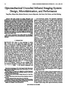
We find that prefer orientation of PZT thin films is strongly influenced by the pre-baking temperature of the films when they are deposited. Results are shown in figure 1. If the pre-baking temperature is lower than 500oC, randomly oriented films are obtained (figure 1(a)). When the film is pre-baked at 500oC, (001) prefer oriented film is obtained as shown in figure 1(b).
50 00 50
Pt
(211 )
00
(102 )
460 C
o
500 C
(002 ) (200 )
50
o
(111 )
00
380 C
b (110 ) / (1 01)
o
In ten s ity (A rb. U n it)
50
270 C
Intensity (A rb . U nit)
000 500 000 500 000 500 000 500 000 500 0
o
(001 )
00
a
0 20
30
40
50
60
20
30
2 θ (deg.)
40
50
60
2 θ (d eg .)
Fig 1 XRD patterns of PZT thin films pre -baked at different temperatures.
600 0.08 0.06
550
0.04 500 0.02 450
1k
0.00 100k
10k
450
0.10 Poled Un-poled 0.08
(b)
Dielectric Constant
Dielectric Contant
(a)
Dielectric Loss
0.12 Poled Un-poled 0.10
650
400
0.06 0.04
350
0.02 300
1k
Frequency (Hz)
10k
Dielectric Loss
The dielectric measurement results are given in Figure 2. It is seen that the multilayered PZT/PT thin film exhibits a relatively lower dielectric constant than that of the PZT thin film due to the low dielectric constant of the PT film. This result can be well described by considering the PZT and PT thin films as two capacitors in serial.
0.00 100k
Frequency (Hz)
Fig 2 Dielectric constant and loss of (a) PZT and (b) PZT/PT thin films. PZT PZT/PT
(a)
Voltage Output (V)
1 0 -1 -2 0
200
400
600
Time (ms)
800
1000
(b) PZT PZT/PT
100
Voltage Responsivity ( V / W )
2
10
1
10
100
Frequency (Hz)
Fig 3 Voltage responses of PZT and PZT/PT thin film detectors (a) waveforms and (b) responsivities.
Due to its relatively low dielectric constant, PZT/PT multilayered thin film shows high dynamic pyroelectric responses compared with those of the PZT thin film prepared under identical conditions. Figure 3 shows the differences between the responses from PZT/PT and PZT thin films. The pyroelectric coefficients of PZT/PT and PZT thin films near room temperature are about 380 and 400 µC/m2K respectively. The figures of merit of PZT/PT and PZT thin films are calculated using the measured dielectric properties and pyroelectric coefficients of those films. Parameters used in the calculation and the calculated results are listed in Table 1. Where, F v and FD are voltage response figure of merit and detectivity figure of merit respectively. Table 1 Figures of merit and the parameters used in calculation. Pyroelectric Relative Dielectric Volume heat coefficient p’ dielectric capacity c’ loss tgδ 6 2 J/m3K) (10 (µC/m K) constant εr PZT 400 558 0.011 2.9 PZT/PT 380 389 0.012 2.9
Fv= p’/c’ε (m2/C) 0.028 0.038
FD= p’/c’(εtgδ)1/ 2 (10-6 Pa-1/2) 18.7 20.3
From all these results, it can be seen that if multilayered PZT/PT thin films are prepared under appropriate conditions, say, 500oC pre-baking and 600oC annealing, these films are good candidate materials for developing high performance pyroelectric IR detectors. Optimizing of the multilayered PZT/PT thin films is still in progress. 3. STRUCTURE OF THE 128× × 1 ARRAY
Figure 4 shows the structure of the 128x1 pyroelectric detector array fabricated with a flipchip transfer (TCF) process. Two-level microstructure is utilized. In the top level, PZT/PT thin film is deposited onto silicon nitrite/silicon dioxide membrane first, then the membrane is transferred to the bottom level, i.e., the CMOS fabricated silicon substrate. Interconnection between the pyroelectric thin film and the CMOS circuit is built up through the anisotropic conductive film (ACF). The membrane is finally patterned as a micro-bridge structure as shown in (A) figure 4(A). Pitch size of the array is S N/S O PZT/PT Bottom electrode 100x100µm2, pixel size is 80x100 µm2. Bonding Top electrode Absorber Bonding pad pads are not less than 60x80 µm2. Since the ACF is quite thick, resonant structure is not applicable ACF ACF in this structure to increase the radiation absorptance. So in this structure, an absorber is CMOS applied to increase the average infrared (B) absorption in 8-14 µm wavelength ranges. i
i
2
Fig 4 structure of the linear array
4. FABRICATION OF THE ARRAY
Fabrication of the array takes three major steps: the deposition of the PZT/PT thin film, fabrication of CMOS circuitry, and flip-chip transfer. These steps are summarized in figure 5 to figure 7. Figure 5 shows the procedure for the deposition of PZT/PT thin film. (A) The bottom electrode Pt/Ti is patterned first. Etchant of the Pt/Ti layer is aquaregia. Etching mask is AZ1518 photoresist. The etching is carried-out at 80oC. Then the SiN/SiO2 layers are pattern in CF4/O2 plasma. (B) PZT/PT thin film is spin-coated onto the patterned Pt/Ti bottom electrode, and then is patterned using 50:50:1 H2O:HCl:HF etchant. (C) Au top electrode is deposited using a lift-off process.
A B
C Fig 5 Deposition and patterning of PZT/PT thin film
Figure 6(A) is the as-fabricated CMOS chip. Standard 100x100 µm2 bonding pads are formed and pad windows are left in the passivation layer (not A shown in the figure). The next step in the CMOS substrate preparation is the applying of the anisotropic conductive film (ACF). ACF used in this work is 3M Z-axis adhesive film 5552R.5 The 5552R film is a dedicated ACF for very fine pitch B bonding. The ACF is applied to CMOS substrate under stereomicroscope. Fig 6 Preparation of CMOS substrate
After the pyroelectric thin film and the CMOS circuitry are prepared seperately, a FCT process is applied to bond them together. Figure 7 shows the FCT process. Bonding of the 5552R film requires a three part procedures: heat tacking the film to CMOS substrate at temperature 80 to 100oC under 0.1 to 1.5 Mpa pressure for 3 to 5 seconds, removal of the release liner, and A bonding the CMOS substrate to the silicon substrate which carries the pyroelectric thin film at 170 to 190oC under 2 to 4 Mpa pressure for 15 to 30 seconds. The alignment is done using a double-side mask aligner. To remove the silicon substrate under the PZT/PT thin film B and release the SiN/SiO2 membrane, a single side etching process is applied. The etching-station is shown in figure 8, where the edge of the silicon wafer is sealed to a glass tube with silicone paste, TMAH is used as etchant, concentration of the TMAH is maintained by C using a condenser. Etching-back is carried-out at 80oC. Fig 7 Flip-chip transfer process
In step (B) of figure 7, the patterned SiN/SiO2 membrane together with PZT/PT thin film is transferred to CMOS substrate after the etching-back of the silicon substrate. Then in step (C), a absorber is designed and deposited to the pixels. The absorber is designed together with the PZT thin film, top electrode, bottom electrode, and SiN/SiO2 membrane. A polyimide layer is spin-coated onto the SiN/SiO2 membrane, and a thin Ni layer is finally deposited to increase the absorptance. Thickness Subs trate of each layer in the structure is: polyimide-1500nm, Ni20nm. The Ni layer is patterned during the lift-off process, and is substantially used as the mask to pattern the polyimide layer with O2 plasma.
C o nde ns e r
T M AH S ilic one Pas te
Fig 8 Single side etching station
5. CONCLUSIONS
Flip-chip transfer process provides the opportunity to optimize the ferroelectric thin film separately with the fabrication of CMOS circuitry and allows the integration of the ferroelectric thin film with the CMOS substrate at a low temperature. Results shown in this work prove that the PZT/PT multilayered ferroelectric thin films deposited with sol-gel method show promising pyroelectric properties when the films 1.0 are appropriately thermal processed. It is noteworthy that the pyroelectric sensing elements in this present 128x1 array is “face-down” to the CMOS substrate. To examine the infrared absorption property of this structure, IR absorptance in wide wavelength range is calculated. The result is shown in figure 9. It can be seen that the average IR absorptance of the absorber is higher than 70% in 8-14µm ranges and peak absorptance is about 96%, which is better than a single layer metal absorber. 6
Absorptance
0.8
0.6
0.4
0.2
0.0 2000
4000
6000
8000 10000 12000 14000
Wavelength (nm)
Fig 9 Spectrum absorptance of the absorber
This flip-chip transfer method can also be applied to a “face-up” process. In this process, a third substrate called sacrificial substrate is being used. The membrane together with the PZT/PT thin film is first transferred to the sacrificial substrate, and then the membrane is transferred to the CMOS substrate. This time, the pyroelectric sensing pixels are “face -up”. 6. REFERENCES
1. B. M. Kulwicki, A. Amin, H. R. Beratan, and C. M. Hanson, “Pyroelectric imaging”, Proceedings of the 8th IEEE International Symposium on Applications of Ferroelectrics, pp. 1-10, 1992. 2. L. Pham, W. Tjhen, C. Ye, and D. L. Polla, “Surface-micromachined pyroelectric infrared imaging array with vertically integrated signal processing circuitry”, IEEE Trans. on UFFC, 41, pp 552-555, 1994.
3. Funakubo, “Low temperature deposition of Bb(Zr,Ti)O3 film by source gas pulse-introduced metalorganic chemical vapor deposition”, Jpn. J. Appl. Phys. (Part 2) 40, pp L343-L345, 2001. 4. “Z-axis adhesive film 5552R”, 3M Technical Data, May, 2000. 5. W. G. Liu, J. S. Ko, and W. Zhu, “Preparation and properties of multilayer PZT/PT thin films for pyroelectric application”, Thin Solid Films, 371, pp 254-258, 2000.M. Aratani, T. Ozeki and H. 6. D. Lienhard, F. Heepmann, and B. Ploss, “Thin nickel films as absorbers inpyroelectric sensors arrays”, Microelectronic Eng., 29, pp 101-104, 1995.