materials Article
Swept Mechanism of Micro-Milling Tool Geometry Effect on Machined Oxygen Free High Conductivity Copper (OFHC) Surface Roughness Zhenyu Shi 1,2 , Zhanqiang Liu 1,2, *, Yuchao Li 1,2 and Yang Qiao 3 1
2 3
*
Key Laboratory of High Efficiency and Clean Mechanical Manufacture, Shandong University, Ministry of Education, Jinan 250061, China;
[email protected] (Z.S.);
[email protected] (Y.L.) School of Mechanical Engineering, Shandong University, Jinan 250061, China School of Mechanical Engineering, University of Jinan, Jinan 250061, China;
[email protected] Correspondence:
[email protected]; Tel.: +86-531-8839-3206; Fax: +86-531-8839-2045
Academic Editor: J. Paulo Davim Received: 1 November 2016; Accepted: 23 January 2017; Published: 28 January 2017
Abstract: Cutting tool geometry should be very much considered in micro-cutting because it has a significant effect on the topography and accuracy of the machined surface, particularly considering the uncut chip thickness is comparable to the cutting edge radius. The objective of this paper was to clarify the influence of the mechanism of the cutting tool geometry on the surface topography in the micro-milling process. Four different cutting tools including two two-fluted end milling tools with different helix angles of 15◦ and 30◦ cutting tools, as well as two three-fluted end milling tools with different helix angles of 15◦ and 30◦ were investigated by combining theoretical modeling analysis with experimental research. The tool geometry was mathematically modeled through coordinate translation and transformation to make all three cutting edges at the cutting tool tip into the same coordinate system. Swept mechanisms, minimum uncut chip thickness, and cutting tool run-out were considered on modeling surface roughness parameters (the height of surface roughness Rz and average surface roughness Ra ) based on the established mathematical model. A set of cutting experiments was carried out using four different shaped cutting tools. It was found that the sweeping volume of the cutting tool increases with the decrease of both the cutting tool helix angle and the flute number. Great coarse machined surface roughness and more non-uniform surface topography are generated when the sweeping volume increases. The outcome of this research should bring about new methodologies for micro-end milling tool design and manufacturing. The machined surface roughness can be improved by appropriately selecting the tool geometrical parameters. Keywords: surface roughness; sweeping volume; tool geometry; micro-end milling
1. Introduction The miniaturization of devices demands the production of mechanical components with manufactured features in the range of a few to a few hundred microns [1]. As devices are being more miniaturized, the ratio of surface area to volume (i.e., the size of devices) increases, resulting in surface effects playing a more important role in the performance [2]. Surface roughness is predominantly considered as the most important feature of practical engineering surfaces due to its crucial influence on the mechanical and physical properties of the machined parts [3,4]. Therefore, it is particularly necessary to understand the effects of manufacturing process parameters on the surface characteristics when miniaturized components are fabricated. Micro-milling is among the principal manufacturing processes which allows the development of components possessing micrometric dimensions, being used for the manufacture of both forming tools Materials 2017, 10, 120; doi:10.3390/ma10020120
www.mdpi.com/journal/materials
Materials 2017, 10, 120
2 of 20
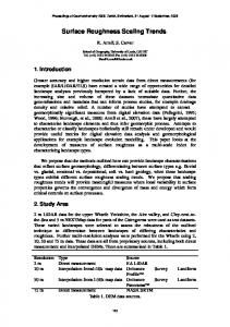
and the final product [5,6]. A number of studies have been reported concerning the effect of cutting parameters on surface topography through experimental efforts. Weule et al. [7] studied the machined surface generated in the micro-cutting of steel. They found that the surface roughness increased at a lower feed rate relative to the cutting edge radius. In addition, the surface quality of the steel workpiece was strongly influenced by the workpiece microstructure and the cutting velocity. In their study, rougher surfaces were produced by tools with larger edge radii. Yuan et al. [8] also studied the effect of the cutting edge radius on the surface roughness of aluminum alloys with diamond tools in turning operations. The cutting edge radii of the cutting tools used in this research were 0.3 µm and 0.6 µm. The results showed that the diamond tool sharpness had a considerable influence on the machined surface integrity. When the cutting speed and feed rate used were 314 m/min and 2.5 µm/rev, results showed that the sharper the cutting edge was (that is the smaller cutting edge radius), the better a smaller surface roughness can be got. Son et al. [9] conducted experiments to investigate the characteristics of micro cutting under various depth-of-cuts from 0.1 to 0.5 µm and a fixed feed speed of 3 mm/s. Results showed that, the smallest surface roughness for Oxygen Free High Conductivity Copper (OFHC) was obtained at 0.1 µm depth of cut due to the generation of continuous chip. While for aluminum machining, continuous chip and the smallest roughness were produced at a minimum cutting thickness of 0.2 µm. The smallest surface roughness for OFHC was generated at the 0.1 µm depth of cut, but it was supposed that this surface was produced not by cutting but by burnishing. Therefore, it was concluded that a continuous chip was generated and the surface quality was the best when cutting at the minimum cutting thickness. Several researchers studied various theoretical bases for analytical models to investigate the effects of cutting parameters on surface topography. Burlacu and Iordan [10] developed a mathematical model to investigate the effects of cutting tool diameter, cutting speed, depth-of-cut, and feed rate on surface roughness by using a multiple regression method. Kiswanto et al. [11] researched the effect of spindle speed, feed rate, and machining time on the surface roughness and burr formation of aluminum alloy during the micro milling operation. Campatelli [12] adopted the response surface method to optimize the process parameters for minimizing power consumption in the milling of carbon steel. Kant and Sangwan [13] used an artificial neural network coupled with a Genetic Algorithm for predictive modelling and optimization of machining parameters to minimize surface roughness. Most of the previous studies on surface integrity [14–20] have assumed that the geometric surface finish was influenced by the cutting speed, feed rate, and cutting edge radius. In addition, the surface roughness is also affected by depth-of-cut, tool wear, tool natural frequency, presence of BUE (built-up-edge), workpiece hardness [21–25], etc. The whole nose of the cutting tool actually participates in the micro-cutting process because the metal removal volume is very small. The influence of the mechanism of cutting tool geometry on the surface roughness in micro-cutting when both the cutting tool edge radius and the tool nose are involved in the cutting process is still not clear. This paper aims to investigate the influence of the mechanism of cutting tool parameters on surface topography based on the analysis of a number of surfaces fabricated through the micro milling process. The cutting tool parameters include the cutting edge radius, the flute number, and the helix angle. A comprehensive theory is established to explain the quantitative relationship between parameters and surface topography. The established methodology model can clarify the importance of cutting tool parameters on preparation of a desired surface. In this paper, four different cutting tool geometries including two flutes with helix angle 15◦ and 30◦ , respectively, three flutes with helix angle 15◦ and 30◦ , respectively, are examined to determine the effects of cutting tool geometry on the surface topography by combining theoretical and experimental analyses. The general framework of this research is shown in Figure 1.
Materials 2017, 10, 120 Materials 2017, 10, 120 Materials 2017, 10, 120
3 of 20 3 of 20 3 of 20
3-Dmodeling modelingofofmicromicro3-D millingtool tool milling
Analysisofofswept sweptmechanisms mechanismsofof Analysis cuttingtool toolon onsurface surfacetopography topography cutting Quantitative Quantitative
Qualitative Qualitative
Experimentalresearch researchon oncutting cutting Experimental tool geometry on surface tool geometry on surface topography topography
Results Results Recreationson onimproving improvingofof Recreations surfaceroughness roughnessand andpreparing preparing surface cuttingtool tool cutting
Proposedmodel model Proposed
Experiments Experiments
Figure 1. Scope of this research. Figure 1. Scope of this research. Figure 1. Scope of this research.
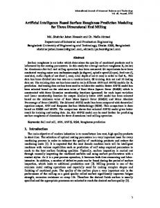
2. Swept Mechanisms of Tool Geometry Effect on Surface Topography 2.2. Swept Mechanisms of Tool Geometry Effect on Surface Topography Swept Mechanisms of Tool Geometry Effect on Surface Topography 2.1. Three Dimensional Geometrical Modeling of Micro‐Milling Tool 2.1. Three Dimensional Geometrical Modeling of Micro-Milling Tool 2.1. Three Dimensional Geometrical Modeling of Micro‐Milling Tool In the micro‐milling process, the actual geometry involved in the process is determined by the In the micro-milling process, the actual geometry involved in the process is determined by In the micro‐milling process, the actual geometry involved in the process is determined by the major cutting edge, the minor cutting edge, and the third edge called the back‐side cutting edge as the major cutting edge, the minor cutting edge, and the third edge called the back-side cutting edge as major cutting edge, the minor cutting edge, and the third edge called the back‐side cutting edge as shown in Figure 2 [26]. All of these three cutting edges should be considered when modeling the shown in Figure 2 [26]. All of these three cutting edges should be considered when modeling the actual shown in Figure 2 [26]. All of these three cutting edges should be considered when modeling the actual geometry of the cutting tool involved in the micro‐machining. geometry of the cutting tool involved in the micro-machining. actual geometry of the cutting tool involved in the micro‐machining.
Majorcutting cuttingedge edge Major AA Back-sidecutting cuttingedge edge Back-side Minorcutting cuttingedge edge Minor
Figure 2. General view of cutting edge of milling cutter. Figure 2. General view of cutting edge of milling cutter. Figure 2. General view of cutting edge of milling cutter.
The mathematic models of the actual geometry of the cutting tool involved in machining can be The mathematic models of the actual geometry of the cutting tool involved in machining can be The mathematic models of the actual geometry of the cutting tool involved in machining can be developed through coordinate translation and transformation [27]. developed through coordinate translation and transformation [27]. developed through coordinate translation and transformation [27]. Three different coordinate systems are used for modeling the description. The CS0 is a global Three different coordinate systems are used for modeling the description. The CS0 is a global Three different coordinate systems are used for modeling the description. The CS0 is a global coordinate system of the cutting tool. Point A existing in the cutting tool tip as shown in Figure 2 is coordinate system of the cutting tool. Point A existing in the cutting tool tip as shown in Figure 2 is coordinate system of the cutting tool. Point A existing in the cutting tool tip as shown in Figure 2 is represented on the coordinate system O‐XYZ as shown shown in 3. Figure 3. The The coordinate coordinate system is is represented on the coordinate system O-XYZ as shown in Figure The coordinate system is established represented on the coordinate system O‐XYZ as in Figure 3. system established with the coordinate origin O at the center of the circular‐arc of the minor‐cutting edge with the coordinate origin O at the center of the circular-arc of the minor-cutting edge [28]. The Z-axis established with the coordinate origin O at the center of the circular‐arc of the minor‐cutting edge is[28]. The Z‐axis is set to be the direction of the minor cutting edge. The X‐axis is set in a direction set to be the direction of the minor cutting edge. The X-axis is set in a direction perpendicular to [28]. The Z‐axis is set to be the direction of the minor cutting edge. The X‐axis is set in a direction perpendicular to the tangent line of the minor cutting edge. The Y‐axis is set perpendicular to the the tangent line of the minor cutting edge. The Y-axis is set perpendicular to the X- and Z-axes. perpendicular to the tangent line of the minor cutting edge. The Y‐axis is set perpendicular to the X‐ and Z‐axes. X‐ and Z‐axes.
Materials 2017, 10, 120 Materials 2017, 10, 120 Materials 2017, 10, 120
4 of 20 4 of 20 4 of 20
CS0 CS0 Figure 3. Minor cutting edge in coordinate system O‐XYZ. Figure 3. Minor cutting edge in coordinate system O-XYZ. Figure 3. Minor cutting edge in coordinate system O‐XYZ.
Then the point A at the minor‐cutting edge can be expressed in Equation (1). Then the point A at the minor‐cutting edge can be expressed in Equation (1). Then the point A at the minor-cutting edge can be expressed in Equation (1).
x R R 1 cos cos x x =1 R1 cos ζ k ,kk=yy R R sin A(,ζ, ζ AA ) y =1 sin R11 sin z= k− kk z z
(1)(1) (1)
is the angle where 0