The SURFNET program generates molecular surfaces and gaps between surfaces ..... In fact, as the illustration shows, only the middle part of the inhibitor is located within ..... 34 Adobe Systems, Inc. PostScript Language Reference. Manual.
r~UTTE RWORTH
SURFNET: A program for visualizing molecular surfaces, cavities, and intermolecular interactions Roman A. Laskowski Biomolecular Structure and Modelling Unit, Department of Biochemistr 3, and Molecular Biology, Universi~' College, London WC1E 6BT, England
The SURFNET program generates molecular surfaces and gaps between surfaces from 3D coordinates supplied in a PDB-format file. The gap regions can correspond to the voids between two or more molecules, or to the internal cavities and surface grooves within a single molecule. The program is particularly useful in clearly delineating the regions of the active site of a protein. It can also generate 3D contour surfaces of the density distributions of any set of 3D data points. All output surfaces can be viewed interactively, along with the molecules or data points in question, using some of the best-known molecular modeling packages. In addition, PostScript output is available, and the generated surfaces can be rendered using various other graphics packages. Keywords: Molecular surfaces, cavities, binding sites, molecular interactions
INTRODUCTION Protein surfaces and internal cavities are of interest for the understanding of many aspects of protein structure and function. The shape and chemical properties of the surface govern interactions with other molecules, such as DNA, 1 ligands, 2'3 and other proteins, 4 and also form the basis of quaternary structure in multimeric proteins. 5 The size and shape of indentations in the surface are particularly important in ligand binding, and hence crucial in structure-based drug design. 6'7 Internal cavities affect protein stability 8 and
Color Plates for this article are on pages 307-308. Address reprint requests to Dr. Laskowski at the Biomolecular Structure and Modelling Unit, Department of Biochemistry and Molecular Biology, University College, Gower Street, London WC1E 6BT, England.
Journal of Molecular Graphics 13:323-330, 1995 © 1995 by Elsevier Science Inc. 655 Avenue of the Americas, New York, NY 10010
play an important role in the close packing of amino acid side chains, particularly in the core of the protein. 9-1~ A number of programs are available for visualizing molecular surfaces and cavities. Molecular surfaces are most usually displayed as dot-surfaces 12 by the commonly used molecular modeling programs, such as 013 and QUANTA (Molecular Simulations, Inc., Burlington, MA). The dots are placed at the van der Waals radius of each atom, at a given density and coloring, and provide an indication of the molecular surface. Where two molecules interact, their dotsurfaces can show their complementarity at the interface. Solid renderings of surfaces can also be generated by these and other packages (Ref. 14 and references therein), with appropriate texturing and reflections. ~5 For large molecules, such as proteins, these representations are difficult to manipulate interactively on the graphics, although graphics packages exist that can do this well, such as AVS (Advanced Visual Systems, Inc., Waltham, MA). One excellent program designed specifically for visualizing molecular surfaces, and in particular their electrostatic potentials, is GRASP, 16 which has quickly become very popular because of the striking images it generates. Various methods and programs exist for visualizing cavities and surface grooves. Both types of region are difficult to perceive from just viewing a molecular surface alone. A given cavity, as defined by the convex surface of the atoms surrounding it, is a concave region that, because the atoms cannot fit together without leaving gaps, branches into myriads of channels and grooves in all directions and is impossible for the mind to grasp. Programs that best depict cavities, therefore, show them as convex surfaces, often built up by fitting probe spheres into the cavities in some manner, and then defining a surface around the resultant collection of interpenetrating spheres. By defining a minimum sphere size, the myriads of small gaps and crevices between the atoms are excluded and only the significant gaps are depicted. Internal cavities, which are completely closed off from the outside world, are relatively easy to detect. The program of Ho and Marshall, ~7 for example, "flood-fills" a cavity
0263-7855/95/$10.00 SSDI 0263-7855(95)00073-9
from a given start point. The VOIDOO program 18 detects cavities, and certain invaginations as well, by an "atomfattening" procedure that progressively closes off small channels both between cavities and also between cavities and the outside world by gradually increasing the atomic radii. The HOLE program of Smart et al. 19 is specifically geared to identifying, measuring, and visualizing ion channels in proteins, stepping through the channel from a given start point and filling it with spheres. Some programs locate internal cavities as a by-product of generating the molecular surface. For example, the GRASP program, mentioned above, locates internal cavities on the basis of the connectivities of the surface elements. Similarly, the algorithm of Voorintholt et al. ,2o which is used by the WHAT IF molecular modeling packing, 21 can show the molecular surface that is accessible to different probe sizes as a density map, and so can detect the internal cavities of the molecule. Surface grooves and indentations, on the other hand, are much more difficult to depict--principally because of the difficulty of knowing how far into open space to extend the groove region; where does the "sea level" of that part of the surface lie? The program of Delaney 22 uses a pattern recognition technique to identify the limits for the floodfilling procedure. The POCKET program 23 is an interactive cavity-filling program that detects pocket regions in the structure by placing a trial sphere of a given radius at points on a three-dimensional (3D) grid. At each grid point the sphere either makes, or does not make, contact with atoms from the molecule. Regions of no contact that are bounded by contact regions in either the x, y, or z directions are deemed to be cavities or pockets. Other cavity-detection algorithms concern themselves primarily with the detection and analysis of cavities rather than with their visualization (e.g., Refs. 24-26). These usually involve moving a probe sphere about the surface to detect completely or partially buried voids. Here we describe a new program, SURFNET, which generates both molecular surfaces and surfaces that delineate cavities, surface grooves, and pockets. The main advantages of the program are that the cavity and pocketdetection algorithm is very fast and simple, and that the program output is not tied to any one molecular graphics program; it can generate density maps for several different packages, namely FRODO, 27 O, QUANTA, and SYBYL (Tripos Associates, Inc., St. Louis, MO). Additionally, each of the surfaces can be output as either PostScript or Raster3D 28'29 files, meaning that they can be imported into various other graphics software packages. Crude measures of the volumes of the molecules and gap regions are also provided in the output. The program has several applications. First, it can depict the internal cavities and surface pockets of large molecules such as proteins. The pockets are particularly useful in molecular modeling and drug design, where the regions of space available for binding ligands are clearly delineated. Second, the gap regions between two or more molecules can be visualized. Thus, for example, one can investigate the specificity of different inhibitors for a given binding site by viewing how closely the surfaces of the two molecules complement one another. Similarly, the interfaces between molecular subunits can be investigated (e.g., helix-helix
324
J. Mol. Graphics, 1995, Vol. 13, October
packing). Here again, the size and shape of the gap regions between the molecules or subunits gives an indication of the closeness of their fit. As a by-product of the surface-generation routines, SURFNET can also be used for contouring 3D density distributions of any general set of 3D data points. Examples of all these applications are presented.
SURFACE G E N E R A T I O N The program generates the following types of surfaces from coordinate data supplied in Protein DataBank (PDB) 3° format: • • • •
van der Waals surfaces Gap regions between two or more molecules Cavities and grooves within a single molecule 3D density distributions of data points
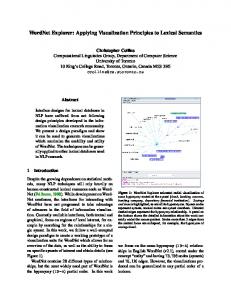
Related programs PLANE, CURVE, and GENBOX can generate surfaces representing planes, paraboloids, cubic surfaces, or boxes. Each surface is output as a 3D grid of density values, using a simple Gaussian function applied to each atom in the input PDB file. This approach is similar to the contouring method of Murray-Rust and Glusker, 3' which employs a spherical atomic electron density function with a characterizable temperature factor. The SURFNET function, depicted in Figure 1, is of the form p = poe
_
kr 2
where p is the density assigned to a given grid point at a distance r from the center of the atom, Po is the density at the center of the atom (i.e., at r = 0), and k is a constant. Only grid points within three times the radius of the atom are updated as the density values become negligible beyond this distance (Figure 1). I
200 180 160140120-
D e n s i t y at
.
10080 60 40 20 0 -8
-6
-4
-2
4
6
8
Distance, r (Angstroms) Figure 1. The Gaussian function used f o r representing the density P o f an atom at a distance r A away. The function shown is f o r an atom with a van der Waals radius, rvaw, o f 2.0 A; the density at r = +-rvaw is 100.0.
The constant k is chosen so that the density at the van der Waals radius of the atom, r = rvdw, is half the central value Po; hence k = (In 2)/r2dw The different van der Waals radii, rvaw, that are used are as follows: Atom
C Fe H N
(Carbon) (Iron) (Hydrogen) (Nitrogen)
Atom
rvd w
1.87 1.10 1.20 1.65
A ,~ ,~ ,~
0 P S X
(Oxygen) (Phosphorus) (Sulfur) (Other)
rvdw
1.40 A 1.90 1.85 1.50 A
To make contouring simpler, the density at the center of each atom, Po, is chosen to be 200.0 and hence the van der Waals surface, being where the density is half this value, is defined by a contour level of 100.0 (Figure 1). Figure 2d shows the density values generated by a single atom on its nearby grid points. When these density values are contoured at a value of 100.0, the surface of the original sphere is regenerated as a set of polygons, as shown in Figure 2e. The smaller the grid spacing the closer the final surface to the original sphere. When generating the surface of a whole molecule, the covalently bonded atoms will have their van der Waals radii overlapping and their surfaces interpenetrating. Thus simply summing their individual density contributions would give a distorted surface wherever these overlaps occur. To counteract this, only the largest density contribution is stored at each grid point. That is, each grid point is assigned the value p from a given atom only if this is larger than the current value of the grid-point. This ensures that the overall surface of the whole molecule is accurately represented by a single contour level of 100.0. As well as generating molecular surfaces, SURFNET can also be used to generate a density distribution from a set of data points (much as in Ref. 31). In this case, the density values are summed together. Another difference is that the value of the parameter Po is empirically determined by the program at each run such that the net contribution of each data point to the total density, when smoothed cross all grid points, is unity. This ensures that the density values in the grid reflect the density of data points everywhere.
DEFINING GAP REGIONS, GAP VOLUMES, AND BINDING SITES One of the most useful applications of the program is in delineating gap regions, as cavities, within a molecule or between two or more molecules. Like the surfaces, the gap regions can be viewed interactively using one of several common molecular modeling packages. The algorithm for detecting gaps is particularly straightforward, and is illustrated in Figure 2. The gap regions are built up simply by fitting spheres into the spaces between atoms. This is similar to the approach of Kuntz et a1.,32 whereby each sphere is generated tangent to surface points
i and j with its center on the surface normal at point i; and in the POCKET program of Levitt and Banaszak, 23 in which spheres are placed on a regular lattice and adjusted in size until they just touch the nearest atom. SURFNET differs in that it considers all relevant pairs of atoms in turn and places a sphere midway between each pair, reducing its size if it clashes with any neighboring atoms. For example, if one is interested in the g a p regions between an enzyme and its inhibitor, each atom of the enzyme is considered in turn with each atom of the inhibitor. For each pair of atoms a trial sphere is placed midway between their surfaces, just touching each one, as shown in Figure 2a. The radius of the sphere is then reduced whenever any neighboring atom is found to penetrate it, until all neighboring atoms have been considered, and one is left with a final gap sphere as shown in Figure 2b. If this sphere is still above some minimum size (usually 1.0 A), its position and radius are stored. The procedure is repeated until all possible pairs of atoms have been considered and one is left with a set of gap spheres filling the region between the molecules (Figure 2c). The surface encompassing these spheres is then generated as described above for van der Waals surfaces. Figure 2d and e illustrates the procedure for a single sphere. The net result is a contour surface (Figure 2f) that delineates the gap regions between the two molecules. When viewed on a graphics terminal, together with the molecules in question, the gap regions clearly show where the molecules are not in contact with one another. Conversely, the absence of gaps shows where the molecules are packing closely against one another. This procedure can be applied to visualizing the internal cavities and surface grooves in a single molecule. Here all pairs of atoms from the one molecule are considered. This gives a natural way of defining the "sea level" of the surface; wherever part of the molecule protrudes out from the surface, the use of all atom pairs to define gaps ensures that any grooves around the protrusion are included. The approach is particularly useful for locating and defining binding sites in proteins. The binding site will usually by the largest of the gap regions, as found for a few examples by Kuntz et al. 32 A program called MASK enables you to pick out the required gap region from all those found by SURFNET. This region, by clearly delineating the binding site, is then a valuable aid in drug design as it shows the space available for docking new ligands or modifying existing ones. In addition, SURFNET provides a crude measure of the volume of each gap region by counting the numbers of grid points within its surface. The volume of any molecular surfaces is computed in the same manner, and hence provides a means of obtaining the volume of the molecule(s) in question. PROGRAM
OUTPUTS
SURFNET outputs its surfaces a density maps in one of several formats: QUANTA (Molecular Simulations, Inc.), SYBYL (Tripos Associates, Inc.), and CCP4 format. 33 The last of these can be used to convert into FRODO 27 and 013 formats.
J. Mol. Graphics, 1995, Vol. 13, October
325
,~,
~--->',
,',~,"
)
,, -_7/,,
'~" (--"" i ~Initialtrial
~
_ gap sphere
,s"
\
,
~,',!Jl )->' ', ;I ~N4S~--
,, .__.-,,,
-f ( ! )Final
', 1",,.4...J gal~sphere Initial', _ i . ,
,, ",,
,,"
gap spheres
,I
d 9.5
25.5
46.1
56.1
46.1
25.5
',...... ,~...... r ..... ] ...... T ...... r .....
9.5
]
~i.o4~L---4-L--~ '~i~i.9'.o .... 5_~o_____~j.~i~ 2!2 516~_
7, 7'
1~._3_ __. 2~,5 ....
4_~:7 _. 6i.6
~.2
15.5
~.6
gap.
1t.8
t - .4~.8 ....
1~.5
t 2.~:6_ _ _ _ _1•.3
~,6
D
f
r r
nl
~
ured
region
~.2
Grid density values
Figure 2. Generation of gap regions between two molecules. Gap regions are defined by first filling the region between the two molecules with "gap spheres" and then computing a 3D surface around them. (a) Each gap sphere is placed between a pair of atoms, as shown for atoms A and B, midway between their van der Waals surfaces and just touching each one. If any neighboring atoms penetrate this gap sphere its radius is reduced until it just touches the intruding atom. If the radius of the sphere falls below some predetermined minimum limit (usually 1.0 A) it is rejected. Otherwise, (b) the final sphere is saved. (c) When all pairs of atoms have been considered the saved gap spheres fill the gap region. (d) Each sphere is used to update points on a 3D grid (a 2D slice of which is shown here), using a Gaussian function as in Figure 1. (e) When contoured, the densities in the array give. a 3D contour surface made of polygons that approximates the original sphere. (f) The contour surface surrounding all the interpenetrating gap spheres in (c) gives a boundary that clearly delineates the size and shape of the gap region.
These surfaces can also be contoured and output in PostScript format 34 and by the related programs SURFACE and SURFPLOT. SURFPLOT can plot the surfaces either a wire-cage diagrams, or as rendered, solid surfaces. In Figures 4b, for example, both representations are included. The program can also produce " b o x plots," like that shown in Figure 5, wherein the objects in the scene are back-projected onto the three walls of a box to give a better idea of their 3D disposition. As well as outputting in PostScript format, SURFPLOT can also output Raster3D-format files, for rendering the surfaces using the program Raster3D. 28'29 It is also possible to import the surfaces into AVS (Advanced Visual Systems, Inc.) for rendering and interactive manipulation.
326
J. Mol. Graphics, 1995, Vol. 13, October
EXAMPLES A number of examples of SURFNET applications are given in Figures 3-5 and Color Plates 1-5 and described below.
Binding sites The first example is shown in Figure 3 and illustrates how SURFNET can be used to delineate the shape of the binding sites of a protein. Figure 3a shows the surface of the aspartic protease endothiapepsin (EC 3.4.23.6) with the inhibitor H-189 in its binding site, held in place by the binding flap. The structure is taken from the PDB entry 3er5. 35 Figure 3b shows the surfaces of all the gap regions generated
_/-~ }.;5-.~)
a
,-. t
/ t\
.
jg'