Surpassing digital holography limits by lensless object scanning holography Vicente Micó,* Carlos Ferreira, and Javier García Departamento de Óptica, Universidad de Valencia, C/ Doctor Moliner 50, 46100 Burjassot, Spain *
[email protected]
Abstract: We present lensless object scanning holography (LOSH) as a fully lensless method, capable of improving image quality in reflective digital Fourier holography, by means of an extremely simplified experimental setup. LOSH is based on the recording and digital postprocessing of a set of digital lensless holograms and results in a synthetic image with improved resolution, field of view (FOV), signal-to-noise ratio (SNR), and depth of field (DOF). The superresolution (SR) effect arises from the generation of a synthetic aperture (SA) based on the linear movement of the inspected object. The same scanning principle enlarges the object FOV. SNR enhancement is achieved by speckle suppression and coherent artifacts averaging due to the coherent addition of the multiple partially overlapping bandpass images. And DOF extension is performed by digital refocusing to different object’s sections. Experimental results showing an impressive image quality improvement are reported for a onedimensional reflective resolution test target. ©2012 Optical Society of America OCIS codes: (090.1995) Digital holography; (090.4220) Multiplex holography; (100.2000) Digital image processing; (100.6640) Superresolution.
References and links 1. 2. 3. 4. 5. 6. 7. 8. 9. 10. 11. 12. 13. 14. 15. 16.
L. P. Yaroslavsky, Digital Holography and Digital Image Processing: Principles, Methods, Algorithms (Kluwer Academic, 2003). U. Schnars and W. P. O. Jüpter, Digital Holography (Springer-Verlag, Heidelberg, 2005). J. W. Goodman, Speckle Phenomena: Theory and Applications (Roberts & Company, 2006). J. W. Goodman and R. W. Lawrence, “Digital image formation from electronically detected holograms,” Appl. Phys. Lett. 11(3), 77–79 (1967). T. Huang, “Digital holography,” Proc. IEEE 59(9), 1335–1346 (1971). F. Le Clerc, M. Gross, and L. Collot, “Synthetic-aperture experiment in the visible with on-axis digital heterodyne holography,” Opt. Lett. 26(20), 1550–1552 (2001). J. H. Massig, “Digital off-axis holography with a synthetic aperture,” Opt. Lett. 27(24), 2179–2181 (2002). P. Almoro, G. Pedrini, and W. Osten, “Aperture synthesis in phase retrieval using a volume-speckle field,” Opt. Lett. 32(7), 733–735 (2007). J. Di, J. Zhao, H. Jiang, P. Zhang, Q. Fan, and W. Sun, “High resolution digital holographic microscopy with a wide field of view based on a synthetic aperture technique and use of linear CCD scanning,” Appl. Opt. 47(30), 5654–5659 (2008). V. Micó, L. Granero, Z. Zalevsky, and J. García, “Superresolved phase-shifting Gabor holography by CCD shift,” J. Opt. A, Pure Appl. Opt. 11(12), 125408 (2009). B. Katz and J. Rosen, “Super-resolution in incoherent optical imaging using synthetic aperture with Fresnel elements,” Opt. Express 18(2), 962–972 (2010). C. Yuan, H. Zhai, and H. Liu, “Angular multiplexing in pulsed digital holography for aperture synthesis,” Opt. Lett. 33(20), 2356–2358 (2008). P. Feng, X. Wen, and R. Lu, “Long-working-distance synthetic aperture Fresnel off-axis digital holography,” Opt. Express 17(7), 5473–5480 (2009). L. Granero, V. Micó, Z. Zalevsky, and J. García, “Synthetic aperture superresolved microscopy in digital lensless Fourier holography by time and angular multiplexing of the object information,” Appl. Opt. 49(5), 845–857 (2010). V. Micó and Z. Zalevsky, “Superresolved digital in-line holographic microscopy for high-resolution lensless biological imaging,” J. Biomed. Opt. 15(4), 046027 (2010). L. Granero, Z. Zalevsky, and V. Micó, “Single-exposure two-dimensional superresolution in digital holography using a vertical cavity surface-emitting laser source array,” Opt. Lett. 36(7), 1149–1151 (2011).
#162534 - $15.00 USD (C) 2012 OSA
Received 3 Feb 2012; revised 9 Mar 2012; accepted 11 Mar 2012; published 9 Apr 2012 23 April 2012 / Vol. 20, No. 9 / OPTICS EXPRESS 9382
17. Y. Kuznetsova, A. Neumann, and S. R. Brueck, “Imaging interferometric microscopy-approaching the linear systems limits of optical resolution,” Opt. Express 15(11), 6651–6663 (2007). 18. V. Micó, Z. Zalevsky, C. Ferreira, and J. García, “Superresolution digital holographic microscopy for threedimensional samples,” Opt. Express 16(23), 19260–19270 (2008). 19. T. R. Hillman, T. Gutzler, S. A. Alexandrov, and D. D. Sampson, “High-resolution, wide-field object reconstruction with synthetic aperture Fourier holographic optical microscopy,” Opt. Express 17(10), 7873–7892 (2009). 20. M. Kim, Y. Choi, C. Fang-Yen, Y. Sung, R. R. Dasari, M. S. Feld, and W. Choi, “High-speed synthetic aperture microscopy for live cell imaging,” Opt. Lett. 36(2), 148–150 (2011). 21. A. Calabuig, V. Micó, J. Garcia, Z. Zalevsky, and C. Ferreira, “Single-exposure super-resolved interferometric microscopy by red-green-blue multiplexing,” Opt. Lett. 36(6), 885–887 (2011). 22. C. Liu, Z. Liu, F. Bo, Y. Wang, and J. Zhu, “Super-resolution digital holographic imaging method,” Appl. Phys. Lett. 81(17), 3143–3145 (2002). 23. M. S. Hezaveh, M. R. Riahi, R. Massudi, and H. Latifi, “Digital holographic scanning of large objects using a rotating optical slab,” Int. J. Imaging Syst. Technol. 16(6), 258–261 (2006). 24. M. Paturzo, F. Merola, S. Grilli, S. De Nicola, A. Finizio, and P. Ferraro, “Super-resolution in digital holography by a two-dimensional dynamic phase grating,” Opt. Express 16(21), 17107–17118 (2008). 25. L. Granero, V. Micó, Z. Zalevsky, and J. García, “Superresolution imaging method using phase-shifting digital lensless Fourier holography,” Opt. Express 17(17), 15008–15022 (2009). 26. M. Paturzo and P. Ferraro, “Correct self-assembling of spatial frequencies in super-resolution synthetic aperture digital holography,” Opt. Lett. 34(23), 3650–3652 (2009). 27. R. Binet, J. Colineau, and J.-C. Lehureau, “Short-range synthetic aperture imaging at 633 nm by digital holography,” Appl. Opt. 41(23), 4775–4782 (2002). 28. Y. Zhang, X. Lu, Y. Luo, L. Zhong, and C. She, “Synthetic aperture holography by movement of object,” Proc. SPIE 5636, 581–588 (2005). 29. C. Ventalon and J. Mertz, “Quasi-confocal fluorescence sectioning with dynamic speckle illumination,” Opt. Lett. 30(24), 3350–3352 (2005). 30. J. García, Z. Zalevsky, and D. Fixler, “Synthetic aperture superresolution by speckle pattern projection,” Opt. Express 13(16), 6073–6078 (2005). 31. P. Almoro, G. Pedrini, and W. Osten, “Complete wavefront reconstruction using sequential intensity measurements of a volume speckle field,” Appl. Opt. 45(34), 8596–8605 (2006). 32. A. Anand, V. K. Chhaniwal, P. Almoro, G. Pedrini, and W. Osten, “Shape and deformation measurements of 3D objects using volume speckle field and phase retrieval,” Opt. Lett. 34(10), 1522–1524 (2009). 33. P. F. Almoro and S. G. Hanson, “Wavefront sensing using speckles with fringe compensation,” Opt. Express 16(11), 7608–7618 (2008). 34. F. Dubois, L. Joannes, and J.-C. Legros, “Improved three-dimensional imaging with a digital holography microscope with a source of partial spatial coherence,” Appl. Opt. 38(34), 7085–7094 (1999). 35. J. Maycock, B. M. Hennelly, J. B. McDonald, Y. Frauel, A. Castro, B. Javidi, and T. J. Naughton, “Reduction of speckle in digital holography by discrete Fourier filtering,” J. Opt. Soc. Am. A 24(6), 1617–1622 (2007). 36. T. Nomura, M. Okamura, E. Nitanai, and T. Numata, “Image quality improvement of digital holography by superposition of reconstructed images obtained by multiple wavelengths,” Appl. Opt. 47(19), D38–D43 (2008). 37. L. Rong, W. Xiao, F. Pan, S. Liu, and R. Li, “Speckle noise reduction in digital holography by use of multiple polarization holograms,” Chin. Opt. Lett. 8(7), 653–655 (2010). 38. F. Pan, W. Xiao, S. Liu, F. J. Wang, L. Rong, and R. Li, “Coherent noise reduction in digital holographic phase contrast microscopy by slightly shifting object,” Opt. Express 19(5), 3862–3869 (2011). 39. Y. K. Park, W. Choi, Z. Yaqoob, R. Dasari, K. Badizadegan, and M. S. Feld, “Speckle-field digital holographic microscopy,” Opt. Express 17(15), 12285–12292 (2009). 40. J. Goodman, Introduction to Fourier Optics, 2nd ed. (McGraw-Hill, New York, 1996). 41. M. Born and E. Wolf, Principles of Optics, 7th (expanded) ed. (Cambridge University Press, 1999). 42. T. Colomb, J. Kühn, F. Charrière, C. Depeursinge, P. Marquet, and N. Aspert, “Total aberrations compensation in digital holographic microscopy with a reference conjugated hologram,” Opt. Express 14(10), 4300–4306 (2006).
1. Introduction Digital holography (DH) arises from the same holographic principles than classical holography but replacing the holographic plate recording media by a solid state image recording device (typically a CCD or CMOS camera) composed by a matrix of light sensitive elements [1,2]. DH has the great advantage derived from the flexibility and the versatility of the numerical reconstruction provided by computers. However, DH suffers from the drawbacks inherent to electronic devices, maintaining the characteristics of using coherent illumination. The use of digital cameras addresses with a limitation of both spatial resolution and field of view (FOV) of the reconstructed image due to the limited number of pixels and the pixel size of the electronic imaging device. In addition, the use of coherent illumination generates noise (mainly due to speckle and coherent artifacts) which also degrades the spatial
#162534 - $15.00 USD (C) 2012 OSA
Received 3 Feb 2012; revised 9 Mar 2012; accepted 11 Mar 2012; published 9 Apr 2012 23 April 2012 / Vol. 20, No. 9 / OPTICS EXPRESS 9383
resolution, the signal-to-noise ratio (SNR) and phase accuracy of the reconstructed images [3]. For those reasons, many attempts have been made to overcome those drawbacks since the first implementations of DH [4,5]. As for the FOV limitation, scanning a larger hologram using the matrix detector is the most used approach for improving performance in DH. By scanning we mean a relative motion between the object and the digital camera and it implies the generation of an expanded hologram containing a bigger portion of the diffracted object wavefront, bigger in comparison with the non-scanning case. The generation of that expanded hologram is commonly known as aperture synthesis and can be implemented using, in essence, 4 different strategies [6–28]. The first one deals with the displacement of the camera at the recording plane [6–11] thus synthesizing a larger hologram in comparison with that one provided by only one camera position. The second performs synthetic aperture (SA) generation by angular multiplexing the spectral object information [12–16]. Angular multiplexing is implemented by tilted beam illumination over the object in a similar way than in digital holographic microscopy [17–21] and allows the recovery of additional spatial frequencies falling outside the digital camera sensible area when on-axis illumination is used. The third option is related with the use of additional optical elements (typically diffraction gratings) that are placed between the object and the digital camera [22–26]. The diffraction grating directs towards the camera an additional portion of the diffracted object wavefront allowing the generation of the synthetic aperture hologram. And finally, the fourth case is based on object movement instead of shifting the digital camera [27,28]. On the other hand, speckle has been validated as a usable tool for, for instance, depth discrimination [29], superresolution (SR) [30], phase retrieval [31], shape measurement [32], and wavefront sensing [33]. However, in other applications speckle is an unwanted feature to be reduced in order to improve image quality. Thus, coherent noise reduction in DH have been attained by using partial spatial coherence sources [34], with implementations based on digital image processing [35], by approaches based on the averaging of multiple holograms recorded with different wavelengths [36] or with polarization states [37], or by slightly shifting the sample [38] or by changing the phase of the illumination [39] between them, just to cite a few. In addition, aperture synthesis [7,8,13,20,27] has also been validated as a useful strategy for reducing both size and contrast of the speckle noise as a consequence of both SA enlargement and overlapping between elementary apertures when generating the SA, respectively. Among the previous reported methods to achieve SA generation in DH [6–28], approaches based on the object movement [27,28] are by far the less exploited ones. In fact, only rotation has been considered until now. In this report, we propose the use of object translation to synthesize a final digital image with improved capabilities concerning resolution, FOV, SNR and DOF in reflective DH. The proposed method, named as Lensless Object Scanning Holography (LOSH), profits of the linear movement of the object to record a set of reflective digital lensless Fourier holograms containing different spatial as well as spatial frequency information of the scanned object. Different spatial information comes from a different object region being recovered for each hologram due to the linear object displacement. Different spatial frequency content accounts for a given object area being illuminated under different angular directions depending on its position along the scanned direction and assuming that the illumination beam is enough divergent. Those two characteristics produce object FOV enlargement and resolution improvement, respectively, when considering the whole set of recorded holograms. Moreover, if the object displacement between contiguous holograms is small in comparison with the retrieved FOV for a single hologram, the SNR of the final image is also enhanced due to the averaging of the coherent noise when adding the whole set of recorded holograms. As a result, the final image provided by LOSH resembles an image obtained under white light illumination but considering that not only intensity but also phase information is accessible. Thus, an extended DOF image can be also synthesized owing to the coherent nature of LOSH by numerical propagation to different axial distances.
#162534 - $15.00 USD (C) 2012 OSA
Received 3 Feb 2012; revised 9 Mar 2012; accepted 11 Mar 2012; published 9 Apr 2012 23 April 2012 / Vol. 20, No. 9 / OPTICS EXPRESS 9384
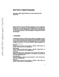
The paper is organized as follows. Section 2 theoretically presents the experimental layout as well as a description of the numerical processing involving LOSH. Experimental results are reported in Section 3 for reflective objects concerning FOV enlargement, resolution and SNR enhancement, and DOF extension. And finally, Section 4 concludes the paper. 2. Theoretical analysis 2.1 System description The experimental setup of the LOSH is depicted in Fig. 1. It is a classical lensless Fourier holographic configuration implemented in a Michelson-Morley interferometer. In the imaging branch, a divergent spherical point source illuminates the input object after reflecting in a non-polarizing beam splitter cube (BS). The back-diffracted wavefront reaches the hologram plane at the CCD. The light transmitted by the BS is reflected back by a reference mirror arriving at the CCD. This reference beam has the form of a spherical beam diverging from at the same distance as a virtual point source generated by the image of the real point source at the reference mirror. If the input object is placed just at the same distance from the CCD (D in Fig. 1(b)) but in the imaging branch, the recorded hologram becomes in a digital lensless Fourier hologram where the input object is imaged at one of the diffraction orders of the recorded hologram. In order to maximize the resolution of experimental layout, the reference mirror is glued to the BS using matching index immersion oil. This configuration is maintained for every input object position when considering the object displacement.
Fig. 1. Upper view of the proposed LOSH layout: (a) ray tracing for imaging and reference beams, and (b) identification of the main parameters for the mathematical analysis.
2.2 Mathematical analysis Let us characterize the amplitude distribution of the reflective input object by O(x1, y1). This object is illuminated by a spherical divergent wave Aexp[jk(x12 + y12)/(2D0)] coming from the point source that is initially located at an effective distance D0. This effective distance takes into account the passing of the spherical wave through the higher index medium of the BS. This is not troublesome since it affects equally to both interferometric branches. According to the geometry of Fig. 1, the point source is placed at a distance d1 from the upper face of the BS and the CCD detector at a distance d2 from the right face. Then, d1 is related with the position of the object through the definition of the virtual point source plane in order to assure the holographic recording in a lensless Fourier configuration. And d2 is, in principle, arbitrary but it determines the region of the input object that can be fully recovered in the reconstruction process (region that we will name as FOV). For the sake of simplicity in the mathematical analysis, let us suppose that d1 = d2. In this particular case, the object is placed at half the distance between the illuminating point source and the CCD. Moreover the distance D between the object and the CCD becomes equal to D0. Thus, just after reflection on the input object, except for constant amplitude factors, the field distribution provided by the imaging arm is
#162534 - $15.00 USD (C) 2012 OSA
Received 3 Feb 2012; revised 9 Mar 2012; accepted 11 Mar 2012; published 9 Apr 2012 23 April 2012 / Vol. 20, No. 9 / OPTICS EXPRESS 9385
k U x1 , y1 exp j x12 y12 O( x1 , y1 ). 2D
(1)
Applying Fresnel diffraction and dropping the irrelevant linear phase factor, the field distribution at the plane (x2, y2) where the CCD is located can be written as
1 k k exp j x 22 y22 U x1 , y1 exp j x12 y12 j D 2D 2D (2) 2 k 2 2 exp j x y2 F u , v x1 x2 y1 y2 dx1dy1 C exp j D 2D 2
U x2 , y2
where
k F u, v U x1 , y1 exp j x12 y12 exp j 2 ux1 vy1 dx1dy1 2D k FT U x1 , y1 exp j x12 y12 2 D
(3)
the spatial frequencies being (u, v) = (x2/(λD), y2/(λD)) and C = 1/(jλD). Complex amplitude distribution of Eq. (2) interferes with the reference beam generated at a virtual point source located at the same distance D in front of the CCD. If, moreover, the reference mirror is slightly tilted, the reference virtual point source becomes shifted a distance b outside the optical axis. In our case, this shift is achieved by tilting both the BS and the reference mirror in the direction that is perpendicular to the object scanning direction. Assuming that the object is moved along the x-direction, b is perpendicular to Fig. 1 (ydirection). For instance, when b