Survey on Benchmarks for a GPU Based Multi Camera Stereo Matching Algorithm Klaus Denker1 and Georg Umlauf1 1
Computer Graphics Lab, Department of Computer Science University of Applied Sciences Konstanz Brauneggerstr. 55, 78462 Konstanz, Germany kdenker,
[email protected]
Abstract Stereo matching algorithms and multi camera reconstruction algorithms are usually compared using benchmarks. These benchmarks compare the quality of the resulting depth map or reconstructed surface mesh. We describe the differences between several known stereo and multi-view stereo benchmarks and their various datasets. Also the modifications that are necessary to use our own GPU based multi camera stereo matching algorithm with the data from these benchmarks are discussed. Keywords and phrases Stereo matching, Multi camera, GPU Digital Object Identifier 10.4230/OASIcs.VLUDS.2010.20
1
Introduction
Stereo matching is a technique to compute from two or more 2D camera images a depth map of the captured object. It is used in many applications ranging from remote sensing to robotics, archeology, cultural heritage, reverse engineering, and 3D face recognition [3, 6, 7, 15]. Its appeal comes from the fact that it is the only passive method to generate depth information. This means only natural light is used for the data acquisition and there is no interaction with the object that might harm the object. Benchmarks in this field allow the comparison of the quality of stereo matching algorithms. As the applications of stereo matching algorithms differ, there are multiple benchmarks using diverse test datasets. They range from 2 to 363 images, taken from parallel, spherical, or arbitrary camera positions. They also use different result representations, depth maps or meshes, and different comparison methods [8, 11, 13]. Our GPU based multi camera matching [1] is tailored for fast face recognition. It does not fit well to any of the intended benchmark scenarios. This either causes bad results or adaptations of the algorithm to process the benchmark datasets and result data. We describe the benchmarks in Section 2, our matching algorithm in Section 3, and the application to the benchmarks in Sections 4 and 5.
2 2.1
Benchmark survey Middlebury stereo benchmark
One method to compare the quality of stereo matching algorithms is presented in [8]. Several pairs of photographs of carefully constructed test scenes are used. All stereo matching algorithms are compared to hand-labeled ground truth disparity maps. The test photographs have a low resolution of 384 × 288 or 435 × 383 pixels. Each image pair differs only by a small horizontal displacement of the camera. The viewing directions © Klaus Denker and Georg Umlauf; licensed under Creative Commons License NC-ND Visualization of Large and Unstructured Data Sets– IRTG Workshop, 2010. Editors: Ariane Middel, Inga Scheler, Hans Hagen; pp. 20–26 OpenAccess Series in Informatics Schloss Dagstuhl – Leibniz-Zentrum für Informatik, Dagstuhl Publishing, Germany
Klaus Denker and Georg Umlauf
21
of both images are exactly parallel. In the used test scenes most objects have flat surfaces parallel to the image planes of the cameras. This flat structure of the whole scene is necessary to create the ground truth disparity maps. They are build by hand-labeling the contours of all flat regions and computing an alignment for the whole region. In the disparity map the whole region is marked with the disparity of this alignment. Example images and the corresponding disparity map are shown in Figure 3. Tested stereo matching algorithms have to provide a disparity map. This disparity map is compared with the ground truth disparity map based on the root mean square error. Additionally, the percentage of bad pixels with an error above a threshold is computed. Theses scores are computed for the whole image as well as for certain interesting regions. These regions are texture-less, occluded, and have depth discontinuities. For algorithms using more than two images a set of extended datasets was generated using the method described in [9]. The extended datasets contain up to nine high resolution photographs (1800 × 1500 pixels) of constructed test scenes. As for the stereo pairs, the camera is moved horizontally and all viewing directions are parallel. The ground truth is recorded using a structured light approach. A projector projects multiple Gray-code stripe patterns on the scene. The photographs of these patterns are used to compute the exact disparity of each pixel in two reference images. The official benchmark on the website [10] contains two sets from [8] and two reduced sets from [9]. The reduced sets consist of two images and two ground truth disparity images. Their resolution is reduced to 450 × 375 pixels.
2.2
Dense multi view stereo test images
The benchmark approach of [13] uses multiple photographs from quite arbitrary camera positions. Outdoor scenes with historic buildings are used as test datasets. Different image sets on the benchmark website contain between 6 and 30 images of the facades of different historic buildings. All pictures are taken using a digital camera without any special positioning device. A laser scanner generated the ground truth geometric data. Two example images and the corresponding depth map are shown in Figure 1 (left). Reconstruction of the internal and external camera parameters is part of the benchmark. Thus, this benchmark can be used without camera parameters, with the internal camera parameters, or with all camera parameters. The ground truth camera parameters are reconstructed from feature markers in the scene using a maximum likelihood estimation. Tested algorithms provide a depth map for each photograph. This depth map is compared to a reference depth map created from the laser scan using the ground truth camera parameters. An error value is computed by dividing each pixel’s absolute difference by the local variance of the ground truth laser scan depth map. The benchmark results are presented as a histogram of the different error sizes on the website [12].
2.3
Middlebury multi view benchmark
The Middlebury multi view stereo benchmark described in [11] uses much more data. Pictures from 790 positions on a half-sphere are taken using the Stanford spherical gantry [4]. The spherical gantry uses two computer-controlled arms, one carries a camera, the other a light source. An object is placed in the center between the arms on a turn table. The spherical gantry has a precision of 0.01◦ and the captured images have a resolution of 640 × 480 pixels. A ground truth mesh G is created from multiple laser scans that are merged using a 3D grid.
VLUDS’10
22
Survey on Benchmarks for a GPU Based Multi Camera Stereo Matching Algorithm
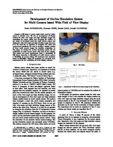
Figure 1 Dataset from Dense multi view stereo testimages (left) [13]. Hemisphere of camera positions, photograph, and result mesh from Middlebury multi view benchmark (right) [11].
Three different datasets of each object can be used for benchmarking. The full datasets contains a hemisphere of 317 to 363 images without shadows of the arms, see Figure 1 (right). Subsets of these datasets are the ring datasets that contain only one ring of 47 to 48 images around the object. The Further reduced sparse ring datasets contain 16 images on the same ring equally distributed around the object. Each algorithm using this benchmark has to provide a mesh reconstruction R of the object. The benchmark measures the nearest distance between each point of R to G and of each point of G to R. The latter is only used to evaluate the completeness of R.
3 3.1
Our multi camera stereo matching The camera system
For our system we use four USB Logitech® cameras QuickCam® Pro 9000. These cameras run at a resolution of 960 × 720 at five frames per second, because they are connected via two USB 2.0 Controllers. The USB-bandwidth limits the camera resolution, which could yield a much higher resolution. To get the best results we use a Y-constellation of the four cameras as shown in Figure 2a. This arrangement has two advantages over e.g. linear configurations. First, the image of the central camera is used as reference image for matching and texturing. Second, we get a different angle between each camera pair. A camera constellation with a preferred direction could deteriorate the detection of features along this direction, e.g. horizontal stripes in the image cause problems in a horizontal camera constellation. Independently of the used hardware system, our method can be adapted to arbitrary camera constellations. This adaption is easier for camera systems where all cameras are mounted on a plane with a viewing direction perpendicular to this plane. For details see [1].
Klaus Denker and Georg Umlauf
3.2
23
Matching
Stereo matching is an operation to find similar regions in two images. We call these square regions matching windows. To find the best matching position for these matching windows they will be moved over the images. Thus, the fundamental operation of stereo matching is the comparison of matching windows of the same size. To this end, each matching window position gets a score that evaluates the similarity of two matching windows. We use a weighted normalized cross-correlation similar to [5]. To get the depth information, the disparity between the images is estimated. For this the matching windows are moved simultaneously over all images to compute the total score of each position. So, the highest total score yields the best position of the matching windows. To evaluate all possible camera positions is too expansive. Thus, the centers of the matching windows are moved only along epipolar lines with respect to the center point of the fixed matching window of the reference image, see Figure 2b.
(a) For our experiments we use a system of four USB cameras arranged in an upside down Y-constellation.
(b) Moving the matching windows (black squares) in all images (gray squares) along epipolar lines (arrows) simultaneously.
Figure 2 The camera configuration and simultaneous movement of the matching windows.
The step size for the movements is one pixel and per matching window in the reference image we test 3 ≤ k ≤ 9 different positions. Due to the movement along the epipolar lines the color values for the score computations are bi-linearly interpolated. The matching window position with the highest score sbest then yields the best similarity of the matching windows. The number of movements gives the disparity dbest of the best match. From the disparity and the camera positions the depth is computed by reverse projection. The process described so far gives the disparity information for one image at a fixed resolution. For large disparities this is computationally expensive, because many possible matching window positions must be evaluated. A multi-level approach can reduce this effort and allows for large disparities. Our approach is based on [16], where a matching pyramid with coupled levels is used. In our approach the different levels are completely independent and high level information is re-used to get a faster low level disparity computation. The camera image is stored in a mip-map on the GPU at seven different resolutions. Each resolution has half the horizontal and vertical resolution of the one before. The matching windows have a fixed size of e.g. 7 × 7 pixels. Starting with the image on the coarsest resolution level the disparities of all pixels in the coarsest reference image are computed. The matching windows are tested at k = 9 different positions. Then the image resolution is doubled and the same process starts again, while k is reduced linearly. The bi-linearly
VLUDS’10
24
Survey on Benchmarks for a GPU Based Multi Camera Stereo Matching Algorithm
interpolated disparities of the coarser level is used as starting position for the lower level matching windows. Thus, the low level matching windows move a fixed number of pixels around the best position of the previous level.
3.3
GPU implementation
Because our method mainly works on images and generates a depth map as an image, we use GLSL fragment shaders for our implementation. Fragment shaders are small programs, running highly parallel on the GPU, processing one or multiple texture images into one result image. For the complex shader operations required by our approach GPUs which support at least shader model 4.0 are necessary. Older GPUs are not able to perform enough computations in a single shader run. The quite complex computations during stereo matching require the combination of multiple shader runs. Each step in our multi-level matching requires the run of three fragment shader programs. Two of them pre-calculate the average and auto-correlation data for the normalized cross-correlation. The third shader performs all matching operations, i.e. it moves the deformed matching windows, computes the total score, and finds the best score.
4 4.1
Results Middlebury stereo benchmark
Our multi camera stereo matching algorithm is tailored for a four camera system. But it can be configured to any other planar camera configuration, where the viewing directions of all cameras are parallel. The standard image set of the Middlebury benchmark Tsukuba consists of two images with small disparities. Our algorithm is optimized for much larger disparities. Therefore, the resulting depth map in Figure 3 is quite inaccurate, especially in the background regions.
Figure 3 The Tsukuba dataset from the Middlebury stereo benchmark [10]. The two source images, reference disparity map, and our resulting depth map.
Much better results are possible using the extended dataset of the same scene. As described in Section 2.1 this dataset consists of five high resolution images. We scale these images to the resolution of our camera system of 960 × 720 pixels. Figure 4 shows a depth map generated from this image set. The quality is much better than in the previous example, only by using more pictures with better resolution for our simultaneous matching.
Klaus Denker and Georg Umlauf
25
Figure 4 The extended Tsukuba dataset from the Middlebury stereo benchmark [10]. The five source images, reference depth map, our resulting depth map, and a 3D rendering of the result.
5 5.1
Necessary modifications Dense multi view stereo test images
The camera positions of the pictures in the benchmark sets of [13] are quite arbitrary. They are not planar and the viewing directions are not parallel. Many of the simplifications of our matching shaders are not possible for arbitrary camera positions and viewing directions. Additional projection and re-projection calculations are necessary. This would affect the calculation speed and increase the complexity of the used GPU shaders. Our multi camera stereo matching shaders support up to five images. The shaders can be modified to support larger image counts as long as the GPU has enough memory. At least the smaller image sets of this benchmark, that contain up to eleven pictures, can be used in a single matching step. Merging operations for multiple depth maps are not necessary.
5.2
Middlebury multi view benchmark
The Middlebury multi view benchmark uses a large number of camera images. Here, it is not possible to do simultaneous depth map calculation. So, a method to combine multiple depth maps and generate a high quality mesh of the object must be developed. To use our algorithms subsets of the camera positions need to be chosen to generate multiple local depth maps. A cross-shaped set of five cameras with one in the center seems ideal. If these cameras are relatively close, this subset is almost planar and has almost parallel viewing directions. This yields a relatively small disparity between the cameras of a local subset, reducing the quality of the matching and complicating the merging of the depth maps. By choosing images that are far away from the center image, this can be improved. Thus, there is the trade-off between parallelism of the viewing directions and the magnitude of the disparities. This approach generates a lot of depth maps from around the captured hemisphere of viewpoints. All of these depth maps have to be merged and converted to a single object mesh. Common methods for this problem use a volume or point cloud representation of the object and do a mesh reconstruction [2, 14]. All these methods have in common, that they are very slow compared to our fast multi camera stereo matching, and are not applicable to
VLUDS’10
26
Survey on Benchmarks for a GPU Based Multi Camera Stereo Matching Algorithm
our application setting.
Acknowledgements This work was supported by DFG GK 1131 and AiF ZIM Project KF 2372101SS9. References 1 2 3 4 5 6 7
8 9 10 11
12 13
14 15
16
K. Denker and G. Umlauf. Accurate real-time multi-camera stereo-matching on the gpu for 3d reconstruction. Accepted: Journal of WSCG, 2011. Y. Furukawa and J. Ponce. Accurate, dense, and robust multi-view stereopsis. In Proceedings of IEEE CVPR 2007, pages 1–8, 2007. R. Koch, M. Pollefeys, and L. Van Gool. Realistic 3-d scene modeling from uncalibrated image sequences. In ICIP’99, Kobe: Japan, pages 500–504, 1999. M. Levoy. The stanford spherical gantry. http://graphics.stanford.edu/projects/gantry/, 2002. J. P. Lewis. Fast template matching. In Vision Interface, pages 120–123, 1995. D. Murray and J. Little. Using real-time stereo vision for mobile robot navigation. In Autonomous Robots, pages 161–171, 2000. D.T. Pham and L.C. Hieu. Reverse engineering - hardware and software. In V. Raja and K.J. Fernandes, editors, Reverse Engineering - An Industrial Perspective, pages 33–30. Springer, 2008. D. Scharstein and R. Szeliski. A taxonomy and evaluation of dense two-frame stereo correspondence algorithms. Int. J. Comput. Vision, 47(1-3):7–42, 2002. D. Scharstein and R. Szeliski. High-accuracy stereo depth maps using structured light. In Proceedings of IEEE CVPR 2003, pages 195–202, 2003. D. Scharstein and R. Szeliski. Middlebury stereo vision page. http://vision.middlebury.edu/stereo/, 2007. S.M. Seitz, B. Curless, J. Diebel, D. Scharstein, and R. Szeliski. A comparison and evaluation of multi-view stereo reconstruction algorithms. In Proceedings of IEEE CVPR 2006, pages 519–528, 2006. C. Strecha. Multi-view stereo test images. http://cvlab.epfl.ch/~strecha/multiview/, 2008. C. Strecha, W. von Hansen, L. Van Gool, P. Fua, and U. Thoennessen. On benchmarking camera calibration and multi-view stereo for high resolution imagery. In Proceedings of IEEE CVPR 2008, pages 1–8, 2008. G. Vogiatzis, P. H. S. Torr, and R. Cipolla. Multi-view stereo via volumetric graph-cuts. In Proceedings of IEEE CVPR 2005, pages 391–398, 2005. F. Voltolini, S. El-Hakim, F. Remondino, and L. Gonzo. Effective high resolution 3d geometric reconstruction of heritage and archaeological sites from images. In Proceedings of the 35th CAA Conference, pages 43–50, 2007. R. Yang and M. Pollefeys. A versatile stereo implementation on commodity graphics hardware. Real-Time Imaging, 11(1):7–18, 2005.