Swing up and Stabilization Control Experiments for a Rotary Inverted Pendulum- An Educational Comparison
Necdet Sinan Ozbek
Mehmet Onder Efe
Department of Electrical and Electronics Engineering TOBB University of Economics and Technology Ankara, Turkey
[email protected] Abstract-
Department of Electrical and Electronic Engineering TOBB Univer sity of Economics and Technology Ankara, Turkey onder ef e@ etu.edu.tr
and
makes the application of the scheme a tedious task [1]. This paper
stabilization control of a rotary inverted pendulum system with
presents the results obtained with linear quadratic controller. Since
This
paper
focuses
on
the
swing
up
linear quadratic regulator (LQR), sliding mode control (SMC)
the optimization problem can be expressed in terms of the tracking
and fuzzy logic control (FLC). The inverted pendulum, a popular
errors and the cost functional, it is possible to develop a linear
control
quadratic controller based on the linearized model of the plant
application
exists in
several
forms and due
to
its
widespread use for prototyping control schemes we present
around the desired operating
experimental
the
applicability of the scheme, the fact that it necessitates the
and
linearized plant dynamics is a drawback making the controller
results
pendulum.
The
introduces
the
obtained
paper
on
develops
implementation
a the
of
rotary
version
dynamical
the
of
model
considered
schemes
point. Despite
the
widespread
useless for he operating points that are dissimilar to the one used for linearization. Sliding mode control, a nonlinear and two sided
comparatively.
witching
type
control
scheme,
is
implemented
to
see
the
robustness and invariance properties. Lastly, the experiments are
Keywords-Rotary inverted pendulum, LQR, fuzzy logic, sliding mode control
I.
carried out to discover the performance of the fuzzy controllers based on sets labeled by linguistic qualifiers and with unsharp boundaries. Each scheme has pros and cons discussed in the paper. So far, many approaches have been proposed to swing up and
INTRODUCTION
The inverted pendulum systems have two typical forms studies frequently in the literature. First is the classical one running on straight path to balance the pole yet the other is the rotary one which is capable of performing swing up. Both are underactuated mechanical systems and they have been studied numerously to demonstrate when a novel scheme is proposed or when a control teaching material is proposed. The nonlinear and coupled nature of the differential equations describing the system dynamics is found further appealing to those experimenting control laws in real time.
stabilization control for inverted pendulum systems. In [2-3], a swing up control algorithm is proposed and in [4], minimum time swing up by iterative impulsive control method is elaborated. Another technique, called energy based control, is studied in [5-6]. The LQR is presented to optimize the controller gains in [7], artificial neural networks and fuzzy logic systems are utilized for swing up process and stabilization in [8-10]. In [11], fuzzy swing up and fuzzy stabilization based on linear quadratic regulator approach
for
the
rotary
inverted
pendulum
is
investigated.
Conventional sliding mode control technique can not be applied
Underactuated systems have fewer actuators than the degrees of freedom. Because of this, the strategies developed for fully actuated systems may not be applied directly to underactuated systems During the last few decades, developing different control strategies for underactuated systems has drawn a great interest as most physical systems have an underactuated description, such as those in robotics, aerospace engineering, and marine engineering. Until recently, designing global controllers for underactuated systems was a challenge, yet, to overcome this problem, the control engineering framework now offers several tools based on quadratic optimization, hard boundary switching laws (sliding
for underactuated systems since they can not be decoupled and not every subsystem is equipped with an individual control channel. In [12], to overcome this problem, a modification to sliding surface is considered. A coupled sliding surface is highlighted for actuated and unactuated states and their time derivatives in [13]. Also an aggressive swing up by saturation functions and a state dependent coupling parameter in coupled sliding surfaces is introduced in [13-14].
Due
to
insufficiency
of
conventional
methods
a
nonregular backstepping technique is proposed in [15]. Sliding mode control, designed by the use of fuzzy sliding surfaces, is introduced in [16-17].
mode control) or soft boundary laws based on fuzzy set theory.
This paper is organized as follows. The second section
Aside from the underactuated nature of the dynamics, the difficulty of the control problem is the desire of balancing the pole around the unstable equilibrium point. Despite the dynamics is well known and it is possible to apply the feedback linearization scheme, the fact that the system is a nonminimum phase one
presents description of the rotary inverted pendulum system and derivation of the mathematical model. LQR and state feedback controller, SMC and FLC are described in the following sections, respectively, with real time experimental results. Finally, the concluding remarks are given at the end of the paper.
978-1-4244-6588-0/10/$25.00 ©2010 IEEE
2226
II. A.
ROTARY INVERTED PENDULUM SYSTEM
Description of the system
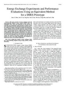
Rotary inverted pendulum system as known Furuta pendulum was fITst developed by Katsuhisa Furuta in Tokyo Institute of Technology. The testing apparatus showing the definitions of the angles are is depicted in Fig. I.
cii-bcos(a)e- dsin(a)=0
where
The system consists of a servo system and a pendulum attached to the tip of a link appropriately as shown above. Angular displacement in the horizontal plane is denoted by 8 and a. denotes angular displacement of the pendulum in the vertical plane (See Fig. 1). The motivation of the problem is to design a controller that swings the pendulum up and balance it at the upright position which is the unstable equilibrium point of the system. Mathematical model of the system is obtained by using Euler Lagrange formulation. As a first step to obtain the dynamic equations of the system: the potential and kinetic energy is given in (1) and (2), respectively.
=
mg/cos(a)
(1)
., . 1 , 1 -J lr +-m.(rB - Lcos(a).(a))" + " 2 2
(2)
1 . . ' 1 .' -m(-Lsma.(a))" +-J a" 2 2 =
Lagrange equation is described by (3). L=T-V
The output torque of the motor is given by (4) Toutput =
17m17gKtKg{Vm -KgKm8) Rm
(3) (4)
where f/m is motor efficiency, fig is gear efficiency of the pendulum and motor arm, Kf motor torque constant, Km electromotor constant, Rm armature resistance and Vm is the input voltage. Euler equations to derive the dynamics are given in (5) and the dynamics of the system is described in (6).
( ) ( )
� 0L o t 00 � oL ot od
_
_
0L = T o u tp u t 08 0L 0
o
a
=
_
B
eq
0
c
=
4mL2
(17m17gKtKmK
;
+
,
d
=
mgL ,
BeqRm) / Rm
PARAMETERS OF THE SYSTEM Value
Unit
0.215
m
0.1675
Length to pendulum's center of mass arm
/3
Jea
Rotating
Rm
Be