be bringing business community and residential customers ... bandwidth transparent (support any bit rate) . The alternative ... H. Scott Hinton AT&T Bell Laboratories channels, while ..... Center, Customer Service Department, 445. Hoes Lane ...
Switchingto photonics mice, video, and data will eventually be switched by hardware that exploits the interplay of photons and electrons elecommunications in the future will rely on light as heavily in switching as it does today on light in transmission. The vast information-carryingcapacity of optical fiber will be joined to the astounding connectivity of photonics. Each new wave of switchinghardware will have more photonics embedded in it. In 1995, the first specialized applications will be appearing. By 2000 there may not be purely photonic switchmg but there certainly will be-abundant photonics; for example, photonic links will interconnect printed-circuit boards, multichip modules, and equipment frames. By 2010, optoelectronic switching fabrics could be bringing business community and residential customers alike a panoply of broadband services: video, highdefinition television, and switched videotelephone conversations and conferences; fast data file transfers and information retrieval; data exchange for diskless workstations; and animated mphics. for example, all in addition to today’s voice and hata services. A future photonic switching office for telecommunications will support more than 10 000 channels, each with a bandwidth greater than 150 Mbls. The aggregate bit rate for the office’s switching fabric will be greater than 1million megabits per second (1 terabit per second). In contrast, today, channel bandwidthsare 64 kbls, and an electronic switching office handles an aggregate bit rate of less than 15 Gbls. ENGINEERIN6 FOCUS. As of now, laboratories in industry and universities around the world are at work on a variety of photonic switching architectures and devices [see table, p. 451. A few photonic switching devices have just come on the market, though they are still small arrays. In addition, some prototype hardware was demonstrated at the Telecom ’91 conference in Geneva, Switzer-
H. Scott Hinton AT&T Bell Laboratories 42
land, last October. The focus now in many laboratories is on engineering-increasing capacity and performance while reducing size and cost. Still other concepts are in an early experimental stage. The work is proceeding along two divergent paths. Guided-wave photonics is better understood and more highly developed. It capitalizes on temporal bandwidth: combining a large number of users into a single physical channel, either through time multiplexing or wavelength multiplexing, in structures like optical fibers and star and directional couplers. These structures are bandwidth transparent (support any bit rate) . The alternative, free-space photonics, exploits spatial bandwidth: serving many users in parallel through many separate channels in structures like lenses, mirrors, holograms, and arrays of optical logic gates or optoelectronic integrated circuits. Essentially, guided-wave photonic switching supports many users on a small number of physical
channels, while free-space photonics supports a large number of users on a large number of lower-speed channels. 6UIDIN6 WAVES. Probably the most highly developed version of guided-wave photonic switchingis based on directionalcouplers. Indeed, these devices have been the mainstay of photonic switching for 15 years. A directional coupler is like a switchtrack on a railway: it sends light signals straight through or diverts them to an adjacent channel. These devices can handle massive bit flows easily, but they are relatively slow in switching a signal from one path to another. They also are subject to cross talk and signal attenuation and cannot be integrated on a large scale. Nonetheless, they have an important application: as protection switches for fiber transmission links. If a failure occurs on a fiber link, a directional-couplerbased fabric can reroute its traffic all at once to an alternative link. The microsecond 0018-9235/92/$3.0001992 IEEE
reconfiguration time required is trifling. Ericsson Ab, Stockholm, Sweden, and AT&T Co., Berkeley Heights, N.J., now offer directional coupler switches for sale in eight-by-eight arrays (eight inputs switchable to eight outputs). A basic directionalcoupler consists of two optical inputs, two optical outputs, and one or more electricalcontrol input Fig. 4. Couplers are usually made of a crystal of lithium niobate into which a titanium channel is diffused to create a lightwave guide, although there has been some work on gallium arsenide and indium gallium arsenide phosphide material systems. A change in voltage on the device’s electrodes alters the optical properties of the material, rerouting the channels from the bar or bypass state to the cross or exchange state (from straight through to criss-cross) . Up to a point, two-by-two directional couplers can be integrated in a single fabric. One factor limiting fabric size is the attenuation by the device of signals passing through it. But the signal loss can be reduced by special interconnection network topologies. For example, the dilated Benes rearrangeable network limits loss to a logarithmic (instead of a linear) increase with switch size-they keep loss low until the switches become very numerous. A further limit on fabric sue is cross talk. To minimize cross talk, special networks are used to ensure that no two inputs on a directional coupler are active simultaneously.Again, the dilated Benes scheme keeps cross talk low, although others, like the the Ofman and extended generalized shuffle networks, are good too.
Defining terms Connecllrlly: effective number of connections
to and from a device or other hardware. Fabrlc: interconnection network hardware composed of switching nodes and links between them. Fully connected: said of a switch in which any input channel can be connected to any output channel, provided another connection does not occupy part of the path. Nonblocklng: said of a switch in which any idle input channel can be connected to any idle output channel. Packet-swltchednelwork: network that divides information into blocks, each containing address and control data. Pholonlcs: technologies based on interactions between electrons and ohotons. IEEE SPECTRUM FEBRUARY 19
Authorized licensed use limited to: Utah State University. Downloaded on June 14,2010 at 19:19:47 UTC from IEEE Xplore. Restrictions apply.
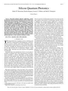
Anatomy of a directional coupler
Baribypass state
(11A directional coupler
or
can route a light signal straight through ( b a r b pass state) or switch it to an adjacent waveguide (crosdexchange state). Many such couplers can be connected together on a lithium niobate chip. When the couplers are joined in a pattern known as the dilated Benes network (an eight-input, etght-outNt version appears here), cross talk is minimized because any coupler can have only one of its inputs active at any instant. Color lines show one of many possible configurations of paths from inputs to outputs; dashed lines show unused paths that become active when the switch is reconfigured by altering the electrode voltages.
Directional couplers
_----- _--Yet other limitson integrationare the great length of directional couplers in relation to their width and the large minimum bending radius of the diffused waveguides. All these constraints add up to a maximum integrated array size of 32 by 32. Larger switching fabrics have to be built up by interconnecting 32-by-32 arrays. Another approach to guided-wave switching is time-division, rather than spacedivision, multiplexing. The division can be done by interchangingtime slots or by using multiple-access devices like star couplers. In time-slot interchangers, users are assigned slots on a single channel. Switching is done by a reconfigurable fabric that rearranges the temporal positions of the slots according to each’s destination. The slots are then separated and sent onward. The connection between users is virtual. In multiple-access switching, however, the connection between users is real and physical, albeit intermittent. For example, a star coupler network combines all its input nton-Switching with photorucs
channels and distributes them equally to all its outputs. Decoders on the output ports, instructed by a central controller, select the input they want to receive. SLOT INTERCHANGE. Most proposed photonic time-slot interchangers (EIS), when an input arrives in a given time slot, send it directly to the desired output time slot in a single step, over an optical-fiber delay line. The photonic interchanger based on directional couplers chooses a fiber whose length will delay the input slot just the right amount to fit it into the output slot. Work on this is being done at NEC Corp., Tokyo, and AT&T Bell Laboratories, Murray Hill, N.J.. The input is divided into time slots composed of many bits, with a little dead time between slots. That way, the coupler need not switch too often, and its low switching speed is not a handicap. Time slots for voice, data, and video users may be freely mixed. AT&T Bell Laboratories’ Disco system demonstrated the principle in an eight-byeight switching fabric.
Another kind of time-slot interchanger shifts the input slots through intermediate time-slot stages until they are in the desired output slot. With this scheme, the intermediate stages do not have to be fully connected or nonblocking, as they do in the single-stage interchanger. This time-division system is analogous to a multistage spacedivision network. One such system has been proposed by researchers at the University of Colorado, Boulder. Time-division multiplexing by multipleaccess fabrics may use a passive shared medium such as an optical-fiber ring. For input and output, the ring is accessed either by passive taps such as fiber couplers or by active taps such as directional couplers. In a synchronous ring, each user is assigned a unique time slot in which to read information from the ring. Other users can send information to a user by entering it into the destination user’s time slot. Access to the time slots is arbitrated by a central controller. Asynchronous, distributed-control 43
Authorized licensed use limited to: Utah State University. Downloaded on June 14,2010 at 19:19:47 UTC from IEEE Xplore. Restrictions apply.
The challenge with time-space-time buffer, then used to modulate a laser tuned schemes are another possibility. Like time-division fabrics, wavelength di- switching is timing. At 4.8 Gbls, the bits will to the wavelength of the designated output vision can rearrange input channels or share be only 208 picoseconds long, and, to pre- port. A star coupler eventually transports all them through multiple access. A wavelength vent discontinuities in the output channels, channels to receivers at the output ports. Control circuitry first checks the desired interchanger, for example, can switch a they will have to be synchronized within 10 wavelength-multiplexed channel-one com- ps. The onus for the timing falls on the ini- output port to see if it is busy, and, as soon bining signals at different wavelengths. Since tial time-division multiplexer, unless an elas- as it is not, turns on and tunes the input laser each user has a unique wavelength, a con- tic store (one whose delay time can be var- to the wavelength of the receiver at the outnection can be made between two users by ied) is placed at the input to the space- put port, finally commanding the FIFO buffconverting a transmitter's wavelength to division switch. Control electronics will have er to send its stored information to the laser. Free-space switching, although not as to recognize 10-ps time differences. that of the appropriate receiver [Fig. 21. To minimize the timing burden, compo- well-developed as guided-wave switching, In a wavelength interchanger recently proposed by NEC, the multiplexed input enters nents w illhave to be packaged with extreme is perhaps even more promising. Several an optical splitter, where its power is divid- care. For example, if optical fibers between laboratories are working on free-space sysed equally among a group of internal chan- the initial time-division multiplexer and the tems based on two-dimensional optoelecnels. Each channel subjects the multiplexed space-division switch differ by only 1 cm, tronic ICs such as self-electro-optic-effect input to coherent detection: the input is their bit amval times will differ by all of 50 devices (SEEDS), double heterostructure optoelectronic switches, and vertical surface ps (for an index of refraction of 1.5). mixed with a monochromatic laser beamtuned to a different wavelength for each RECONFIGURING FABRIC. A wavelength- transmission electrophotonic device arrays. channel-so that the information on the division-based photonic packet switch is an- QUANTUM WELLS. Of these devices, a symdesired input signal is electrically extract- other kind of a multidimensional fabric. It is metric SEED (S-SEED) is particularly useed. This electrical information is used to basically a multiple-access fabric that rapidly ful. Its structure lends itself to fabrication modulate a fixed-wavelength output laser. and continually reconfigures itself to time- in large arrays by batch-processing. An SThe various output wavelengths are then share channels. In the Hypass system pro- SEED is a pair of p-i-n diodes with multiple multiplexed and sent on from the inter- posed by Bellcore, Livingston, N.J., pack- quantum wells in the intrinsic region [Fig. ets of information entering the fabric are 31. The diodes are electrically connected in changer on a single optical-fiber channel. A promising multiple-access wavelength briefly stored in a first-in, first-out (FIFO) series and reverse biased. One of the diodes is on (reflects light) while the interchanger is based on a star other is off (absorbs light). Which coupler, a device that combines all Tunable diode is on is determined by the inputs and distributes them to all ratio of the powers of the light output channels. Each input has a beams directed at each diode. The unique wavelength. Each output reflected differential light beams channel has a tunable filter that a A7 XI, may then be processed through a central controller tunes individu- Input Output lens or hologram to subsequent Sally to match the wavelength of SEED arrays until they arrive at the input destined for it. the required output channel. Several kinds of tunable filter ,\" Tunable Laser Wavelengtl The strength of S-SEEDSis that are being pursued, including movhi XI, laser multiclexer laree arravs of small devices can able gratings,etalons (wavelengthI selective interferometers), and /Z]In wavelength interchanger, a multiwavelength input is divided be built. Using a gallium arsencoherent detectors. All devices among many coherent detectors. Heterodyned by a tumble laser, each ide-aluminum gallium arsenide have advantages and disadvan- coherent detector extracts an electrical modulation signal represent- heterostructure for multiple q u a tages. Movable gratings have good ing a discrete input wavelength and uses it to modulate a laser oper- tum wells, workers at AT&T Bell resolution but are slow. Etalons atingat a different wavelength.Any input wavelength can be switched Laboratories have fabricated, by molecular beam epitaxy, 128-byare fast but have less resolution. to any output wavelength. 256 arrays of S-SEED pairs. The Coherent detectors offer both weakness of the devices is that speed and high resolution, but are they require too much energy; at expensive to use because they need a tunable mixing laser. present they need about 1 picojoule to change state. Much TIME-SPACE-TIME. Multidivisional more work also remains to be fabrics-those based on a combiP+ done on packaging. nation of space-division and timeNevertheless, AT&T Bell Labdivision multiplexing-promise MuItlPl>\ p contact oratories has built a 16-channelhuge throughput with rather little quantum hardware. AS yet, though, such contact input, 32-channel-output SSEED-based fabric, an applicasystems are only in the concept Sillcon tion-specific version of its 32-bystage. One proposal, from AT&T 64 array. Operating at about only Bell Laboratories, calls for a 512- + 100 kbls, the fabric does not take by-512 time-space-time phototuc " advantage of the speed of Sswitch with an internal bit rate of lsolatlon SEEDs, but does demonstrate the 4.8 Gbls. The 512 input hes, each feasibility of free-space optical inat 150 Mbls, are partitioned into stack terconnection and packaging. An 16 sections of 32 lines. Each secincoming signal is routed to an tion is time multiplexed into a sinSubstrate output channel through six switchgle space channel, and all channels are fed to a 32-by-32 TSI,through /3] Lkhi entennga symmetric self-etectm-optic-effectdevice (S-SEED) ing stages. At each stage, the siga 16-by-16 space-division switch is either reflected or absorbed, depending on the ratio ofpower in the nal is split in two and directed to and then a 32-by-32 TSI, and fi- separate beams illuminating it and its neighbor. The multiple guan- an S-SEED pair. A control comnally demultiplexed into 512 chan- tum-well structures are alternating layers of gallium arsenide and puter determines which of the pair aluminum gallium arsenide, each layer about 10 nm thick. accepts the signal. The S-SEED nels, each at 150 Mbls.
r
I
/
"