A NOVEL, HIGH-SPEED, RECONFIGURABLE DEMAPPER SYMBOL DEINTERLEAVER ARCHITECTURE FOR DVB-T Laszlo Horvath, Imed Ben Dhaou, Hannu Tenhunen and Jouni Isoaho Electronic System Design Laboratory, Dept. Of Electronics KTH-Electrum, Electrum-229 Royal Institute of Technology, SE-164 40, Stockholm-Kista, Sweden e-mail: e92_lho,imed,hannu,
[email protected]
ABSTRACT In this paper, we propose a new, reconfigurable algorithm for signal demapping: MUSCOD algorithm, used in DVB-T (Digital Video Broadcasting, Terrestrial version) receivers. The MUSCOD algorithm / architecture supports both hierarchical and nonhierarchical transmission modes. It implements different modulation schemes supported by the standard. We also propose a highperformance, reconfigurable symbol and bit deinterleaver working in conjuction with the demapper. We implement the proposed architecture using 0.6µm 3.3V CMOS technology. The proposed architecture requires a system clock frequency of 36.57 MHz. It has a maximum throughput of 40.5 Mbits/s and dissipates 0.3 W.
apper and the inner interleaver is presented in Sections 6 and 7. Section 8 presents our conclusions. MPEG-2 Source coding and Multiplexing
Channel coding
To Aerial
Front End
Pilot & TPS signals Mapper Frame Adaptation D/A
OFDM
Figure 1. Block diagram of the DVB-T transmitter
2. DVB-T CHANNEL CODING 1. INTRODUCTION In March 1997, the European Telecommunications Standards Institute (ETSI) ratified a new standard for digital terrestrial television broadcasting called DVB-T [1]. The standard describes the various modulation and channel coding techniques used in order to provide acceptable video quality to the home viewer. This is done by transmitting MPEG-2 streams [7] using digital modulation techniques known as OFDM (Orthogonal Frequency Division Multiplexing)[9]. In DVB-T, the MPEG-2 transport multiplex stream is channel coded. The resulting coded stream is split into N parallel streams. Each of these stream modulates a separate subcarrier using conventional modulation techniques such as Quaternary Phase Shift Keying (QPSK) or Quadrature Amplitude Modulation (QAM). DVB-T uses three different digital modulation techniques: QPSK, 16-QAM and 64-QAM [8]. The DVB-T standard specifies two different transmission modes: 2k mode, employing 1705 subcarriers and 8k mode, employing 6817 subcarriers. The functional block diagram of the DVB-T transmitter is given in Fig. 1. In this paper, we propose a demapping algorithm, called MUltiSignal-COnstellation Demapping (MUSCOD). This algorithm is hardware oriented, computationally efficient algorithm. It supports both hierarchical and non-hierarchical transmission modes and three different digital modulation modes QPSK, 16-QAM and 64-QAM. Furthermore, we proposed an architecture for the demapper and the inner deinterleaver. We implemented the proposed design using 0.6µm 3.3V CMOS process. The rest of the paper is organized as follows: Section 2 describes the DVB-T channel coding and decoding. In section 3 we describe the mapping/modulation techniques used by DVB-T. In section 4 we derive the MUSCOD algorithm. Section 5 describes the inner deinterleaver. The hardware implementation of the dem-
In the DVB-T transmitter, the channel coding chain (Fig. 1) is designed to provide efficient error protection against byte and bit burst errors. Thus, the MPEG-2 transport multiplex packets are scrambled, Reed-Solomon encoded, convolutionally byte-wise interleaved (outer interleaver), then convolutionally encoded. The data-stream after the convolutional encoder is bit- and symbol interleaved. The resulting bit-streams are partitioned into v-bit words. Each v-bit word is then mapped to signal points selected from one of the of seven signal constellations (see Section 3). The resulting complex symbols are used to modulate N carriers, which is efficiently implemented using Inverse Fast Fourier Transform (IFFT). In the DVB-T receiver, the channel coding process is reversed. After FFT and channel equalization, the complex symbols are demapped to v-bit words. The v-bit words are deinterleaved by the symbol- and the bit-deinterleavers. A Viterbi decoder corrects bit-wise errors, then the data stream is deinterleaved by the convolutional deinterleaver. Byte-wise errors are corrected by the Reed-Solomon decoder. Finally a descrambler restores the original MPEG-2 transport multiplex packets.
3. MAPPING / MODULATION DVB-T specifies two level coding and modulation method which enables it to use hierarchical transmissions [1] [2]. In hierarchical transmission two MPEG-2 transport streams, referred to as Highand Low Priority streams, are transmitted in a combined signal. The HP stream is a low bit rate stream which can be received under poor or difficult channel conditions (low SNR) and the LP stream is a high bit rate stream which requires good communication channel (high SNR). In simulcast mode these two streams can carry the same programme in a low-bit-rate, rugged version
and one high bit-rate, less rugged version. In multicast mode totally different programmes can be transmitted, one low-bit rate programme - receivable by mobile receivers, and a high-bit rate programme - receivable by directed antennas. In hierarchical mode the receiver is only required to decode one of the two transport streams. The two modes differs by means of the channel coding chain, but they use the same inner interleaver. After the inner interleaver, the mapper is employed to convert every v-bits into one complex symbol, selected from a given signal constellation, corresponding to M-QAM digital modulation schemes, where M=2v. DVB-T specifies seven different signal constellations: QPSK (v = 2), uniform or non-uniform 16-QAM (v = 4) and 64-QAM (v = 6). The complex symbols after the mapper, are used to modulate orthogonally spaced carriers. For hierarchical transmission both uniform and non-uniform modulation can be used, and the convolution encoder can have different code rates for HP and LP streams. The non-uniform modulation has unequal distance between groups of constellation points, so that a signal carried by the QPSK constellation can be received at a lower SNR than the full constellation of 16- or 64QAM. An important parameter, when non-uniform modulation is used, is the modulation factor α, which can take on values 1, 2 or 4. When α increases the HP stream becomes more robust but the LP stream will require higher SNR. For non-hierarchical transmission uniform modulation is used with α = 1. Another important parameter is the code rate of the convolutional encoder, which controls the ruggedness of the data stream. The DVB-T system can be configured to be able to cope with a variety of different channel characteristics and application requirements, by selecting the appropriate inner coding rate and signal constellation. Simulated performance of the DVB-T system for combinations of different code rates and signal constellations can be found in [1]. Measured performance can be found in [2]. In the DVB-T receiver, after the FFT and channel correction, the demapper converts every incoming complex symbol into v-bit words, [y0,y1,..., yv-1]. It uses the value α and v to select the signal constellation used by the modulator. These values are carried by bits in the Transmission Parameter Signalling (TPS)[1]. In the following section, we are going to derive the MUSCOD algorithm used by the demapper.
4. THE MUSCOD ALGORITHM The MUSCOD algorithm uses special properties of the signal constellations to demap a given complex symbol into a v-bit word. The pseudo-code for the MUSCOD algorithm, used to calculate bits [y0, y2, y4] from the real-part (Re) of the symbol value is presented below: 1. Get the sign of the Re-part: y0 = 1 if Re < 0 y0 = 0 if Re > 0 2. Check if v > 2, otherwise go to step 7. 3. Check α: if α = 2 then alpha_plus = 1 if α = 4 then alpha_plus = 3 otherwise alpha_plus = 0 4. Calculate y2: y2 = 0 if Re > (v-2) + alpha_plus
y2 = 1 if Re < (v-2) + alpha_plus 5. Check if v = 6, otherwise go to step 7. 6. Calculate y4: y4 = 0 if (Re > (v + alpha_plus)) or ((Re < 2 + alpha_plus)) y4 = 1 otherwise 7. Calculation of [y0, y2, y4] is ready. Bits [y1, y3, y5] are calculated exactly the same way, from the imaginary-part (Im) of the symbol value.
5. INNER DEINTERLEAVER Inner interleaving consists of a bit- and a symbol interleaver. The interleaving process results in frequency interleaving, no time interleaving is used.
5.1 Symbol deinterleaver The symbol deinterleaver is a block based deinterleaver. It acts on blocks of 1512 (2k mode) or 6048 (8k mode) v-bit words. The v-bit words yin=[y0,y1,..., yv-1] from the demapper are read sequentially into a vector Yin=(yin0,yin1,yin2,...,yinNmax-1). The deinterleaved vector Yout=(yout0,yout1,yout2,.....,youtNmax-1) is defined by: youtq= yinH(q) for even OFDM symbols youtH(q)= yinq for odd OFDM symbols where q = 0,.....,Nmax-1 and Nmax=1512 in the 2k mode and Nmax=6048 in 8k mode. H(q) is a permutation function defined in [1]. Each OFDM frame consists of 68 OFDM symbols, numbered from 0 to 67. Thus, this procedure is repeated 68 times for each OFDM frame.
5.2 Bit deinterleaver The bit deinterleavers are block based. The block size is 126 bits, which is the same for each deinterleaver. However, the deinterleaving process is different. It works as follows: The symbol deinterleaver sends 126 v-bit words, yout=[a0,a1,..., av-1], to the bit deinterleaver, each deinterleaver receives one and only one bit from a given v-bit word. The most significant bit, a0, is sent to bit deinterleaver I0 and the least significant bit, av-1, is sent to I(v-1). For each bit deinterleaver, the input bit vector is: A(e) = (ae,0, ae,1, ae,2,...., ae,125) where e ranges from 0 to v-1 The deinterleaved output vector from each bit deinterleaver: B(e)=(be,0, be,1, be,2,...., be,125) is defined by: be,He(w) = ae,w w = 0, 1, 2,..., 125 where He(w) is a permutation function which is unique for each deinterleaver and is defined as follows: I0: H0(w) = w I1: H1(w) = (w + 63) mod 126 I2: H2(w) = (w + 105) mod 126 I3: H3(w) = (w + 42) mod 126 I4: H4(w) = (w + 21) mod 126 I5: H5(w) = (w + 84) mod 126 This block based bit deinterleaving process is repeated 12 times per OFDM symbol in the 2k mode, and 48 times for the case of 8k mode.
6. HARDWARE IMPLEMENTATION The demapper and the inner deinterleaver was implemented in hardware. In the following subsections we shall describe each component and our method for architecture optimization.
6.1 The Demapper
Control signals
Demapper
HqShR.
DemapperControl alpha_plus word v
(Im-part)
Ctrl sig. Data path
y0y2y4
(Real-part) sign bit + 4 bits
Mem Sel.
addr. & ctrl.
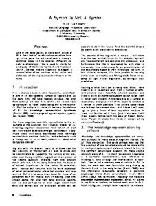
The block diagram of the demapper, given by Fig. 2, consists of the following hardware components: • HqShiftReg: Generates addresses corresponding to permutation function H(q). • Two DemapReorIm components: Hardware implementation of the MUSCOD algorithm. One operates on the real, the other on the imaginary part of a given complex symbol. • DemapperControl: The controller of the demapper. The demapper assumes that the complex symbols are represented with sign-and-magnitude representation: one sign-bit plus 4-bits. In order to correctly demap the received complex symbol, the demapper should be configured to the mode and modulation scheme used by the transmitter. The following control signals are used for the configuration: • TPS bits [s25, s26]: Gives the value of v. • TPS bits [s28, s29]: Carrying the value of α. • TPS bits [s38, s39]: The current transmission mode (2k or 8k). The max. input bit rate to the demapper is 67.6 Mbits/sec and the max. output bit rate is 40.5 Mbits/sec (using 64-QAM).
DemapReorIm
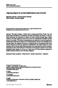
OFDM symbol is stored in the even “in RAM”. When the even OFDM symbol is demapped, the symbol deinterleaver moves the data from the even “in RAM” to its restored address in “out RAM”. Meanwhile, the demapper continues to demap the next incoming OFDM symbol (odd) and stores it in the odd “in RAM”. After the symbol deinterleaver correctly reordered and stored the even OFDM symbol, the bit deinterleaver reads it from the even “out RAM” and bit deinterleaves it. The symbol deinterleaver restores the address of even and odd OFDM symbol as follows: Given an integer value q, taking values from 0 to Nmax-1, where Nmax=1512 in 2k mode or Nmax=6048 in 8k mode, the symbol deinterleaver generates an integer value Hq, using a pseudo random binary sequence generator (PRBS). Hq has the same range as q (see Section 5.1). The symbol deinterleaver moves odd OFDM symbols from q addresses to Hq addresses. Even symbols are moved from Hq addresses to q addresses (see Fig. 3a). The design, presented in Fig. 3a, was implemented in VLSI using 0.6µm 3.3V CMOS process. The area of the chip without pads is 100 mm2 and it dissipates 0.4 W. The four memories occupy a large silicon area and increase the power consumption due to redundant operations. An optimized architecture of the inner deinterleaver is shown by Fig. 3b. By adding an Hq address generator to both the demapper and the bit deinterleaver, we were able to eliminate the need for a separate symbol deinterleaver and the same time reduce the memory requirements. In the improved design the two components share the two RAMs in the following way: While the demapper writes into the even RAM, the bit deinterleaver reads from the odd RAM and vice versa. The resulting optimized architecture is 30% smaller and consumes 25% less power (see Section 7)
3.a. Even RAM in
y0y1y2y3y4y5 DemapReorIm
y1y3y5
Hq Demap.
Figure 2. The architecture of the demapper
6.3 Optimizing the number of memories The initial design of MUSCOD and inner deinterleaver is presented in Fig. 3a. The figure shows the demapper, the symbol deinterleaver, the bit deinterleaver and four RAMs (Random Access Memories). The system works as follows: The demapper demaps one OFDM symbol at a time. An even
q q
6.2 Symbol deinterleaver The symbol deinterleaver is a component that works on blocks of data. Its task is to restore the positions of data words in a block of 1512 data words in 2k mode and 6048 data words in 8k mode. The restoration of even OFDM-symbols is different from restoring the odd OFDM-symbols [2]. The data reordering can be implemented as memory to memory transfer. Data from a memory can be moved to a different address in an other memory. The source and destination addresses are calculated according to the symbol deinterleaving algorithm (see Section 5.1).
yqout = yH(q)in
Odd RAM in
Symb. deint.
Even RAM out q q
Hq
yH(q)out = yqin
Bit deint.
Odd RAM out
3.b. From Frame demux and Channel est.
RAM for even OFDM symbols Hq q
Demapper q Hq RAM for odd OFDM symbols
To depunct. dev. and inner decoder (Viterbi) Bit deinterleaver
Ctrl sig. Data path Symbol deinterleaver Figure 3. a. Initial design 3. b. Improved design
6.4 Bit deinterleaver The bit deint. consists of the following components, see Fig. 3: • HqShiftReg: Generates addresses corresponding to permutation function H(q). • ReadHandler: A controller for handling memory access. • BitdeintControl: Controls the bit deinterleaving. • OutputControl: Synchronizes the transfer of the data to the depuncturing component. • MemSelect: Selects the memory based on the sign of the current OFDM symbol. • BitShifter: Bit deinterleaving is done by the bitshifter. It consists of six bit deinterleavers (I0, I1,..., I5). In order to reduce power consumption, only v of these bit deinterleavers are active, where v can take on values 2, 4 or 6 (see Section 3). The bit deinterleaver is configured to use the correct transmission mode by the following control signals: • TPS bits [s25, s26]: Give the value of v. • TPS bits [s28, s29]: Carrying the value of α. • TPS bits [s38, s39]: Information about the current transmission mode (2k or 8k). The maximum throughput of the bit deinterleaver is 40.5 Mbits/s using 64-QAM digital modulation. addr & ctrl interleaved data in
HqShR. Mem Sel.
Bit deint.
Ctrl sig. Data path
Bit Shifter
RAM odd Bit deinterleavers
Bit deinterleaver Controller
RAM even
Figure 5. The layout of the demapper / inner deinterleaver.
8. CONCLUSIONS In this paper, we proposed and implemented a reconfigurable, DVB-T compliant demapper and inner deinterleaver. By splitting the functionality of the symbol deinterleaver between the demapper and the bit deinterleaver, a 50% decrease in memory usage was achieved. This decreased the power consumption of the circuit about 25% and the size of the chip about 30%.
9. REFERENCES
ctrl Read Handler ctrl Bitdeint. Output Control ctrl Control
Demapper
accept deinterl. data out
Figure 4. The architecture of the bit deinterleaver
6.5 Memory requirements The memories are 8-bit asynchronous RAMs, each 6 Kbytes in size. This will allow each RAM to store the maximum amount of data from an OFDM-symbol. In 8k mode, 64-QAM modulation this amount is theoretically 6 x 6048 bits= 4.42 Kbytes but in practice 8 x 6048 bits = 5.91 Kbytes is used since the memory has 8 bit wordwith. The selection of asynchronous memory helps to reduce clock skew and minimize the power consumption.
7. VLSI IMPLEMENTATION We used a 0.6µm 3.3V CMOS process to implement a VLSI architecture for the demapper / inner deinterleaver and the 2 RAMs. The operating frequency of the circuit is 36.57 MHz. The maximum throughput of the demapper / inner deinterleaver is 40.5 Mbits/s (64-QAM). The estimated power dissipation at the layout level is 0.3 W. About 70% of the power is consumed by the bit deinterleaver shift registers. Further optimization of the design will be needed to reduce power consumption. Fig. 5 shows the layout of the demapper / inner deinterleaver circuit, including the 2 RAMs. The area of the chip, without pads is 69 mm2.
[1] ETSI: “Digital Video Broadcasting (DVB); Framing structure, channel coding and modulation for digital terrestrial television” - EN 300 744 V1.1.2 [2] ETSI:”Digital Video Broadcasting (DVB); Implementation guidelines for DVB terrestrial services; Transmission aspects” - TR 101 190 V1.1.1 [3] DRURY, G.M. “DVB channel coding standards for broadcasting compressed video services”, Electron. & Commun. Eng. J., pp.11-20, Feb. 1997. [4] REIMERS, U.: “DVB-T: The COFDM-based system for terrestrial television”, Electron. & Commun. Eng. J., pp.28-32, Feb. 1997. [5] Mitchell, J., Sadot, P., “Development of a digital terrestrial front end”, International Broadcasting Convention 12-16 Sept. 1997, IEE Conference Publication No. 447, pp.519524, ISSN 0537-9989 [6] Anikhindi, S., Cradock, G., Makowitz, R. and Patzelt, C., “A commercial DVB-T demodulator chipset”, International Broadcasting Convention, 12-16 Sept. 1997, IEE Conference Publication No. 447, pp. 528-533, ISSN 0537-9989 [7] Rodriguez, A., Fibush, D., Bilow, S., “MPEG-2 Fundamentals for Broadcast and Post-Production Engineers - A Video and Networking Division White Paper”, http://www.tek.com/ VND/Support/White_Papers/Profile/mpeg2.html [8] Proakis, J. G., and Salehi, M., “Communication Systems Engineering”, Prentice Hall, 1994, ISBN 0-13-158932-6 [9] John A. C. Bingham, “Multicarrier Modulation for Data Transmission: An Idea Whose Times Has Come”, IEEE Communication Magazine, 37, pp 5-14, May 1990. [10] Gray K.Yeap, “Practical Low-Power Digital VLSI Design”, Kluwer Academic Publishers, 1998.