Program for Checking. Functional and. Timing. Compatibility of Synthesized. Designs* ... RTL designs. This approach uses a hybrid numeric/symbolic simulation.
A
Hybrid
Numeric/Symbolic Timing
Program
Compatibility
for
of Synthesized
Chih-Tung
Chen
Department
and Alice
Engineering California
CA 90089-2562
Abstract
of constraints; lack
In
this
paper,
we pn.xent
for
approach
uses
a hybrid
the
functional
to
extinct
taking
into
and
perform
which
clocking
The
was then
data
scheme
and
of this
problems
Control
the
Signal
corrected
are also related Hence, and
was
This ing
(CSG)
accordingly.
tool timing
presents
RTL
designs
applicable
to other
synthesis
design
flow.
Due the
to the
critical
systems one
cost
of engineering
marketing
should
may
time,
that
the
fabrication
design
be eliminated
argue
and
at
all
errors
of
costs.
Although
synthesized
designs
be correct
by construction,
in reality
there
guarantee
unless
synthesis
process,
ing
techniques
dated. like
the and
However,
cation
synthesis
if not
the
can
[9].
system for
A more
synthesized
be
a large
impossible,
techniques
to verify
programs,
to validate
a high-level
practical,
whole
with
digital
so that
this
vali-
is still
abstraction, as early
it is desirable as possible.
sis system ●This
can be verified
may work
In
produce was
to find many
supported
thors
considered
and should
the official Research
not
policies, Projects
in this
2
is
to their
by
Agency
levels
of
design
problem
a high-level
synthe-
designs the
for
a given
Advanced
document
expressed
are those
as necessarily or implied,
or the U.S.
$03,00 @ 1994 IEEE
as the
but the
timing
specifi-
found
also
only
can
be ef-
task.
verify
take
that
properties
checking
to not
a by
into
Using
the design account
the
the
data
path
and
controller
issues,
such
aa delays
and
for design
verifica-
the
scheme.
Related
ods
au-
representing
found
ture
(DDS)
sign
structure
lations
Government.
not have
of approaches a survey).
practical
which
with
similar [7].
and
Winslett
can
achieve
the
ability
automatically.
and
some
The
user
to modify
check
the
consistency
to repair
on a for-
Data
the
Their
one we
objectives.
relies
Design
RLEXT
only
of our
which
ADAM
meth-
simulation-
[8] is the
system
allows then
formal
limitations.
and
to the It
However,
at present
theoretical
is a rule-based
model
design
of the Advanced
still
by Knapp
RLEXT mal
are a variety
ones
have
Research
of the
are
bssed
set
Work
(see [3, 10] for
system
112 0-81 86-5785-5/94
formally between
There
by the Federal Bureau of InJFB190092. The views and
be interpreted
either
any
addition,
Projects Agency and monitored vestigation under Contract No. conclusions
at various
we are able
We
technique
the
also
are derived
behavioral common
simulation
is
motivated
designs
several
tq perform
ADAM
im-
tion designs
symbolic
approach,
is
system.
possess
utilized
clocking
specifications. Although
the
aa well
ADAM
for check-
USC
verifi-
alternative respect
the
designs
interaction
system
formal
in
functionality
includ-
formally
RTL
fectively
is no such
formally
practical
these
should
software
current
designs
and
[11]
efficiently,
incorporating
approach the
func-
system.
the
systems
from
need
technique
the structural
manner
of the
the
approach by
This
Our
that
in a well-defined
both
designs
an efficient system.
timing
synthesis
produced
funcdesign
is a strong
check
of synthesized
synthesis
cations
can
in a high-level
the observation
Introduction
which
pure
many
and
there
is a
are being
hand,
because
that
high-level
similar
1
enough
there
designs
to the control
paper
the
the
On the other
we believe
an automatic
tionality
an early
Genemtor
errors
verification,
while
is not
to be integrated
to
work
with
validation
for
proper
or compared.
tional design.
while
procedure
value
to identify
of the ADAM
software,
a design
between
as the
task.
by its ability
version
simulation
of
intemction
This
without
of sense of correctness
evaluated
effective
designs.
a gmph-comparison
the checking
shown
behavior
as well
employs
and
RTL
numeric/symbolic
the
paths
and
an e~cient
synthesized
account
control
delays,
checking
and
C. Parker
of Southern
Los Angeles,
Functional
Designs*
of Electrical
University
approach
Checking
Structhe
de-
of the
some
design-rule
vio-
approach,
however,
does
not
mention
tween ing
the
the
issues
handled
such
bolic
simulation
expanded
structs is not
powerful
domain tion
till
is
early
form
for
the following
opemtion unit
values
I
1,
properties:
op
u in
op and
con-
Consequently,
in
CDFGS,
such
that
u can
op is achieved
of op to the
by di-
corresponding
of u.
the noncon-
there the
of
it
each
exists
source
op.
The
and
source
unit buses
3.3
dependence
interconnect the
unit
of a functional
which
data
an
of val
set up by using
tations
that
For
the functional
Property
verifica-
paper
3.2
CDFGS,
perform
u
and/or
CDFGS have
is
can
or a stomge
in
I
be-
element.
dejines
input
designated
to
be an output
switching
to be done
op)
in
corresponding
which
of val
(val, path
port
The path
is
devices.
the
required
in I for
every
compuexecution
instance.
to the synthesis
In fact,
and timing
the
generally
and the implementa-
specification
each
the input
Property tween
evaluation
behavior
For
the required
[11].
have
to perform
ports
port
this
looping
in this
important the
In
to
the
functional
applied
all
input
register-
due
and
show
when
run.
and
will
exz”sts a functional
recting
over
[2] on
of symbolic
the functional
from
correctly, 3.1
to deliver
synthesis)
of op-
the
1980’s
general
we will
are equally
is derived
(control
be configured
symbolic
activities
conditional
useful
both
at
there
sym-
in a single applied
a controller
signals
if mapped
compati-
behind
manipulation
this
level,
very
where
the
by
enough
RT
of a design
simulation
a number
first
research
algebraic
caused
at the
are
behavior
so that
verification
The
Although
can be made
circuit
values
at IBM
lasted
of the
[1].
trol
tim-
delays
idea
can be simulated
[5].
determinacy
and generating
be-
the
timing
The
evaluate
hardware
only
weakness
and
and
chips.
researchers
level
problem
How
scheme
functional
is to
to
transfer
tion
the
conditions
simulation
interaction
Property
synthesized
1970’s,
the
numeric/symbolic
sets of signal
erating late
nor
controller.
clocking
hybrid
to check of the
the
described.
work,
bility
logic,
and
as the
is not
In our utilized
control
datapath
example,
in a well-defined
information
available this
means
regarding
after
the
information
of bindings
these
properties
synthesis
is represented
in ADAM’s
DDS
is
process.
For
explicitly
by
representation.
manner.
4 Properties
3
of Synthesized
Approach In order
The
problem
briefly
described
Show
are
solving
here
can
be
j70w
implementation
computation
graph
specified
CDFGS
for
every
I will
in the conexecution
implementation
which
consists
asked
in this
of a data
between
input
we can
faithfully
CDFGS
ties.
This
difficult are
or
which
/output
not
problem
like
precision NP
determining
if NP
Fortunately, mapping
trol
steps
as two
on the
if
graphs
are
cannot
the
assigning path
the
and design
described
twofold.
and
the
design
they
both
timing
time
in terms
for
over
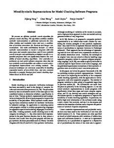
Figure
1 shows
equivalent,
the
DDS.
Second,
a similar
a flow First,
It includes
chart the
the
which
design
behavioral
the physical
of two finite-
available,
and
library.
P
proofs).
operations
the
simulation
ing,
and
wiring
the
tasks
such
flow
of
of the
The
and
...
L 13
such
input/output
design
hybrid
is analyzed
the
we
as delays
and
if
set
clock-
We estimate
is provided.
The
to produce
up
the
control
a list
of all
paths.
symbolic It
from
information
Next,
protocol.
if the floorplan
execution
event-driven.
and binding),
module
parameters
the
delays
possible
to con-
the
illustrates
is read
specification,
implementation,
major
with since
form
briefly data
structural
in
the sym-
synthesis
a simple
the
into
scheme,
as a CDFG. approach.
be done
re-
to take
for comparison
in
our
a symbolic
of the clocking
high-level
be represented
for formal
we are able
are ready
specification
3.
provides
protocols.
results
procedure
simulation
operates
input/output
can
simulation
in Section
it
simulator
at the same
simulation
our
operations
allocation
symbolic
First,
account
enti-
1 is actually The
1
combines
checking we devel-
a behavior-comparison
are
the
for
effectively,
to use symbolic
to showing
Even
(see [4] for
CDFGS.
if
of I,
independent
implementation
(data
even
which with
tool
and
motivations
domain,
bolic
an automatic quickly
properties
because
delays,
behavior
is similar
assigning
while clocking
correctness
intractable.
CO-NP
(scheduling),
to hardware
the
the equivalence
from
involve
outputs
specified
dynamic
expressions #
the
of a mapping
this
be
relation-
However,
prove
dataflow
to
and
the
the problem
algebraic time
this to
two
is believed
values
based
sults
We are
dynamic
protocol.
regarded
is because
whether
result
RT level
The
structure
a controller.
the
under
obtain
very
and
of inputs
operated
and
and
path
is a static
to obtain
sequences
scheme is still
1 itself
problem
I is physically
nor
an approach
approach
The
it
designs
at the
in-
stance.
ship
to produce
synthesized oped
or not the RTL
the required
data
we
as follows:
whether
perform trol
which
Overview
Designs
simulation
is a hybrid
model
performed because
next the
is
data
START
E
no
rssd dssign data from dds
collision errors ?
setup simulation psrametars
Exscutaion Paths
no
* no
1
\
u
diagnosis proOSss
&& Figure
1: A flowchart
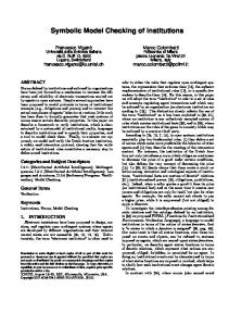
Figure
2: Execution
In
our
from
is evaluated
simulated will
simulation
so that
A transport
delay
tion.
Due to lack
of space,
ing checking simulator value
will
collision the
not
on the
to determine
the
the delay
wires.
the cause. by
the
If any
actual
operations
The
a dataflow
in the
simulaand tim-
paper.
Finally,
problem procedure
parison two
result
is called
describes
data
transfers
done
and
simulation
graphical
specification.
possible until
design
no more
errors.
The
is
discussed
a synthesized
design
required
operations
data the
data
transfers
circuit ations
and
data
and
at the same
trol
and
simulation
earlier,
modeling
terms
transfers time
of the
timing. here
Also, and
data
in the
exercising The
hybrid
performs
the
A path
direct
in
path
the
shown each
that
state-
in Fig-
of which
is
represents
the
is an assignment
for
path.
condition
symbolic
alternative
Element
Data
Path
The
values
paths
which
through
together
de-
the state-tmnsition
evaluation
from
behavioral
the
oper-
the con-
storage,
this
if any,
tate.
Normally, time.
114
component this
used The
defines
the
possible
If the
on
four-function
input
is invalid,
func-
manipu-
condition
a simple
to
information
condition
its
of
outputs
and
are set to unknown. (nets)
values.
value
are
used
A carrier
requires
at most A
3.
carriers port
1Currently, we acyclic. Techniques
task.
Figure
the symbolic one output
each
evaluated
datapath
than
for
on its
is available
tables.
module
For example,
in
being
of the
of function
data
lines,
is shown
at any
symbolic
form
of symbolic control
gating
datapath
exactly
of a datapath
The
the
the
depends
information
We represent
in
table
module
this
model
the module.
tion
data
of
In DDS,
internally
a module
many
of a datapath
model.
ALU
of
Evaluation
behavior
the
the
timing
to extract
symbolic
occur
5.2
5.1
lation
for
sequencing
instance.
to be able
that
to be described
the
is repeated
it performs
control
to emphasize
the
these
to find
is important
or not
a
graph paths,
condition
along
is
state
controller.
execution
a path
made
implement
what
to the
we need
in
between
and the correct
are related
behavior
comcom-
Simulation
is whether
Hence,
is the
process
path end
gmph.
are left.
for each execution
errors
design.
whole
an
by the
If
is called
with
of Boolean
termine
the
result
difference
paths
Symbolic
As we have
design
any
procedure
execution
Hybrid
5
finds
a diagnosis
to
of an FSM
three
assumptions
a set
of the simulation
graphical
procedure
proceeds
of Definition
which
the
graphs,
simulation
the state-transition
2 contains
is found
graph
the
with
the
graph
to another.
execution
state
gmphl
associated
The
occurrences
An
initial
For example, ure
design.
pared
model, path
5.1
an
transition
signals simula-
in this
monitors
from
is
the
modeling
a diagnosis
represented
controller
control
is used
be elaborated
simulation,
data
all
the
throughout
model
also constantly
during
but
1, 0 or unknown
tion.
of a state-transition
ofourapprosch
symbolically
numerically
be either
paths
one execution
Definition path
I
Path Corrdiiion
Ela
graph comparkm
hybrid symbolii simulation
1
y-
those
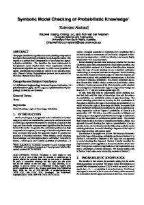
one tristate collision
for
connecting
propamore
outputs
to be tris-
output
is enabled
occurs
require the state-transition to handle cycles are under
if two
or more
graph to development.
be
during
so
so
c
•E
B
c
S1
SI
*
the
representing with
00
A+B
pared
01
A-B
isomorphism
10
A&B
This
11
AIB
lation
propagation
delay.
10 ns
output
ports
type
3: A four-function
drive
of design
a carrier
error
ALU
at the same
can be essily
detected
fication
[8]. This
and
symbolic this
Controller The on
controller its
is evaluated
clock
state
signal.
transition,
controller tion
moves
path.
path
The
and
appearing
then
a =
dition.
On
transition
lator
b =
the
aborts
the
5.2
current
execution
our
operations build
tex
ation
symbolic
unit
in the
symbolic
graph,
data
flow
operation
reports
a
specification.
graph
is the
predecessor.
the
ports
predecessors
to
tations
A ver-
the
a new
operation
the symbolic
ecution
Our
model
of a functional
der
is different
from
at
the
the early RT
level
operation
works
[5,2]
the
following
in
graph
on
Before DFGs
sions
overhead
ing the that
actual
occur we
since
data
in the
2. A powerful since
to propagate
is eliminated
operations data
algebraic do
not
the
try
algebraic
we focus and
only
expres-
This
transfers
is not
required
Lemma
path. manipulator to
simplify
the
dence
expressions
6.1
required
the
values.
the
ezists and
one ex-
pc.
If the
symbolically
un-
predicate
is a data of each op
under
property to establish
pc. between the
input/output
is important to compare
I for
result
to true
primary
are avail-
properly.
is interpreted
need
sure
of the designated
condition
the
in-
making
operation
pc,
propercompu-
execution
by
ports
path
that
implemen-
required
of simulating
we first
DFGs
property
several
every
the isomorphic
There
between
put/output
115
point
this
RTL
done
is configured
such
correspondence
is
efficiently.
the
for
result
for all their
the starting
on
the
are
is evaluated
DFG1,
respondence
on collect-
data
and
there
Consequently,
have
perform
condition
we present
from
between
In fact,
them
input
under
DFGs
3).
based
CDFGs
which
in DFGs
execution
of a mapping
them.
will
path
of its
Property
CDFGS
same
eration
ways: 1. The
between
that
be the
a set
corresponds
relationship
(see Section
of each
instance
the
flow
simulation
unit DFG1
one
a strong
computations
specification
performed.
symbolic
1 for
from during
is actually
of which
correctly, by
derived derived
1 is the result
1 will
values
functional Let
of the
The
CDFGS
3, we know
specified
of comparing
CDFG1
each
hybrid
of the RTL
problem
however,
able at the corresponding
the
the
Isomorphic
Section
input
the verification
to compare
In summary,
stance.
of an op
the
Similarly,
ties.
5 performs
procedure
1, if mapped
same
during
result
unit,
at the input
direct
whenever
is produced
value
and
are used is the
tation
the
to be
The
property
The
has
model.
exists
developed
speci-
only
Section
(DFG),
a graph-matching has been
model,
in
and CDFG1
From
values
which
by a functional
appear
become
being
or
its direct which
the
simu-
is based
design
this
of simulating
an isomorphic
Data
the simulation
flow
If a symbolic performed
values
the
during data
value
becomes
Symbolic
used for the design
is created
eration
of
produced
simulation.
for the
and
CDFGS
con-
simu-
problem.
into
CDFG1,
there
the
in this
and
the design
CDFGS,
our
comparison Since
graphs,
graphs
result
symbolic
described
dataflow
Because
cur-
path
input
the
6.1
model,
a bipartite
represent
the inputs
violation.
simulation
simulation.
to
value,
path
the
graph-
later.
implementation
translated
specification
of dataflow
b respectively,
if a required
control input
paths.
to the
an unknown
execu-
values
structural
1 becomes
two
that
behavior model.
for us. Therefore,
the
transition.
requires
be added
Representation In
state
i2 are a and
hand,
contains
data-dependency
at each
a
the
execution
if the symbolic
and
other
in the current
transition
O will
in
and
of the current
O and
at il
1 and
state
state
results
computed
the
simulation
task
the
to solve
represented
implementation
is a change
change
are
if necessary,
if the state
there
clock
condition
i2 to be 1 and
rently
the
outputs
to the next path
is updated,
For example, il
If
the
when
reason
applied
graph
is already
extracted
ulator.
flow
of the
using
flow
is com-
Verification
approach,
behavior
by the sim-
data
result
to be discussed
the
Graph-Based
on the data
time
specification
is also
the
simulation
property
can be effectively
6
Instead, the
the
difference
In our Figure
simulation.
graph
because these
two
an
one-to-one
DFGI
for
cor-
values. it provides
graphs. correspon-
the primary
in-
The
detailed
theorem
proofs
can
of this
be found
short,
this
correspondence
cause
of the
input/output
how
to
apply
the
corresponding DFGs
that
be performed time
and
data
because
mainly
be-
determines
1 and
obtain
Create an attribute
I
functional
unit
will
each and
properties
in
should
will
I (find
by
if I
is
6.2
output
For
have
simby
the cones Cs
such that
(outs,
of the corresponding
outI)
and C12 of outs
of DFGS and outI
●
thair attributea
●
all cerreaponding
are nifi end input
valuee
hava same
attributes I
F
t
pri-
and DFG1,
respectively
>
they are of the aema typa;
Give a unique
each pair
values
operationa
●
pri-
be explained
input values
t
at some
corresponding
DFGI
which
ID to each pair of primary
will
be preserved Hence,
of the
Give a unique
between
in DFGs
in CS and Cl
t
theorem.
Theorem
for all vertices
the
I is synthesized
interconnection.
of DFGs
the following
In
which
operation
dependency
correctly,
geometric
mary
exists
a proper
outputs
ilar
[4].
property
by a designated
synthesized
to
isomorphic
each required
every
establishing
mary
values
equiv_check(C~,CJ
following
values.
DFG1
a way
the report
is established
input
the
and
such
and
technical
protocol
output
Intuitively,
lemma
in our
ID to
.
all operations
●
each aet of corresponding
being
are
end output
values
I
+
I
isomorphic.
found,
yee
The
isomorphic
implies
that
tween
there
their
and
edges
is preserved,
but
of corresponding
words,
if
the
they
must have
the
6.2
A
Graph
be of the
Knowing
to
that
In fact,
all
morphic
there
theory, the
cones
the
correspondences
of the
put
values
ss soon put
as they
values
general
are
problem
we developed
that
each a vertex whose
In other
attribute
ia nil
operations,
they
are
values,
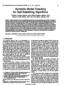
Figure
is an isomorphic
execution
behavior
comparison.
output
type
Based checking
let
the
inputs
Cs
Cs
and
toward
because
is not
established
turns
fals~
outthe
is any
C1 be their
primary
outputs
true
is returned.
7
Experiments
and
of
cones
to
to estaband
values
from
the
primary
outs
and
outI.
whose
(no ID is tagged), CS
Outl output
tries
operations
or value
otherwise,
out-
and
respective
basically
incrementally
operation
outs
of corresponding
of the
CI
check
corresponding
4. Let
procedure
the
there
and
and
This
isomorphic
of two
be a pair
correspondences
between
it is
cones
the
If
correspondence
this
C1 are
procedure equivalent
reand
be established and
the
and
for
in Figure
DFG1
between
Furthermore, can
whereas for
values input
advance.
are typelesa. a procedure
output
same
problem,
and
values
the
as shown
be checked.
in graph
property
primary
operations
are of the equivalent
are iso-
lish
unsolved
of their in
or not
values
problem
between
values
DFGs
paths.
the isomorphic
two
put
whether
4: A procedure
property
be-
straightfor-
isomorphism
known
property
it becomes for
corresponding
of
no
Procedure
is an important
are
If
‘1’
be-
the incidence
are
to do is to check
to check
correspondences
requires
corresponding
general
which easier
also
type.
a method
all the
the
that
are compatible.
CDFG1,
we need
for
Unlike
only
correspondence
vertices
same
C1 not
bitwidths.
and
of their
Cs and
such
Matching
develop
the cones
much
same
CDFGS
ward
vertices
corresponding
they
tween
between
is a one-to-one
vertices
relationship pair
property
all
vertices
on this
their
in-
in
the
In order
principle,
to show
we performed
the isomorphic
signs 2A cone of a vertex v in a graph G = (V, E) is a subgraph C = (V’, E’) such that 1. V’ = { v } U predecessors(v) for all VI, V2 in V’ if edge (VI, V2 ) in E then (VI, ~) is 2.
fact,
also in E’.
were
116
synthesized our
fied
that
trol
signal
the
a number from
preliminary the controllers generator
incorrect.
CSG
effectiveness
of our
of experiments the
USC
experiments tool
was then
ADAM
the
system.
immediately
generated (CSG)
approach,
with
by the [13] for
revised
In
identi-
ADAM these
de-
condesigns
accordingly.
Shortly with
after
CSG
was
a non-pipelined
for scheduling and
AR
and MABAL
binding.
This
●
It has 4 time
●
Both
we
References
experimented
MAHA
[12] was used
[6] for datapath
design
[1]
allocation
is characterized
as follows:
and output
values
non-overlapping
are not
clocking
[2] W.E.
latched.
scheme
is [3]
controller
execution
generated
path
carried
out
with
by
four
by holding
CSG
states.
the
ports
during
symbolic
values
from
the output
4th
cycle.
The
cones
then
extracted
built
during
with
the
the ones specified
We
also
whose previous
one.
ilar
except
way
latched. and
The
this
with
The
design
a robot
was
implementation
has
paths.
using
status
The
registers.
the
a sim-
[6] K.
be
constant
values
required
plied
externally,
input
were
which
results
In
[7]
to be sup[8]
use of
values
output
Some
were
unnecessarily
routed
to
ports.
of the input
values
continuing
under
were not
latched
as spec-
[9]
to
experiment
development,
with
including
video
other
de-
compression
Kugiikgakar lnt.
Conclusions paper,
automatically
we have
the verification tional
task.
approach,
and
Further critical ity ing
have
the
during
delays
and
verification. loops
needs
to
both
the
In
Automation
A.C.
Conference,
Parker.
for Module
Journal
D.W.
MABAL
And
of Computer
Knapp
D.W.
and for
Bus
Aided
- A
Allocation. VLSZ
Design,
A.C.
Parker.
Design
A
Unified
Information.
In
Rep-
CHDL-85,
1985.
Knapp
and for
ath
Hardware,
mal
Methods
M.C.
M. Winslett.
Linked
for
A Formalization
Representations
In IFIP
Workshop
Correct
McFarland. Hardware:
VLSI
of
of Datap-
on Applied Design,
that
symfunc-
using our
[12]
M.C.
For-
November
this
to take In
whose
approach
to demonstrate into
account
addition,
to be handled
timing
of Integrated
M.C.
McFarland,
posano.
Tutorial
Hill,
NJ
Parker,
Pizarro,
ACM/IEEE
for Design
in
AT&T
Verifica-
Bell
and
Labo-
R.
Synthesis.
Automation
J.
on and
07974-2070.
A.C.
Program
Circuits
Lessons
on High-Level
Parker,
of Sequen-
Transactions
1993.
Synthesis.
Design
A
May Practical
High-Level Murray
23th
CamIn
Conference, and
Datapath
M.J.
25th 1988.
Mlinar.
Synthesis.
Automation
In
Conference,
1986. [13]
designs
Design
ratories,
A.C.
Verification IEEE
McFarland. and
MAHA:
efiicient. with
Formal A Tutorial.
633-654,
pp.
ACM/IEEE
designs.
conducted
indicate
[11]
of
facilitate
a hybrid
checking
of synthesized
be performed
and the advantage
properties
designs
been
results and
experiments
should
for
compatibility
effective
the
We also presented
experiments
is indeed
RTL
approach
and timing
Several
identified
synthesized
bolic/numeric
Ver-
Verification.
1989.
tion
this
and
Package
Systems, [10]
In
Design
Computer-Aided
chips.
8
of Program
to Hardware
ACM/IEEE
tial
are
Application
CEng 1993.
1989.
ified.
signs
The
Correctness
Conditional
We
Darringer.
resentation
ports.
the
May
June
following
in inefficient
Approach
Report
Techniques
1988.
Compatibility
California,
Elsevier,
the
A Symbolic
and Timing Technical
Software
conclusions: All
July
1979.
We were able
with
and Survey
Computer,
Designs.
16th
was
Functional
18th 1981.
Verification
of Southern
ification
steps
Formal
Introduction
Univ.
93-26, [5] J.A.
12 time
implementation
Chen
of Synthesized
the
to
Correctness:
In
Conference,
P. Prinetto.
Parker.
controller
RTL
and
Au-
Functional
SDL.
Automation
and A.C.
was
values
P. Camurati
for Checking
graph.
in
inputs
Design
for
and
C.T.
[4]
were
than
ACM/IEEE
Simulation
ADLIB
IEEE
controller
synthesized
the
execution
arm
complex
Symbolic with
Research.
correctly flow
Cory.
Verification
Design
1990.
of Current
the
which
data
more
we required
by CSG
to verify
in the original
is much
RTL
graph
compared
Conference,
- Techniques
ACM/IEEE
was at
values
Simulation
In 27th
of Hardware
at the end of the
output
flow and
flow
16 possible
generated
data
experimented
control
ports
Symbolic
one
(symbolic)
and obtaining
of these
simulation
only
experiment
values
the execution
from the
contains
The
input
the input clock
Bryant. Applications.
tomation
used. The
R.E. and
steps.
the input
A two-phase
●
revised, filter.
is
our
abil-
design
tim-
J.P.
Weng
Synthesis CEng 1992.
data-dependent in the future.
117
and
A.C.
Parker.
in the ADAM
92-03,
Univ.
System.
of Southern
CSG:
Control
Technical California,
Path Report April