200-206, 2008. [17] S.-K. Fan et al., âManipulation of multiple droplets on N Ã M grid by cross-reference EWOD driving scheme and pressure-contact packagingâ,.
Synchronization of Concurrently-Implemented Fluidic Operations in Pin-Constrained Digital Microfluidic Biochips∗ Yang Zhao1 , Ryan Sturmer2 , Krishnendu Chakrabarty1 and Vamsee K. Pamula2 1 Duke University, Durham, NC 27708, USA 2 Advanced Liquid Logic, Inc., Research Triangle Park, NC 27560, USA Abstract— The implementation of bioassays in pin-constrained biochips may involve pin-actuation conflicts if the concurrentlyimplemented fluidic operations are not carefully synchronized. We propose a two-phase optimization method to identify and synchronize the fluidic operations that can be executed in parallel. The goal is to implement these fluidic operations without pinactuation conflict, and minimize the duration of implementing the outcome sequence after the synchronization. The effectiveness of the proposed two-phase optimization method is demonstrated for a representative 3-plex assay performed on a fabricated pinconstrained biochip.
I. I NTRODUCTION Digital microfluidic biochips are emerging as a promising solution for integrating fluid-handling on a chip [1]–[3]. Discrete droplets of nanoliter volumes can be manipulated in a “digital” manner under clock control on a two-dimensional array of electrodes. Compared to traditional bench-top procedures, a microfluidic biochip offers the advantages of low sample and reagent consumption, less likelihood of human error due to automation, high throughput, and high sensitivity. Recent years have seen a steady increase in the level of integration, system complexity, and applications of digital microfluidic chips [1]. Enzymatic assays [8], DNA sequencing [1], and immunoassays [9] have all been successfully demonstrated on a digital microfluidic chip. Recently, cell-based applications have also been demonstrated on a digital microfluidics platform [3]. These advances in technology serve as a powerful driver for research on computer-aided design (CAD) tools for the design of such chips. Architectural synthesis, physical design, and dropletrouting methods have been developed for the automated design of such chips that can execute laboratory protocols [11]–[16]. In a digital microfluidic biochip, a liquid-based bioassay protocol is implemented through a basis set of operations (such as DISPENSE, TRANSPORT, MIX, SPLIT) by manipulating discrete droplets of nanoliter volumes on a patterned array of electrodes. Each fluidic operation is executed by applying its corresponding pin-actuation sequence to the electrodes. Based on a precomputed bioassay schedule, several fluidic operations are implemented concurrently. If the target biochip is controlled using a direct-addressing scheme, i.e., each electrode is controlled by a separate pin, these fluidic operations can be implemented concurrently without any pin-actuation conflict. However, the direct-addressing scheme leads to a large number of control pins and high fabrication cost [8]. Therefore, several ∗ This
work was supported in part by the National Institute of General Medical Sciences of the National Institute of Health (grant # R44GM072155) and the National Science Foundation (grant # CCF-0541055).
pin-assignment methods [8], [17]–[19] have been proposed to design pin-constrained biochips. However, in a pin-constrained biochip design, concurrent implementation of fluidic operations during the same time interval may lead to pin-actuation conflicts, since their corresponding pin-actuation sequences are not completely compatible with each other. Therefore, pin-actuation sequences for the concurrently implemented fluidic operations need to be efficiently synchronized to avoid pin-actuation conflicts. Furthermore, applications such as toxicity screening require rapid time-to-response [7]. Therefore, the length of the outcome sequence (measured in terms of the number of vectors) after synchronization must be minimized. In this paper, we propose a two-phase optimization method to synchronize the fluidic operations that are executed concurrently. The proposed method is based on fine-grained parallelization of the corresponding pin-actuation sequences, such that pinactuation conflicts are avoided. The first phase involves the merging of pin-actuation sequences based on clique partitioning in graph theory, and the second phase targets the parallelization of pin-actuation sequences. We propose an integer linear programming (ILP) solution and a heuristic method for the second phase. A multiplexed and concurrent bioassay, namely the n-plex bioassay, is implemented on a fabricated pin-constrained biochip, in order to evaluate the effectiveness of the proposed optimization method. The rest of the paper is organized as follows. Section II provides an overview of the digital microfluidic platform and pin-constrained biochip design methods. In Section III, we explain the synchronization of concurrently-implemented fluidic operations. In Sections IV-V, we describe the two phases of the proposed optimization method. In Section VI, we demonstrate the effectiveness of the proposed optimization method for the n-plex bioassay. Finally, conclusions are drawn in Section VII. II. D IGITAL M ICROFLUIDIC P LATFORM In digital microfluidics, droplets of nanoliter volumes, which contain biological samples and reagents, are programmably manipulated on a two-dimensional electrode array [1]. A unit cell in the array includes a pair of electrodes that acts as two parallel plates. The bottom plate contains a patterned array of individually controlled electrodes, and the top plate is coated with a continuous ground electrode. A droplet rests on a hydrophobic surface over an electrode. Coplanar microfluidic devices, i.e., arrays without a top plate, have also been demonstrated [5]. Using the electrowetting phenomenon, droplets can be moved to any location on a two-dimensional array. Droplets are moved by applying a control voltage to a unit cell adjacent to the droplet and, at the same time, deactivat-
Conference Proceedings: 23rd VLSI Design - 9th Embedded Systems, January 2010. Copyright © 2010 IEEE. All rights Reserved.
Sequence No.
2
1 6
Pin-actuation vectors
3 5
(a)
4 (b)
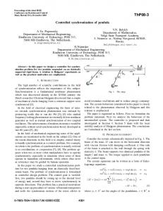
Fig. 1. Example of pin-actuation sequences and mapping to an undirected graph.
ing the one just under the droplet. This electronic method of wettability control creates interfacial tension gradients that move the droplets to the activated electrode. Fluid-handling operations such as droplet merging, splitting, mixing, and dispensing can be executed in a similar manner. For example, mixing can be performed by routing two droplets to the same location and then transporting them together [6]. The digital microfluidic platform particularly offers the additional advantage of flexibility, also referred to as reconfigurability, since fluidic operations can be performed anywhere on the array and the droplets need not follow unidirectional pathways. Droplet routes and operation scheduling are pre-programmed into a microcontroller that drives electrodes in the array. To reduce the number of control pins, several pin-assignment methods [8], [17]–[19] have been proposed to design pinconstrained biochips. In [8], the number of control pins is minimized by using a multi-phase bus for the fluidic pathways. Every nth electrode in an n-phase bus is electrically connected, where n is small number (typically n = 4). Thus, only n control pins are needed for a transport bus, irrespective of the number of electrodes that it contains. An alternative design uses row and column addressing, which is referred to as “cross referencing”. An electrode is connected to two pins, corresponding to a row and a column, respectively [17]. A broadcast-addressing-based design technique for pin-constrained and multi-functional biochips is proposed in [19]. III. S YNCHRONIZATION OF C ONCURRENTLY-I MPLEMENTED F LUIDIC O PERATIONS IN P IN -C ONSTRAINED C HIPS Based on the schedule derived from architectural synthesis [11], a bioassay is implemented by performing several groups of fluidic operations at different time spans. All the fluidic operations within one group are concurrently implemented by applying their corresponding pin-actuation sequences at the same time. A pin-actuation sequence consists of several pin-actuation vectors that are implemented serially. The time-duration for implementing one vector is one clock cycle. Each bit of a vector represents the status of the corresponding pin in the biochip at this clock cycle. The status of a pin can be either “1” (activate), “0” (deactivate) or “don’t-care”. The “don’t-care” status is represented using the symbol “x”. We use the three values “1”, “0”, and “x” to represent a bit in the pin-activation vector. The length of a vector is defined as the number of bits in the vector. The length of each vector in the different sequences is the same; it is equal to the number of control pins in the biochip. Fig. 1(a) shows an example of six pin-actuation sequences, where each sequence consists of six pin-actuation vectors. Each vector in a pin-actuation sequence contains several don’tcare bits, which can be replaced by “1” or “0”. A bit-pair is defined as a pair of two bits that represent the status of the same
pin in two vectors at a given clock cycle. For each bit-pair in two vectors, if either the values of the bit-pair are the same, or the value of one bit in the bit-pair is “x”, we refer to the two vectors as being compatible. Two compatible vectors can be made identical by replacing the don’t-care term in each bit-pair with the value (“0” or “1”) of the other bit. If both bits are “x”, we simply map them both to the same logic value. The two identical vectors can then be merged into one pin-actuation vector. Consider a group of pin-actuation sequences corresponding to a group of concurrently-implemented fluidic operations. For each time-step, if all the vectors are pair-wise compatible, we refer to the sequences in the group as being compatible. Mutuallycompatible sequences can be implemented concurrently, without any conflict in pin actuation. Therefore, these mutuallycompatible sequences in the group can be made identical and merged into one outcome sequence by serially merging all the vectors at the same time-step. If the pin-actuation sequences in a group are not mutually compatible, the merging of these sequences may lead to erroneous assay outcomes. Therefore, we present a two-phase method for fine-grained merging and parallelization of such sequences. In the first phase, we partition these sequences into groups, such that all sequences in a group are pairwise-compatible and can be merged into a single outcome sequence. However, these merged outcome sequences are not mutually compatible. In the second phase, by stalling some vectors in the outcome sequences of Phase 1 for several clock cycles, we can further parallelize these outcome sequences. A vector is stalled for k clock cycles if it is repeated k times, thereby delaying the successor vectors in the sequence. An optimization method is used to minimize the number of vectors in the sequence resulting from Phase 2. IV. M ERGING OF S EQUENCES (P HASE 1) The problem of finding the minimum number of groups can be easily mapped to the clique-partitioning problem from graph theory [4]. We use the example in Fig. 1(a) to illustrate this mapping. Based on the actuation-sequence table, we construct an undirected graph, referred to as pin-actuation graph; see Fig. 1(b). Each node in the graph represents a pin-actuation sequence. There is an edge between a pair of nodes if their corresponding pin-actuation sequences are compatible. Clique partitioning refers to the problem of dividing a set of nodes into non-overlapping subsets, such that the subgraph constructed by each subset is a complete subgraph. A minimal clique partition is one that covers the nodes in the graph with a minimum number of disjoint complete subgraphs. The minimum number of groups of compatible sequences is equivalent to the size of a minimal clique-partition. A minimal clique partition for the example in Fig. 1 is given by {1,3,5}, {2,4,6}. Although the clique partitioning problem is known to be NP-hard [4], heuristics can be used to solve it in an efficient manner. Next we merge all the sequences in a clique to an outcome sequence. For example, for the group {1,3,5}, the outcome sequence “011, 111, 000, 011, 100, 100” is compatible with all the individual sequences. Therefore, we can concurrently execute the operations corresponding to sequences 1, 3, and 5. The group {2,4,6} can be merged into an outcome sequence “110, 011, 100, 011, 011, 100”.
However, the merged sequences are not mutually compatible. Therefore, they cannot be performed concurrently. We next parallelize these non-mutually-compatible sequences, and minimize the number of vectors in the resulting outcome sequence. V. PARALLELIZATION OF S EQUENCES (P HASE 2) In order to parallelize incompatible pin-actuation sequences, we stall some vectors in the sequences for an appropriate number of clock cycles, so as to make all vectors at the same timestep pairwise-compatible. After such fine-grained parallelization, the length of a sequence may be increased since some of its vectors may be stalled for several clock cycles. However, the implementation order of the vectors in each sequence remains the same. In the extended sequences, the vectors at the same time-step are pair-wise compatible. Therefore, these extended sequences are mutually-compatible and they can be merged to form an outcome sequence. Note that at a specific clock cycle, a vector at the previous clock cycle from one sequence can stall only when it is mutually compatible with vectors at current clock cycle from other sequences. Without the above constraint, i.e., vectors at a specific clock cycle are not mutually compatible, the concurrent implementation of these vectors will lead to pinactuation conflicts. However, stalling a vector, which was intended for only one clock cycle in the assay protocol, for several clock cycles will increase the completion time of its corresponding operation; therefore, it increases the completion time for a group of operations that are executed concurrently. Therefore, the length (number of vectors) of the outcome sequence after parallelization must be minimized. A. Parallelization based on an ILP model Assume that N concurrently-implemented pin-actuation sequences need to be parallelized, and let the length of sequence k be Lk . Sequence k includes a series of Lk vectors, namely Vik (ik = 1, 2, . . . , Lk ). A set of vectors is denoted by {Vi1 , Vi2 , . . . , ViN }, where Vik is the ik th vector from sequence k. If vector Vik from sequence k is not compatible with another vector Vil from sequence l, the vectors in a vector set that includes Vik and Vil are not mutually compatible. A vector set is called a compatible vector set only if all the vectors within it are mutually compatible. Let ci1 i2 ...iN be a constant defined as follows: ⎧ ⎨ 1 if the vectors in the set {Vi1 , Vi2 , . . . , ViN } are all mutually compatible ci1 i2 ...iN = ⎩ 0 otherwise For a compatible vector-set, we determine if all vectors in it can be merged to form a vector of the outcome sequence. The parameter ci1 i2 ...iN can be pre-calculated from the given vector sequences. Let xi1 i2 ...iN be a binary variable defined as follows: ⎧ ⎨ 1 if the vectors in the set {Vi1 , Vi2 , . . . , ViN } are merged xi1 i2 ...iN = ⎩ 0 otherwise Our goal is to minimize the number of vectors in the outcome sequence after parallelization. We achieve this goal by minimizing
the number of merged vector sets, where all vectors in a set are mutually compatible. The objective function for the ILP model can therefore be stated as follows: Minimize F =
L1 � L2 �
···
i1 =1 i2 =1
LN �
ci1 i2 ...iN xi1 i2 ...iN .
iN =1
The corresponding operations that are executed concurrently should start and finish at the same time, since the droplets involved in these operations should be maintained at their initial or final locations by avoiding the “floating” status of pins. If an operation does not start while other concurrently-executed operations start, its pin-actuation is not applied and the corresponding control pins are in “floating” status. In this situation, the droplets involved in this operation will not be held on the initial positions and may mix inadvertently with other droplets. Therefore, all vectors in sets {V1 , V1 , . . . , V1 } and {VL1 , VL2 , . . . , VLN } must be mutually compatible, i.e., the conditions c11...1 = 1 and cL1 L2 ...LN = 1 must be satisfied. We add constraints to ensure that all vectors in sets {V1 , V1 , . . . , V1 } and {VL1 , VL2 , . . . , VLN } are merged. The constraints can be represented by the following two equations: (i) c11...1 x11...1 = 1; (ii) cL1 L2 ...LN xL1 L2 ...LN = 1. To perform the N pin-actuation sequences synchronously, each vector in a sequence (e.g., vector Vik in kth sequence) must be executed for at least one clock cycle during the implementation of the outcome sequence after parallelization. Therefore, vector Vik must be in at least one compatible vector-set, which must be merged to form a vector in the outcome sequence. This constraint can be written as: ∀ ik (1 ≤ ik ≤ Lk , 1 ≤ k ≤ N ), L1 � i1 =1
Lk−1
···
�
Lk+1
�
ik−1 =1 ik+1 =1
···
LN �
ci1 ...iN xi1 ...iN ≥ 1.
iN =1
Consider a compatible vector-set vs1 : {Vi1 , . . . , Vik , . . . , Vil , . . . , ViN }, where 1 ≤ ik ≤ Lk , 1 ≤ il ≤ Ll and 1 ≤ k, l ≤ N , which has already been merged. That is to say, xi1 ...ik ...il ...iN = 1. If two vectors Vjk and Vjl in another compatible vector-set vs2 {Vj1 , . . . , Vjk , . . . , Vjl , . . . , VjN } satisfy the relationship “1 ≤ jk < ik ” and “il < jl ≤ Ll ”, vs2 must not be merged. In other words, xj1 ...jk ...jl ...jN must be equal to 0. The violation of the above constraint will lead to timing problems when we implement N sequences concurrently. For instance, suppose the compatible vector-set vs2 can be merged, i.e., xj1 ...jk ...jl ...jN = 1. Under this assumption, two vectors obtained by merging both vector sets vs1 and vs2 will be implemented in the outcome sequence serially. However, on one hand, if the vector obtained by merging vs1 is implemented before the vector obtained by merging vs2 , the prerequisite “1 ≤ jk < ik ” is violated. On the other hand, implementing the vector obtained by merging vs2 before the vector obtained by merging vs1 will violate the prerequisite “il < jl ≤ Ll ”. Therefore, only one compatible vector-set, either vs1 or vs2 , can be merged. We formulate this constraint as follows: ci1 ...ik ...il ...iN xi1 ...ik ...il ...iN + cj1 ...jk ...jl ...jN xj1 ...jk ...jl ...jN ≤ 1. The complete ILP model is as follows: Minimize F, subject to (1) c11...1 x11...1 = 1.
TABLE I E XAMPLE OF PIN - ACTUATION SEQUENCES . Sequence. no. Actuation sequence
1 1xx1 1x10 0x11 x0x1 00xx
2 x11x x01x 1x1x 0xxx
3 1x1x xx11 x01x x01x
(2) cL1 L2 ...LN xL1 L2 ...LN = 1. (3) ∀ ik (1 ≤ ik ≤ Lk , 1 ≤ k ≤ N ), L1 � i1 =1
Lk−1
···
�
Lk+1
�
ik−1 =1 ik+1 =1
···
LN �
ci1 ...iN xi1 ...iN ≥ 1.
iN =1
(4) if 1 ≤ jk < ik and il < jl ≤ Ll , ci1 ...ik ...il ...iN xi1 ...ik ...il ...iN + cj1 ...jk ...jl ...jN xj1 ...jk ...jl ...jN ≤ 1. We use an example in Table I to illustrate the parallelization of pin-actuation sequences for N = 3. There are 5 × 4 × 4 vector sets, i.e., 80 vector sets. We calculate ci1 i2 i3 (1 ≤ i1 ≤ 5, 1 ≤ i2 ≤ 4, 1 ≤ i3 ≤ 4) in advance before constructing the ILP model. For example, all vectors “1xx1”, “x11x”, and “1x1x” in the vector set {V1 , V1 , V1 } are mutually compatible, therefore c111 = 1. The binary variable xi1 i2 i3 is 1 if vectors Vi1 , Vi2 , and Vi3 are merged; otherwise it is 0. The objective function is as follows: �4 �4 �5 Minimize F = i1 =1 i2 =1 i3 =1 ci1 i2 i3 xi1 i2 i3 . The constraints that all vectors in sets {V1 , V1 , V1 } and {V5 , V4 , V4 } must be mutually compatible are: (i) c111 x111 = 1; (ii) c544 x544 = 1. The constraint that each vector in a sequence (e.g., the 2nd vector in the 2nd sequence) must be in at least one merged vector-set must also be�satisfied. �4 For example, for the 5 2nd vector in Seq. 2, we have i1 =1 i3 =1 ci1 2i3 xi1 2i3 ≥ 1. We next consider the constraints for avoiding timing problems. For example, the compatible vector set {Vi1 , Vi2 , Vi3 } = {V4 , V2 , V1 }, and compatible vector set {Vj1 , Vj2 , Vj3 } = {V1 , V2 , V3 }, satisfy the relationship “j1 < i1 ” and “i3 < j3 ”. Suppose the two compatible vector-sets can be merged at the same time. Two vectors obtained by merging both vector sets will be implemented in the outcome sequence serially. If the vector obtained by merging {V4 , V2 , V1 } is implemented before the vector obtained by merging {V1 , V2 , V3 }, the 4th vector from Seq. 1 is implemented before the 1st vector from Seq. 1, which violates the order of vectors in Seq. 1. On the other hand, if we implement the vector obtained by merging {V1 , V2 , V3 } before the vector obtained by merging {V4 , V2 , V1 }, the 3rd vector from Seq. 3 is implemented before the 1st vector from Seq. 3, which violates the order of vectors in Seq. 3. Therefore, only one compatible vector-set, either {V1 , V2 , V3 } or {V4 , V2 , V1 }, can be merged. This constraint is written as follows: c123 x123 + c421 x421 ≤ 1. The results obtained by solving the ILP model are shown in Table II. If xi1 i2 i3 = 1, a group of mutually compatible vectors Vi1 , Vi2 , and Vi3 are merged into a vector of the outcome sequence (Outcome Seq.). Note that some vectors are stalled for several clock cycles to facilitate parallelization. For example, the first vectors in Seq. 2 and Seq. 3 are stalled for two clock cycles
TABLE II R ESULT OBTAINED FROM ILP MODEL . Clock cycle 1 2 3 4 5
xi1 i2 i3 x111 = 1 x211 = 1 x322 = 1 x433 = 1 x544 = 1
Seq. 1 1xx1 1x10 0x11 x0x1 00xx
Sequence no. Seq. 2 Seq. 3 Outcome Seq. x11x 1x1x 1111 x11x 1x1x 1110 x01x xx11 0011 1x1x x01x 1011 0xxx x01x 001x
1: Check whether vectors in set {V1 , V1 , . . . , V1 } are mutually compatible and merge them together to form the first vector in outcome sequence; 2: for j = 1 to ROU N D do 3: Reset all the pointers to second vectors of sequences; 4: while at least one vector has not been parallelized do 5: Check the location of each pointer, e.g., pointer of the kth pinactuation sequence (1 ≤ k ≤ N ) locates at Vik +1 ; 6: Randomly select a compatible vector-set from vector-sets {Vi1 or Vi1 +1 , Vi2 or Vi2 +1 , . . . , Vik or Vik +1 , . . . , ViN or ViN +1 } except the vector-set {Vi1 , Vi2 , . . . , Vik , . . . , ViN }; 7: if a compatible vector-set exists then 8: Merge all the vectors within it to form a vector in the outcome sequence; Adjust the pointer for each sequence; 9: else 10: break; 11: end if 12: end while 13: if finish parallelization of N pin-actuation sequences then break; 14: end if 15: end for 16: Output the result of parallelization: success or failure. Fig. 2.
Pseudocode to parallelize N pin-actuation sequences.
each. The experiments were performed on a 2.0 GHz INTEL Core2 Dual processor, with 1 GB of memory. The CPU time needed for solving the above ILP model is only 0.1s for this example. Even though the above ILP model is useful for problem understanding and for deriving lower bounds on sequence length via LP-relaxation, it suffers from the drawback that it may be too complex for problem instances involving more than a few pinactuation sequences or vectors. Therefore, we develop a heuristic method to parallelize N sequences within reasonable CPU time. B. Parallelization based on a heuristic method For each sequence, we assign a pointer to the vector whose successor vectors (including itself) have not been parallelized, while all its predecessor vectors have been parallelized with vectors from other sequences into vectors of the outcome sequence. At first, each pointer is at the first vector of each sequence. We check whether the first vectors in all the sequences, i.e., the vector-set {V1 , V1 , . . . , V1 } are mutually compatible and merge them together to form the first vector in outcome sequence. Next, all pointers independently move to the 2nd vectors of all the sequences, indicating that the 2nd vectors and their successor vectors in the sequences have not been parallelized. Assume that for the kth pin-actuation sequence (1 ≤ k ≤ N ), vectors V1 , V2 , . . . , Vik have been parallelized with vectors from other sequences into vectors of the outcome sequence, while vectors Vik +1 , Vik +2 , . . . , VLk have not yet been parallelized. For all N sequences, all vectors in vector-set {Vi1 , Vi2 , . . . , Vik , . . . , ViN } are mutually compatible and have been merged to form a vector in the outcome sequence. Currently the pointer of the kth
Fig. 3.
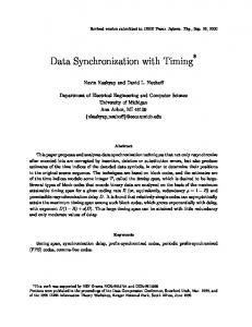
Fabricated biochip used for the n-plex assay experiment.
pin-actuation sequence (1 ≤ k ≤ N ) is at Vik +1 . We attempt to find a compatible vector-set within vector-sets {Vi1 or Vi1 +1 , Vi2 or Vi2 +1 , . . . , Vik or Vik +1 , . . . , ViN or ViN +1 }, except the vector-set {Vi1 , Vi2 , . . . , Vik , . . . , ViN }. If a compatible vectorset exists, e.g., all the vectors in vector-set {Vi1 +1 , Vi2 +1 , . . . , Vik +1 , . . . , ViN +1 } are mutually compatible, we can merge these vectors together to form a vector in the outcome sequence. If multiple compatible vector-sets exist, we randomly select one set and merge all the vectors within it. For the kth pin-actuation sequence (1 ≤ k ≤ N ), if Vik +1 is in the selected vector-set, it is merged with vectors from other sequences to form a vector in the outcome sequence, and the kth pointer is moved to the immediate successor vector Vik +2 . However, if Vik is with the selected vector-set, it is merged with vectors from other sequences. In this case, the kth pointer remains at the vector Vik +1 , since Vik +1 has not been parallelized. The above process is repeated until all the pointers reach the end of the sequences. However, if no compatible vector-set exists, it means that the parallelization of N pin-actuation sequences cannot proceed any more. In this case, we reset all the pointers to the second vectors of sequences, thereby restarting the parallelization process. After multiple rounds, if there is still no compatible vector-set at a specific clock cycle, we conclude that the heuristic method has failed to parallelize the sequences. This aspect of the heuristic method is a drawback compared to the ILP model. The pseudocode for the heuristic method is shown in Fig. 2, where ROU N D is a user defined parameter. The worstcase time complexity of the heuristic method for N pinactuation sequences with maximum sequence length Lmax is O(ROU N D×N ×Lmax ). VI. E XPERIMENTAL R ESULTS The n-plex bioassay is a typical example of a multiplexed and concurrent bioassay. In this assay, a sample is analyzed for n different analytes. Sample droplets are mixed with n different reagents, and the mixed product droplets are routed to a detection site. The signal transduction for quantifying the n droplets is based on an optical signal from each droplet. An optical detector such as a photodiode can be used to analyze the product droplets of the n-plex bioassay. As an example of an n-plex assay, we demonstrated a 3-plex assay for the diagnosis of acute myocardial infarction (AMI) [10] on a fabricated digital microfluidic platform; see Fig. 3. The fabricated chip is a pin-constrained design that consists of over 1000 electrodes and 64 control pins [10]. The platform consists of three regions: dispensing region, reaction region, and detection
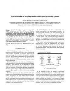
region. Note that the electrodes in different regions are connected to separate sets of control pins. In the dispensing region, there are 20 reservoirs for high-throughput processing, with 8 reservoirs for sample solutions and 12 reservoirs for reagent solutions. The sample (reagent) reservoirs are accessed using vertical (horizontal) transport buses. Each reagent reservoir intersects with these vertical transport buses using a horizontal transport bus. In the reaction region located in the middle of the platform, there are 12 horizontally-placed reactors where the reagent and sample droplets are mixed. Each reactor is connected to a horizontal transport bus from the dispensing region. The droplets are then routed through a multi-phase transporter in the detection region. For the 3-plex assay, an example of human physiological fluids, i.e., serum, is sampled and dispensed to the digital microfluidic biochip. Three assays, namely troponin-I, myoglobin, and creatine kinase-MB (CK-MB) measurements are performed on the physiological fluid. The 3-plex assay includes three stages: dispensing and routing, reaction, and detection, which are performed in the dispensing region, reaction region, and detection region, respectively. The 3-plex assay is implemented by serially performing groups of fluidic operations at different time spans. All the fluidic operations within one group are concurrently implemented by applying their corresponding pin-actuation sequences at the same time. We synchronize these operations by merging and parallelizing their corresponding pin-actuation sequences, in order to avoid pin-actuation conflicts. For example, during a specific duration in the detection stage, seven operations, namely dispensing a substrate droplet (denoted as SB) from the substrate reservoir, dispensing a wash droplet (denoted as W A) from the wash reservoir, transporting two product droplets D1 and D2 , as well as transporting three wash droplets W1 , W2 , W3 along the transport bus, are implemented concurrently. The details about their corresponding pin-actuation sequences are described in Table III. We next synchronize the operations in Table III by merging and parallelizing their corresponding pin-actuation sequences. We construct a pin-actuation graph based on the sequences in Table III; see Fig. 4(a). Note that a group of nodes corresponding to sequences 3-7 are pair-wise compatible, since each of them is the sequence corresponding to the operation that transports a droplet with 8-electrode spacing. A minimal clique partition for the example in Fig. 4(a) is given by {1}, {2}, {3, 4, 5, 6, 7}. We merge all the sequences in the third partition. The outcome sequence obtained by merging sequences in the partition {3, 4, 5, 6, 7} is the same as Seq. 3. We next parallelize the three sequences, namely Seq. 1-3, using both the ILP model and the heuristic method. The CPU times for solving this ILP model is 26.12 s. We construct a table based on the solution obtained using the ILP model, as shown in Fig. 4(b). If xi1 i2 i3 = 1, a group of vectors Vi1 , Vi2 , and Vi3 are pair-wise compatible at the same time-step, therefore they are listed in the same row. Note that some vectors are stalled for several clock cycles to facilitate the parallelization. The vectors in each row are merged to form a vector of the outcome sequence. The outcome sequence is generated by merging all the vectors in the same row into an outcome vector serially from clock cycle 1 to 9. The length of the outcome sequence is minimized to 9 clock cycles,
TABLE III P IN - ACTUATION SEQUENCES CORRESPONDING TO OPERATIONS IN DETECTION STAGE . Clock cycle 1 2 3 4 5 6 7 8 9
1
Seq. 1 (W A) V11 V12 V13 V14 V15 V16
Seq. 2 (SB) V21 V22 V23 V24 V25 V26 V27
Sequence. no. (operation) Seq. 3 (D1 ) Seq. 4 (D2 ) Seq. 5 (W1 ) V31 V41 V51 V32 V42 V52 V33 V43 V53 V34 V44 V54 V35 V45 V55 V36 V46 V56 V37 V47 V57 V38 V48 V58 V39 V49 V59
2 3
4
5
6
7 (a)
(b)
Fig. 4. Merging and parallelization of pin-actuation sequences in Table III: (a) pin-actuation graph; (b) result of ILP model.
Fig. 5. Comparison of the completion time of the proposed optimization method with the baseline schedule for the 3-plex assay.
equal to the length of Seq. 3. We next use the heuristic method to parallelize Seq. 1-3. The CPU time is only 0.37 s, which is 1.5% of the CPU time for ILP. The length of the outcome sequence is 10 clock cycles, one clock cycle larger than that for the ILP model. We next compare the completion time of the 3-plex bioassay for the ILP model, the heuristic method, and a baseline method; see Fig. 5. For the baseline method, we do not consider the merging and parallelization of a group of concurrentlyimplemented fluidic operations at each time span. Since the pin-actuation sequences of those operations are not mutually compatible, they have to be implemented serially. Our results show a significant reduction (nearly one-third) in the time-toresult for the 3-plex bioassay. VII. C ONCLUSIONS We have presented a two-phase optimization method to synchronize the fluidic operations that are executed concurrently
Seq. 6 (W2 ) V61 V62 V63 V64 V65 V66 V67 V68 V69
Seq. 7 (W3 ) V71 V72 V73 V74 V75 V76 V77 V78 V79
in pin-constrained biochips, in order to avoid pin-actuation conflicts. The optimization method merges the corresponding pin-actuation sequences based on clique partitioning in graphs in the first phase, and parallelizes the non-mutually-compatible pin-actuation sequences in the second phase. The optimization method has also minimized the length of the outcome sequence after the synchronization. A 3-plex bioassay has been implemented on a fabricated pin-constrained biochip to demonstrate the effectiveness of the proposed optimization method. R EFERENCES [1] R. B. Fair et al., “Chemical and biological applications of digitalmicrofluidic devices”, IEEE Design & Test of Computers, vol. 24, 2007. [2] J. Gong et al., “Portable digital microfluidics platform with active but disposable lab-on-chip,” Proc. IEEE MEMS, pp. 355-358, 2004. [3] I. B.-Nad et al., “Digital microfluidics for cell-based assays”, Lab on a Chip, vol. 8, pp. 519-526, 2008. [4] J. L. Gross and J. Yellen, Graph Theory and Its Applications, CRC Press, FL, 1999. [5] P. Paik et al., “Coplanar digital microfluidics using standard printed circuit board processes,” MicroTAS, 2005. [6] P. Paik et al., “Electrowetting-based droplet mixers for microfluidic systems”, Lab on a Chip, vol. 3, pp. 28-33, 2003. [7] K. Gernaey et al., “Fast and sensitive acute toxicity detection with an enrichment nitrifying culture”, Water Environment Research, vol. 69, pp. 1163-1169, 1997. [8] V. Srinivasan et al., “An integrated digital microfluidic lab-on-a-chip for clinical diagnostics on human physiological fluids”, Lab on a Chip, vol. 4, pp. 310-315, 2004. [9] R. Sista et al., “Heterogeneous immunoassays using magnetic beads on a digital microfluidic platform”, Lab on a Chip, vol. 8, pp. 2188-2196, 2008. [10] R. Sista et al., “Development of a digital microfluidic platform for point of care testing”, Lab on a Chip, vol. 8, pp. 2091-2104, 2008. [11] F. Su and K. Chakrabarty, “High-level synthesis of digital microfluidic biochips”, ACM J. Emerging Tech. Comp. Sys., vol. 3, 2008. [12] F. Su and K. Chakrabarty, “Unified high-level synthesis and module placement for defect-tolerant microfluidic biochips”, Proc. DAC, 2005. [13] F. Su et al., “Droplet routing in the synthesis of digital microfluidic biochips”, Proc. DATE, pp. 323-328, 2006. [14] P.-H. Yuh et al., “Placement of defect-tolerant digital microfluidic biochips using the T-tree formulation”, ACM J. Emerging Tech. Computing Sys., vol. 3, pp. 13.1-13.32, 2007. [15] P.-H. Yuh et al., “BioRoute: A network flow based routing algorithm for digital microfluidic biochips”, Proc. ICCAD, pp. 752-757, 2007. [16] M. Cho and D. Z. Pan, “A high-performance droplet router for digital microfluidic biochips”, Int. Symp. Phy. Design, pp. 200-206, 2008. [17] S.-K. Fan et al., “Manipulation of multiple droplets on N × M grid by cross-reference EWOD driving scheme and pressure-contact packaging”, Proc. Int. Conf. MEMS, pp. 694-697, 2003. [18] T. Xu et al., “Automated design of pin-constrained digital microfluidic biochips under droplet-interference constraints”, ACM J. Emerging Tech. in Computing Sys., vol. 3, article 14, 2007. [19] T. Xu and K. Chakrabarty, “Broadcast electrode-addressing for pinconstrained multi-functional digital microfluidic biochips”, Proc. DAC, pp. 173-178, 2008.