Synchronization of Multiple Autonomic Control. Loops: Application to Cloud Computing. Frederico Alvares de Oliveira Jr., Remi Sharrock, and Thomas Ledoux.
Synchronization of Multiple Autonomic Control Loops: Application to Cloud Computing Frederico Alvares de Oliveira Jr., Remi Sharrock, and Thomas Ledoux Ascola Research Group (Mines Nantes-INRIA, LINA) Ecole des Mines de Nantes, 4, rue Alfred Kastler, 44307 Nantes, France {frederico.alvares,remi.sharrock,thomas.ledoux}@mines-nantes.fr
Abstract. Over the past years, Autonomic Computing has become very popular, especially in scenarios of Cloud Computing, where there might be several autonomic loops aiming at turning each layer of the cloud stack more autonomous, adaptable and aware of the runtime environment. Nevertheless, due to conflicting objectives, non-synchronized autonomic loops may lead to global inconsistent states. For instance, in order to maintain its Quality of Service, an application provider might request more and more resources while the infrastructure provider, due to power shortage may be forced to reduce the resource provisioning. In this paper, we propose a generic model to deal with the synchronization and coordination of autonomic loops and how it can be applied in the context of Cloud Computing. We present some simulation results to show the scalability and feasibility of our proposal. Keywords: Cloud Computing; Autonomic Computing; Autonomic Loop Synchronization; Coordination
1
Introduction
The necessity of modern software systems to be more responsive and autonomous to environment changes is one of the main reasons for the popularization of Autonomic Computing [7]. Cloud Computing is one of the most expressive examples of this great adoption. Indeed, the flexibility inherent to cloud services along with the high variability of demand for those services have recently contributed to the large adoption of Autonomic Computing in Cloud-based systems [1]. In point of fact, from the application provider perspective, Autonomic Computing makes application capable of reacting to a highly variable workload by dynamically adjusting the amount of resources needed to be executed while keeping its Quality of Service (QoS) [11]. From the infrastructure provider point of view, it also makes the infrastructure capable of rapidly reacting to environment changes (e.g. increase/decrease of physical resource usage) by optimizing the allocation of resources and thereby reduce the costs related to energy consumption [4]. However, getting several control loops working on common or inter-dependent managed elements is not a trivial task [6]. For example, in order to cope with
2
Frederico Alvares de Oliveira Jr., Remi Sharrock, and Thomas Ledoux
a high demand, Application Providers may request more and more computing resources to the Infrastructure Provider. At the same time, the Infrastructure Provider may turn off part of its physical infrastructure to meet power constraints. Therefore, dealing with multiple control loops with conflicting objectives (performance vs power) may lead to inconsistent global results. Besides, inter-control loop interactions must be synchronised and coordinated for the various phases of adaptations [13]. This paper proposes a generic model for synchronization and coordination of control loops. We have studied a communication model for several control loops and proposed a coordination protocol based on interloop events and actions. To allow safe interactions, we propose a shared knowledge-based synchronization pattern. That way, decisions taken by one control loop may take into consideration some information provided by other control loops. This model is applied to a Cloud Computing scenario in which several self-adaptive applications interact with a common self-adaptive infrastructure. The objective at the application level is to manage the runtime context to minimize costs while maximizing the QoS, whereas at the infrastructure level, the objective is to manage the context to optimize the utilization rate. The feasibility and scalability of this approach is evaluated via simulation-based experiments on the Cloud Computing scenario. The remainder of this paper is organized as follows: Section 2 presents our contribution by describing a generic model for synchronization and coordination of multiple control loops. In Section 3, this model is instantiated in a scenario of Cloud Computing. Section 4 presents the evaluation of our approach. Section 5 presents a brief discussion about the most relevant works related to this paper. Finally, Section 6 concludes the paper and provides some future research directions.
2
A multiple control loops architecture model
Autonomic computing [7] aims at providing self-management capabilities to systems. The managed system is monitored through sensors, and an analysis of this information is used, in combination with knowledge about the system, to plan and execute reconfigurations through actuators. Classically, an autonomic manager internal structure is implemented by a MAPE-K (Monitor-Analyze-PlanExecute phases over a Knowledge base) control loop [5]. Bottom-up interactions between the managed system and the autonomic manager are realized via events whereas top-down interactions via actions. Our approach aims to provide synchronized and coordinated control loops by introducing a synchronization of the shared knowledge and a coordination protocol. 2.1
A model of autonomic behavior
We make a distinction between three kinds of control loops:
Synchronization of Multiple Autonomic Control Loops
3
– Independent: this type of control loop is completely independent from the others. The source of the received events is always the managed system and the actions are executed only on the considered system. There is no communication between control loops and the knowledge is entirely internal (private to the control loop). – Coordinated: this type of control loop communicates with the others. Events may come from other control loops and actions may notify other control loops. A business-specific protocol defines a way for the control loops to communicate. In this case, we do not consider the sharing of information between control loops but only simple asynchronous communication. – Synchronized: this type of control loop synchronizes with the others in order to share some information for a collective activity. Access to this shared information may lead to concurrency and consistency problems. In our Cloud Computing scenario, we consider coordinated and synchronized control loops and demonstrate both situations. A public and private knowledge model. In the case of synchronized control loops, regarding the sharing of information we separate the knowledge base in two parts: the private knowledge that stores the internal information needed by the internal control loop phases and the public knowledge shared among other control loops. The public knowledge base may have to be synchronized if the actions executed by the control loops require to modify the information (directly or indirectly). Indeed, the simultaneous actions of multiple control loops may require to change the public knowledge at the same time (concurrency problem) and may lead to non-logical global results (consistency problem). In our approach, we consider that the owner of the public knowledge is the only one able to modify it directly, which limits the concurrency problem. Actions
On the Managed System
Events
Intraloop
Change Public Knowledge
Interloop
Invoke Handle
Endogenous
Exogenous
Interloop
Public Knowlege Changed
Fig. 1. Actions and Events hierarchy
Actions. In order to clarify the interactions between several control loops, it is important to differentiate actions and events that are part of the managed system and those part of the multi control loop system model. Figure 1 introduces a hierarchy of the different types of events and actions. Actions can be executed on the considered managed system, can start a phase within the control loop (intraloop) or notify another control loop (interloop). The actions on the managed system and the interloop actions are always executed by the execution phase of the control loop. The intraloop actions are
4
Frederico Alvares de Oliveira Jr., Remi Sharrock, and Thomas Ledoux
either executed by the monitoring phase to launch the analysis phase or the execution phase (M → A or M → E), by the analysis phase to launch the planning phase (A → P ) or by the planning phase to launch the execution phase (P → E). An interloop action may notify another control loop as if it was asking for a service and waiting for the response. In this case, the planning phase creates a handler that contains all the other actions that have to be executed in response to this interloop action. This interloop action is therefore a notify action that creates an interloop event for the target control loop. Intraloop actions are either Change Public Knowledge or Invoke Handler actions. In our approach, we consider that these actions do not need analysis or planning phases to be launched, which corresponds to the M → E case. Events. In Figure 1, we differentiate endogenous and exogenous events. The source of endogenous events is always the considered managed system. The source of exogenous events is another control loop. For the exogenous events, we consider the difference between the interloop events - created by the interloop action - and the Public Knowledge Changed - created by the Change Public Knowledge action. In order for the control loops to send and receive events, we consider that they already implement the publish/subscribe paradigm. The control loops using some public knowledge of other control loops automatically subscribe to the Public Knowledge Changed events. 2.2
Control loop synchronization and coordination
Token protocol for synchronizing the public knowledge. The public knowledge is divided into one non-critical section and some critical sections. One control loop may access multiple non-critical sections but one and only one critical section at a time in order to avoid deadlocks. To synchronize the public knowledge we introduce a simple token protocol. Each critical section is associated with one token. As for transactions in databases, this synchronization protocol ensures that only one control loop can access a critical section. To access the critical section, a control loop has to get the corresponding token. To get the token, a control loop can either ask explicitly for the token with a TOKEN REQUEST message (active token request) or can receive the token from another control loop with a TOKEN TRANSFER message (passive token reception). Whenever a control loop does not need the token anymore it releases it with a TOKEN RELEASE message. Whenever a token is requested, the requester has to wait for a TOKEN ACQUIRED message. Each control loop having a public knowledge with critical sections implements a token manager which is in charge of managing the token protocol. Control loop coordination protocol. Considering the coordinated case with multiple control loops, we take into consideration what we call the collaboration
Synchronization of Multiple Autonomic Control Loops
5
problem where two control loops have to communicate in order to accomplish a global activity together. Indeed, the execution phase of one control loop may ask another control loop a service and wait for the result in return. To do this, the first control loop triggers an interloop event that starts the second control loop. As for the ”future objects” in distributed concurrency problems [2], the first control loop creates at the same time a handler containing all the actions that need to be executed after the service is terminated. The interloop event is, as always, detected by the monitoring phase of the second control loop. Once the service is terminated, another interloop event is sent back to the caller control loop. Parts of the results may be transferred using the public knowledge base, to do this, the interloop events may be coupled with token transfer messages. Timing the control loops. All the control loops are evolving in a dynamic environment where multiple events may occur simultaneously. The arrival rate of these events may vary from one control loop to another and are usually stored in a waiting queue. In order to manage the arrival of these events, the monitoring phase of each control loop has a scheduling process. This scheduler may implement different policies, some of them may take into account the events priorities. In our approach and for the sake of simplicity, we consider a FIFO (First-In First-Out) scheduling policy without priorities for endogenous events, and consider the interloop events that invoke handlers with the highest priority. Indeed, handlers are containing actions that have to be executed in response to a service request and need to be treated in priority in order for the source event to be considered as treated as soon as possible. Therefore, one event is considered to be treated only if the entire control loop is finished, including the possible handlers. In order to formalize the timings, we introduce these notations: Tij = Tlock + µji
(1)
= + ρi (modif ) ∗ (TijP + TijE ) 0 + ρi (interloop) ∗ (Tij0 + TijEhandler )
(2)
µji TijE
=
TijEactions
TijA
(3)
Tij : Time to treat event i for control loop j Tlock : Waiting time for the token to be acquired µji : service time on control loop j for event i ρi (modif ) : probability to start a planning and execution phase (modification of the system required) TijA : Analysis phase time for event i and control loop j TijP : Planning phase time for event i and control loop j TijE : Execution phase time for event i and control loop j TijEactions : First part of the execution phase time for event i and control loop j ρi (interloop) : Probability to ask another control loop a service with an interloop event 0 Tij0 : Time for the other control loop j 0 to treat the interloop event i0 jEhandlers Ti : Time to execute the handlers for event i and control loop j
Frederico Alvares de Oliveira Jr., Remi Sharrock, and Thomas Ledoux
M-1
A-1
P-1
TOKEN
TA INTRA Event 1 treated
T11A
Tlock
E-1
M-2
TReq
endogenous event 1
endogenous event 2
1
TRel
TA
TReq
Tlock
endogenous event 1 TReq
Tlock
6
A-2 P-2 E-2
2
TRel
TA
T21A
INTRA
1
INTRA
T21Eactions
T21P
INTRA
endogenous event 3
exogenous event 2
INTER TT
waiting queue
T22
2
A-2 P-2 E-2
TRel
exogenous event 4 INTRA Invoke Handler
Event 2 treated
T21Ehandlers
INTER
Treq = Token request Trel = Token release TA = Token Aquired TT = Token Transfer INTRA = Intraloop action INTER = Interloop action/event
Fig. 2. Control loops coordination and token synchronization protocols and timings
Figure 2 shows how two control loops would use the token synchronization protocol and the coordination protocol with a sequence diagram. The M-1 to E-1 vertical lines are the phases of the first control loop and we show only the monitoring phase of the second control loop M-2. The TOKEN line shows which control loop has the token to access one critical section of the public knowledge of the second control loop. As we can see the monitoring phases are continuously listening for events. A first endogenous event arrives for control loops 1 and 2. The control loop 1 acquires the token (TReq and TA), launches the analysis (INTRA) and releases the token straight after the event is treated (TRel). The same goes for control loop 2 which acquires the token as soon as it is released by control loop 1. A second endogenous event is treated by control loop 1 which requires a coordination between control loop 1 and control loop 2. First, the loop 1 acquires the token and launches the analysis A-1, the planning P-1 and the execution
Synchronization of Multiple Autonomic Control Loops
7
phases E-1. As we can see control loop 1 sends an exogenous event to control loop 2 (first INTER, exogenous event 2) along with the token (TT). This allows control loop 2 to eventually modify its knowledge. As soon as control loop 2 finishes to treat this event, it sends back an exogenous event to control loop 1 (second INTER, exogenous event 4), which allows control loop 1 to execute the handler (INTRA invoke handler) and to finish treating the event 2.
3
Cloud Computing Scenario
The objective of this section is to instantiate the generic model presented in Section 2 in the context of Cloud Computing. First, we give some definitions and assumptions for this scenario. Then, we present a multi-control loop architecture along with its possible events, actions and public knowledge. 3.1
Definitions and Assumptions
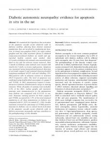
The Cloud Computing architecture is typically defined as a stack of several inter-dependent systems, in which systems on lower layer are service providers to subsystems on upper layers. Our scenario consists of two types of inter-dependent managed systems: Applications and Infrastructure. An application is defined as a set of components. Each component offers a set of services, which, in turn, might depend on a set of references to services offered by other components. Services are bound to references through bindings. The application can operate in different architectural configurations, which are determined by the subset of components used and how they are linked to each other. In other words, one configuration is composed of a set of bindings. In addition, each configuration has also its QoS defined in terms of performance and an application-specific QoS. The former corresponds to the application responsiveness when dealing with a given number of simultaneous requests λ (requests/sec), whereas the latter is a quality degree specific to the application domain. The infrastructure consists of a set of Physical Machines (PMs), whose computing resources (CPU and RAM) are made available by means of Virtual Machines (VMs). There might be one or several classes of VM, each one with a different CPU or RAM capacity. Application Providers are charged an amount per hour for using a VM instance. They may deploy the same component on one or more VMs, that is, for each component there might be one or several instances. Finally, the Infrastructure Provider may give a limited number of discounts for each VM classes in order to attract Application Providers so as to occupy portions of resources that are not being utilized and hence improve their utilization rate. Figure 3 illustrates two cloud applications hosted by the same infrastructure. Application 1 is composed of 4 components and Application 2 is composed of 3 components. The dotted lines express a potential bind between components, whereas the solid lines mean a binding of the current configuration. For application 1, there are two possible configurations ({c1 , c2 , c3 } and {c1 , c4 , c3 }). For application 2, there are also two possible configurations: {c1 , c2 } and {c1 , c3 }.
8
Frederico Alvares de Oliveira Jr., Remi Sharrock, and Thomas Ledoux
The infrastructure is composed of 3 PMs and offers computing resources through three different kinds of VMs (small, medium and large). There are 7 VMs instances to host all the components of both applications. It should be noticed that there are two instances for components c2 (application 1) and c1 (application 2), that is, there are two VMs allocated to each component. That way, components may scale up and down according to the application demand. 3.2
Application1
Application2
c4 c1
c3 c3
c1
c2
VM1
VM2 PM1
c2
VM3
VM4 PM2
VM5
VM6
VM7
PM3
Fig. 3. Cloud Computing Scenario.
Multi-control loop architecture
This scenario comprises several coordinated control loops: one at the infrastructure level, namely the infrastructure manager (IM) and one per-application at application level, namely application manager (AM), as shown in Figure 4. AMs control loops aim at minimizing the amount of VMs needed to keep the level of QoS as high as possible. Furthermore, AMs are able to adapt their application’s architectural configuration in order to cope with resource restriction imposed by the IM. More precisely, AMs monitor/listen for events that come either from the application itself or from the IM; analyze whether or not it is necessary to reconfigure the application by considering the execution context (e.g. the workload, the current application configuration, the current mapping of components to VMs, etc.); elaborate a reconfiguration plan; and execute actions corresponding to the reconfiguration plan. Regarding the IM, apart from dealing with requests sent by AMs, its objective is to optimize the placement of these VMs on PMs so that it is possible to reduce the number of PMs powered on and consequently reduce the energy consumption. To this end, the IM monitors/listens for events that come either from the infrastructure itself (e.g. PMs Utilization) or from the AMs; analyze whether or not it is necessary to replace or to change its current configuration by considering the execution context (e.g. the current mapping VMs to PMs); plan and execute the reconfiguration. As previously mentioned, multiple control loops might have conflicting objectives. Particularly in this scenario, while the IM looks forward to allocate all VMs in the fewest possible number of PMs (due to energy constraints reasons), some AMs may request more VMs in order to cope with an increase in the demand. In this context, we can apply the coordination and synchronization protocols presented in Section 2. The coordination protocol defines a set of messages exchanged by control loops that transformed into actions and events and used for instance to inform AMs about energy shortage at the infrastructure level. The synchronization protocol defines a set of public knowledge (critical) sections that are used for all control loops. For instance, the IM can change the
Synchronization of Multiple Autonomic Control Loops
9
VMs renting fees by putting some VMs on sale. The shared knowledge is used by AMs to take into consideration those changes in order to take better decisions.
Endogenous Event
App1
App2
...
Appn
Action on the Managed System Action on the Managed System Public Knowledge Changed
Invoke Handler
Public Knowledge
Interloop Action / Event Invoke Handler
Change Public Knowledge
Endogenous Event
Infrastructure
Action on the Managed System
Endogenous Event Interloop Event Interloop Action Change Public Knowledge Action Public Knowledge Changed Event Invoke Handler Autonomic Loop
Fig. 4. Multi-control loop Architecture for the Cloud Computing Scenario.
Application Manager Events and Actions. Workload Increased/Decreased are endogenous events corresponding to the percentage of the workload increase/decrease within a pre-defined amount of time. It triggers the analysis phase to determine whether or not it is necessary to request or release resources (VM). The result of this process is translated into a Request VMs interloop action (Figure 5 (a)) or Stop and Unbind Component actions on the application (managed system), followed by a Release VMs interloop (Figure 5 (b)). It is important to notice that in this scenario the public knowledge resides at infrastructure level and it corresponds to the VMs renting fees. Hence, Renting Fees Changed is a Public Knowledge Changed event that happen when the VM Renting Fees are changed (e.g. new VMs with discount available). This kind of event triggers the analysis phase that may result in a Request VMs action (scale up) (Figure 5 (c)). Scale Down is an interloop (exogenous) event whose objective is to notify the AM (from the IM) that it should meet some constraints on the number of VMs allocated to the application. Basically, it informs which VMs among those allocated to the application should be immediately destroyed, giving AMs an amount of time to adapt to this constraint. Thus, this event triggers an analysis phase to reallocate the components on a smaller number of VMs. To this end, it might be necessary to change the application architectural configuration (e.g. to replace components that are more resource consuming). As a result, a set of Deploy, Bind/Unbind, Start/Stop Component actions on the application, followed by a Release VMs interloop action are executed (Figure 5 (d)). Finally, VMs Created is also an interloop event which objective is to notify (from the IM) that the VMs Requested are ready for use. It triggers the execution phase that does nothing but invoking the handler (Figure 5 (e)). In this case, the executor deploys the components on the created VMs, bind those components to other (existing or new ones) and start the just deployed components.
10
Frederico Alvares de Oliveira Jr., Remi Sharrock, and Thomas Ledoux
M
(3) Release VMs
Request VMs
E
P
A
Workload Decreased
Workload Increased
(1) Stop Component (2) Unbind Component
(a)
M
(b) Scale Down
Request VMs
E
P
A
E
P
A
M
(5) Release VMs E
P
A
M
Endogenous Events Public Knowledge Changed Events Actions on the Managed System Invoke Handler
Renting Fees Changed
(1) Stop Component (2) Deploy Component (3) Bind Component / (4) Start Component (c)
(d)
Interloop Events Interloop Actions (notification)
VMs Created
E
M
Invoke Handler (1) Deploy Component (2) Bind Component (3) Start Component (e)
Fig. 5. Application Manager Events and Actions.
Infrastructure Manager Events and Actions. Regarding the IM, VM Requested is an interloop event that happens when some AM performs a Request VMs interloop action. They trigger the analysis phase that evaluates the placement of the requested VMs on PMs so as to minimize the number of PMs needed. The result of this analysis is translated into a set of Power-on PM actions and a set of Create VM actions on the infrastructure. Finally, it notifies the AM that requested the VMs by executing a VMs Created interloop action (Figure 6 (a)). VMs Released is also an interloop event that happens when some AM performs a Release VMs interloop action. It is directly translated into VM Destroy actions on the infrastructure (Figure 6 (b)). VMs Requested
(3) Notify VMs VMs Creation Released E
P
A
M
E
M
(1) Power on PM (2) Create VM (a) M
Energy Shortage
E
(2) Set Timeout (3) Power-off PM
M
Low PM Utilization
(c) M
Unused PM
E
Power off PM
(e)
E
Update Renting Fees (d)
P
A
P
A
Timeout Expired
(f)
Actions on the Managed System Invoke Handler Interloop Events
E
M
Endogenous Events Change Public Knowledge
(b)
(1) Scale Down P
A
Destroy VM
Interloop Actions (notification)
Invoke Handler (1) Destroy VM (2) Power off PM
Fig. 6. Infrastructure Manager Events and Actions.
Energy Shortage is an endogenous event that comes from the infrastructure context data (e.g. power meters or an announcement of energy unavailability).
Synchronization of Multiple Autonomic Control Loops
11
It triggers the analysis phase to determine which VM should be destroyed. As a consequence, which PMs should be powered-off. The result is translated into a Scale Down interloop action to notify the concerned AMs about the constraints. Then, it sets a timeout after which the VMs to be destroyed have actually to be destroyed along with a set of possible Power-off PM actions (if there are unused PMs) may take place on the infrastructure (Figure 6 (c)). Low PM Utilization is also an infrastructure endogenous event which is detected anytime a PM has been under-utilized during a certain period of time. It triggers the analysis phase to evaluate whether to give a certain number of discount on VMs or not. The result is translated into an Update Renting Fees (Change Public Knowledge) action (Figure 6 (d)). Similarly, Unused PM is an infrastructure endogenous event which is detected anytime a PM has not hosted any VM during a certain period of time. It directly triggers the execution phase that runs Power-off PM actions (Figure 6 (e)). Finally, Timeout Expired is an infrastructure endogenous event which is detected when the timeout set along with the Scale Down interloop action expires. It directly triggers the execution phase that invokes the handler specified before the Scale Down interloop action. This handler simply executes a set of Destroy VM and Power off PM actions on the infrastructure (Figure 6 (f)). Public Knowledge Management. In our scenario, only one token is used, since the Renting Fees is the only Public Knowledge resource that is accessed by more than one control loop. At the application level, every time an AM triggers the analysis phase that takes into account the discount prices, a TOKEN REQUEST message is sent to the token manager that responds back with a TOKEN ACQUIRED message, once it has the token available. A TOKEN TRANSFER message is sent along with a Request VMs interloop action from the AM to the IM. Once the requested VMs (in discount) are created and the Renting Fees are updated, the IM sends a TOKEN RELEASE message to the token manager. In the same way, the IM sends a TOKEN REQUEST every time a Low PM Utilization event is detected. Once it receives a TOKEN ACQUIRED message, it analyzes the discount opportunity. If there are discounts to be given, the IM sends a TOKEN RELEASE after having updated the Renting Fees. Otherwise, the TOKEN RELEASE message is sent right after the analysis phase is done.
4
Evaluation
This section aims at presenting some results obtained from experiments on the proposed approach. We applied the proposed model to the cloud computing scenario presented in Section 3 and performed simulation-based evaluations regarding the system stability and scalability when dealing with several control loops. The evaluation regarding the optimization problems (e.g. QoS and energy consumption trade-off improvements) were already addressed in our previous works [11]. We first describe the experiment setup, then we present and discuss the results found.
12
Frederico Alvares de Oliveira Jr., Remi Sharrock, and Thomas Ledoux
4.1
Setup
The experiments were performed on a machine with the following configuration: Intel Core 2 Duo processor, 4GB DRAM, Mac OS X Lion operating system. Concerning the simulator, Java 6 was used to implement it. Based on our experience from previous work [1], the execution time for each phase of each control loop j was fixed as follows: T jA = 2 ∗ T jP and T jE = 3 ∗ T jP . For sake of simplicity we assigned the same values for each phase execution time to all kinds events. P More precisely, for all AMs T amA = T imA = 200 ± �A , T amP = T im = 100 ± �P amE imE and T =T = 300 ± �E , where �A , �P and �E means a variation of more or less at most 20% of the value. We generate the arrival rates for the endogenous events based on a Poisson distribution. Table 1 shows two classes of arrival rates used in the experiments: high and low. Furthermore, we perform several runs while varying the number of AM control loops: 10, 20, 30, 50 and 70. The idea is to observe how the variation of these parameters (arrival rates and number of AMs) can affect the system performance (e.g. the token waiting time and events processing time). When the AMs detect a Workload Increased event, the probability that the result of the analysis phase requires a Request VMs interloop action was fixed to 0.7 (i.e. ρwi (modif ) = 0.7 and ρwi (interloop) = 1). Idem for a Workload Decreased event. When they receive a Renting Fees Changed event, the probability that the result of the analysis phase requires a Request VMs interloop action was fixed in 0.3 (i.e. ρrf c (modif ) = 0.3 and ρrf c (interloop) = 1). The others events are treated in a deterministic way, i.e. the probabilities ρi (modif ) and ρi (interloop) are equal either to 0 or 1 1 . 4.2
Results
Stability. Figure 7 shows the average token waiting time Tlock evolution in time. Each line corresponds to one run regarding a different numTable 1. Arrival Rates for Endogenous Events. ber of AMs in the system. When dealing with low arrival rates (Figure 7 (a)), for 50 and 70 AMs, Tlock increases until it reaches a peak and stabilizes afterwards. For 10, 20 and 30 AMs, Tlock remains always under 10000ms. When dealing with high arrival rates (Figure 7 (b)), we can observe a similar behavior for all the curves. Notice that Tlock rapidly increases for the highest numbers of AMs (i.e. 30, 50, 70) and stabilizes afterwards. Workload Workload Low PM PM Energy Class Increased Decreased Util. Unused Shortage High 0.1 0.1 0.1 0.05 0.01 0.05 0.05 0.05 0.025 0.01 Low
Scalability. Figure 8 presents the evolution of the event processing time (Tij , for control loop j and event i) when varying the number of AMs in the system. 1
Due to space limitations, we omit this information.
80000 70000 60000 50000 40000 30000 20000 10000 0
10
0
20
30
20
50
40
70
60
80
100
Average Token Waiting Time (ms)
Average Token Waiting Time (ms)
Synchronization of Multiple Autonomic Control Loops
80000 70000 60000 50000 40000 30000 20000 10000 0
10
0
20
30
20
50
40
Time
13
70
60
80
100
Time
(a)
(b)
Fig. 7. Average Token Waiting Time for (a) Low and (b) High Arrival Rates.
Per-Event Processing Time (ms)
Per-Event Processing Time (ms)
Not surprisingly, Workload Increased, Renting Fees Changed, Scale Down and Workload Decreased trigger the most time consuming processes, since the two first ones might be followed by a token request, which may lead to a sharp increase of the token manager queue. The two last ones may stay stuck waiting until the others have finished. 100000 ENERGY_SHORTAGE LOW_PM_UTILIZATION 80000RENTING_FEES_CHANGED SCALE_DOWN TIMEOUT_EXPIRED 60000 UNUSED_PMS VMS_CREATED VMS_RELEASED 40000 VMS_REQUESTED WORKLOAD_DECREASED 20000 WORKLOAD_INCREASED 0 10
20
30 Number of AMs
(a)
50
70
100000 ENERGY_SHORTAGE LOW_PM_UTILIZATION RENTING_FEES_CHANGED SCALE_DOWN TIMEOUT_EXPIRED UNUSED_PMS VMS_CREATED VMS_RELEASED VMS_REQUESTED WORKLOAD_DECREASED WORKLOAD_INCREASED
80000 60000 40000 20000 0 10
20
30 Number of AMs
50
70
(b)
Fig. 8. Per-Event Processing Time for (a) Low and (b) High Arrival Rates.
Discussion. With respect to the stability, there might be high token waiting times as the arrival rates approach the service rate (frequency in which a control loop can process an event). For instance, a high rate of the Workload Increased event along with a high number of concurrent AMs may produce a token arrival rate that might exceed the token manager service, leading to an infinite growth of the token manager queue. However, as long as the arrival and service rates are well managed, the token waiting time will always tend to stabilize. Conversely, the number of AMs along with high arrival rates may have a negative impact on the system scalability. For instance, for events that depend on a token, a long token waiting time may lead to long event processing time. Thus, the more AMs the longer the token waiting times and consequently the event processing times. Again, by adjusting the arrival rates and the number of AMs in the system properly, the system can be scaled with respect to the number of AMs and the frequency of requests f produced by them (resulting from the coordination). Although the control of exceeding arrival rates has not been tackled in this work, we believe that admission control techniques [14], along with event prioritization / preemption policies, can be effective to implement it.
14
5
Frederico Alvares de Oliveira Jr., Remi Sharrock, and Thomas Ledoux
Related Work
The issue of orchestrating autonomic managers has been addressed by IBM since 2005 [5] and the first interesting results have been proposed by J. Kephart and al. in order to achieve specific power-performance trade-offs [6]. The authors developed architectural and algorithmic choices allowing two managers to work together to act in accordance, resulting in power savings. Coordinating multiple autonomic managers to achieve specific and common goal have been receiving a lot of attention in the last years. [8] identifies five different patterns of interacting control loops in self-adaptive systems where each pattern can be considered as a particular way to orchestrate the control loops. [3] goes further and proposes a collection of architectural design patterns addressing different classes of integration problems focusing on the possibly conflicting goals. [10] proposes a hierarchical model of control loops where a coordination manager orchestrates the other autonomic managers to satisfy properties of consistency. [13] extends control loops with support for two types of coordination: intra-loop and inter-loop coordinations very close to ours; however, the implementation framework is dedicated to a self-healing use case. In comparison to these works, this paper provides a more focused discussion to the general problem of orchestrating autonomic managers and proposes a generic model to manage the coordination of multiple autonomic loops. In the context of Cloud Computing, [12] proposed an approach for cloud resources management which objective is to determine the number of VMs necessary and thereafter to pack those VMs into the minimum number of PMs. Our work extends this approach by providing coordination protocols to cope with conflicting objectives. Finally, focusing on the granularity constraints of actuators and sensors, [9] relied on proportional thresholding in order to provide a more effective control for coarse-grained actuators. Our work, instead, focuses on minimizing conflicting objectives by providing a shared data-based knowledge along with a set of protocols to help the coordination and synchronization of multiple control loops.
6
Conclusion
The flexible and dynamic nature of modern software systems is one of the main reasons for the popularization of Autonomic Computing. As a consequence, multiple control loops cohabiting in the system is more and more often used. However, managing multiple control loops towards a single goal is not an easy task, since it may pose problems like conflicting objectives and concurrency issues. In this context, this paper proposed a generic model to manage the synchronization and coordination of multiple control loops. The model was applied to a scenario in the context of Cloud Computing and evaluated under simulationbased experiments. The results suggest the feasibility of our approach by showing that the system scales and stabilizes in time. Currently, we are working on a more realistic experimentation setup. Firstly, we aim at deploying the Cloud Computing scenario on a large scale physical
Synchronization of Multiple Autonomic Control Loops
15
infrastructure under mainstream cloud solutions (e.g. OpenNebula, Eucalyptus, etc.). After, we plan to evaluate our proposal in other scenarios than Cloud Computing to show the genericity of our approach.
References 1. Alvares De Oliveira Jr., F., L`ebre, A., Ledoux, T., Menaud, J.M.: Self-management of applications and systems to optimize energy in data centers. In: Brandic, I., Villari, M., Tusa, F. (eds.) Achieving Federated and Self-Manageable Cloud Infrastructures: Theory and Practice. IGI Global (May 2012) 2. Eugster, P.T., Felber, P.a., Guerraoui, R., Kermarrec, A.M.: The many faces of publish/subscribe. ACM Computing Surveys 35(2), 114–131 (Jun 2003) 3. Frey, S., Diaconescu, A., Demeure, I.: Architectural integration patterns for autonomic management systems. In: Proc. of the 9th IEEE International Conference and Workshops on the Engineering of Autonomic and Autonomous Systems (EASe 2012). IEEE (April 2012) 4. Hermenier, F., Lorca, X., Menaud, J.M., Muller, G., Lawall, L., J.: Entropy: a consolidation manager for clusters. In: Proc. of the International conference on Virtual execution environments (VEE’09) 5. IBM: An architectural blueprint for autonomic computing. Tech. Rep. June (2005) 6. Kephart, J.O., Chan, H., Das, R., Levine, D.W., Tesauro, G., Rawson, F., Lefurgy, C.: Coordinating Multiple Autonomic Managers to Achieve Specified PowerPerformance Tradeoffs. In: Proc. of the 4th International Conference on Autonomic Computing (ICAC’07). pp. 24–24. IEEE (Jun 2007) 7. Kephart, J., Chess, D.: The vision of autonomic computing. Computer 36(1) (2003) 8. Lemos, R.D., al.: Software Engineering for Self-Adaptive Systems : A Second Research Roadmap (Draft Version of May 20, 2011). Tech. Rep. October 2010 (2011) 9. Lim, H.C., Babu, S., Chase, J.S., Parekh, S.S.: Automated control in cloud computing: challenges and opportunities. In: Proceedings of the 1st workshop on Automated control for datacenters and clouds. ACDC ’09, ACM (2009) 10. Mak-Kar´e Gueye, S., de Palma, N., Rutten, E.: Coordinating energy-aware administration loops using discrete control. In: Proc. of the 8th International Conference on Autonomic and Autonomous Systems (ICAS 2012) (March 2012) 11. Alvares de Oliveira, Jr., F., Ledoux, T.: Self-management of applications qos for energy optimization in datacenters. In: Proc. of the 2nd International Workshop on Green Computing Middleware (GCM 2011). pp. 3:1–3:6. ACM (2011) 12. Van, H.N., Tran, F.D., Menaud, J.M.: Sla-aware virtual resource management for cloud infrastructures. In: Proceedings of the 9th IEEE International Conference on Computer and Information Technology. CIT ’09, IEEE Computer Society (2009) 13. Vromant, P., Weyns, D., Malek, S., Andersson, J.: On Interacting Control Loops in Self-Adaptive Systems. In: Proc. of the 6th International Symposium on Software Engineering for Adaptive and Self-Managing Systems. pp. 202–207. ACM (2011) 14. Wu, L., Garg, S.K., Buyya, R.: Sla-based admission control for a software-asa-service provider in cloud computing environments. Journal of Computer and System Sciences pp. 195–204 (2011)