Dec 8, 1992 - temporal relationships among various media objects as speci ed in a SRT, a pair of .... A media manager manager is assumed to adhere strictly.
Synchronization Relation Tree : A Model for Temporal Synchronization in Multimedia Presentations Woosaeng Kim Deepak Kenchammana-Hosekote Ee Peng Lim Jaideep Srivastava Computer Science Department University of Minnesota Minneapolis, MN (612)-624-7372 December 8, 1992 Keywords: Multimedia, Synchronization, Temporal Relationships, Modelling Abstract
Schemes for specifying synchronization relations between multimedia data have important rami cations from user level speci cation to system level schedule generation. This paper examines the problems of synchronizing multimedia objects in a multimedia presentation. We present a scheme to handle the general problem of temporal relationship speci cation and scheduling. The scheme proposes a two phased approach with a speci cation phase and a scheduling phase. The rst phase focuses on assisting users to construct a consistent temporal relationship speci cation. The second phase ensures that the actual presentation proceeds according to the consistent temporal relationship speci cation despite dynamic factors such as resource contention. The use of Synchronization Relation Tree (SRT) as a formal temporal relationship speci cation to capture the temporal information is proposed. Consistency checks can be performed on the SRT during the speci cation phase. In order to guarantee the temporal relationships among various media objects as speci ed in a SRT, a pair of message passing protocols is proposed to generate the accurate timing values required for actual presentation of the multimedia objects.
1
1 Introduction Multimedia computing is a rapidly emerging application area due to the recent advances in computer hardware and software such as mass storage, image and video technology, and high speed networks. A medium denotes a type of information such as text, graphics, drawings, animation, voice, audio, and video. These media can be classi ed into several categories, e.g. time-independent data, time-dependent data, or combinations of both. Time-independent data is information which is not a function of time, e.g. text, graphics and drawings. Timedependent data is information which has to be expressed as a function of time, e.g. voice, audio, full-motion video, etc. Each stored time-dependent datum is assumed to have a playout time which is the amount of time to present it. Sometimes, time independent data is called discrete data and time-dependent data is called continuous data. In a multimedia presentation, we assume that each time dependent or time independent media object is assigned a runtime which is the amount of time for which it should appear in the presentation. The runtime of a time dependent object can be derived from its playout time in several ways. For example, a video object in a presentation may have a runtime half of the playout time of the original video data stream, e.g., by doubling the speed of playing the video. Depending on the source of data, media data may be further classi ed into stored or live. Stored media data has its temporal information pre-orchestrated and kept in a database or le until retrieval for presentation. Examples are multimedia presentation, multimedia document browsing, etc. The temporal relationship speci cation of a stored multimedia presentation has to be retrieved from the database so that the temporal relationships between its component images, text, video, and audio data can be re- established before presenting them in a meaningful manner. Live data those that are captured or played out in real-time. An example of live data sources is multimedia conferencing where the speaker's image and audio data are expected to reach the audience almost instantaneously. This di�erence has an impact on the synchronization technique. For example, it may be feasible to pre-load a stored multimedia presentation from a remote server before the presentation session begins. However, such an alternative is not available for multimedia conferencing where the data sources are live. For such applications, a tight end-to-end coupling between the source and destination is required. In this paper, we are primarily interested in modeling the temporal aspects of stored multimedia information. Within a multimedia application, there is usually a lot of interaction between the media involved. Therefore, the system should combine data from di�erent media for use or presentation to the user. The process of combining data in this manner is commonly known as integration, or composition. Integration can generally be classi ed into temporal or spatial [LG90b]. Temporal integration refers to the synchronization of multiple media objects of varying granularity. These temporal relationships among media objects are used to schedule the retrieval and presentation of these media objects. Some temporal relationships are natural or implied, such as between audio and video objects in a live conference. Other temporal relationships are synthetic since they allow a user to specify arbitrary temporal relationships between multiple media objects. For example, a motion picture consists of a sequence of recorded scenes, each recorded naturally, but arranged synthetically. Since it is almost impossible to re-arrange live data, synthetic relationships are applicable only to stored data. Therefore, the temporal relationship speci cation of our multimedia presentation will 2
be concerned with only synthetic relationships. Spatial integration assembles multimedia objects in space on a workstation display at a certain point in time. Spatial operations de ned on visual media data include overlay, mosaic, scaling, cropping, color conversion, and positioning. Sound media data also has its spatial operations such as volume adjustment, tone adjustment, mono/stereo, etc. Since spatial integration techniques are often application dependent, we are not going to address it in this paper. In order to properly process the integration of media with vastly di�erent presentation requirements, the characteristics of, and relationships between media must be established. Little and Ghafoor [LG90b] have proposed a synchronization scheme to facilitate storage and retrieval of media elements based on the Object Composition Petri Net (OCPN) model. An integrated model based on OCPN for the problems of low-level and highlevel synchronization and object management in a network environment was also studied [LG90a, LG91b, LG91a]. However, it was assumed that the database contains only consistent temporal relationship speci cation, i.e. the timing values for the object presentation durations are consistent with all the user-speci ed temporal relationships. For example, two temporal intervals speci ed to begin and end together must have the same value for their runtimes. At the time of specifying the temporal relationship, it is possible that a user may create an inconsistent speci cation. Such inconsistency need to be detected and corrected, and we call this the temporal relationship consistency problem. Also ignored was the time required to process the medium for direct use such as encoding/decoding time, data transfer time, etc. This is known as the setup time. Setup time can constitute a signi cant portion of the actual presentation and it may upset the user speci ed temporal relationships. An alternative to solve this problem is to de ne the behaviors of media objects while waiting for the setting up of subsequent media objects. For example, it may be appropriate to extend the display of an image object until the next image object is ready for display. This is known as the restricted blocking concept used in the language-based synchronization speci cation proposed by Steinmetz [Ste90]. Such an approach is useful when the actual setup time cannot be predicted. Its main disadvantage is that now the actual presentation may look di�erent from what has been originally speci ed. In general, estimating the setup time required for a media object is a very di�cult problem. A portion of it, which depends only on the media type, data size, and other static information, may be accurately estimated. The other portion of the setup time depends on dynamic factors, such as system workload, which is available during actual presentation. If a setup time can be supplied or estimated, it is useful to schedule the presentation of a media object to allow su�cient time for setting up. We call this early scheduling of media objects the dynamic schedule completion problem. With the early scheduling of media objects, the disruption caused by the setup time can be reduced or even eliminated. This also reduces the need for using restricted blocking. To the best of our knowledge, a systematic approach to address both temporal relationship consistency problem and dynamic schedule completion problem has not been formulated. In this paper, we propose a new methodology which tackles both problems in two phases, namely speci cation phase and scheduling phase. The former enforces the consistency of the temporal relationship speci cation and estimates the setup times. The latter performs the scheduling at actual presentation. We propose the Synchronization Relation Tree (SRT) as a mechanism to capture temporal information of the media objects. In addition to its modeling power for timing speci cation, SRT can be treated as a hierarchical data structure which 3
can be easily implemented using the object-oriented model. This bridges the gap between our work and the research on object-oriented modelling of static multimedia information [WKL86, KNS90, CRT91]. The organization of this paper is as follows. In Section 2, we de ne a multimedia information system model along with its assumptions. A two-phase approach to temporal relationship speci cation and scheduling problems is discussed in Section 3. In Section 4, we propose Synchronization Relation Tree as a formal speci cation to represent the temporal relationships within a multimedia presentation, and its analysis during the speci cation phase is described. In Section 5, we describe how complete schedules of media objects, in a consistent temporal speci cation, can be generated during the scheduling phase under the assumption that the underlying presentation methods provide real-time invocation. Section 6 works out an example presentation. Lastly, Section 7 presents our conclusions. When the real-time assumption is relaxed, Appendix A combines partial scheduling and triggers to provide the synchronization. Appendix B describes our prototyping e�orts.
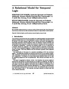
2 Multimedia Information System Model and Assumptions Multimedia applications impose diverse service requirements for presentation, storage, and retrieval. A promising solution to this problem is to use the object-oriented model in which each information unit is treated as an object with a topological structural description, e.g. graph model, associated with it. The object-oriented model is a natural way to model diverse media which require both exibility and extensibility. The main functions are de ned as methods which are procedures that implement operations de ned on an object. A request to perform an operation on an object is accomplished by sending a message to the object, i.e. a method invocation. Several multimedia system models have been proposed in recent years [BCG+90, Mas87, LG90b, Sve87]. A typical multimedia information system consists of four modules: user interface, object composition manager, database management system, and media managers. Figure 1 depicts the system architecture of a multimedia information system. The user interface provides the query or browsing facilities for media retrieval. It also provides some tools to construct a multimedia presentation with consistent temporal relationships among its media objects. In our approach, a multimedia presentation's temporal and spatial information are captured in a structure called Synchronization Relation Tree (SRT). The object composition manager is responsible for enforcing the temporal and spatial relationships among the multiple media objects during actual presentation. The functionalities of the database management system include schema management, concurrency control, recovery, version control, data integrity, etc. In this architecture, it is assumed that access to each media is directly governed by a media manager. The media manager can supply the timing information of the media object under its control. The timing information of a media object consists of the estimated and actual setup time as well as the runtime. The estimated setup time is the minimum time between the request for an object and its rst availability to the user. It
4
User User Interface Object Composition Manager Database Management System
�PP �� PP � � P �
Media Manager1
� �
Medium DB1
Media Media Manager 2 Manager3
�� ��
Medium DB2
�� ��
Medium DB3
� �
Figure 1: Multimedia Information System Architecture excludes delay due to dynamic system factors such as workload 1. The actual setup time is only available during presentation. A media manager manager is assumed to adhere strictly to the actual setup time it supplies. An important observation made by [RV91a] is that the cost of copying multimedia is very expensive and any architecture for a multimedia system should avoid doing it. To avoid the copy of data from layer to layer in such a layered system architecture, we believe that an overlying data structure (a pointer based scheme as in [RV91b]) is assumed to exist. The data is physically accessed only at the time of rendition and until then, we assume that the layers communicate data instances in the form of the overlying data structures. As discussed in [LGCB91], temporal information has traditionally been used in maintaining historical information [Sno87]. An example is a highway sensor data collection and maintenance system. This system collects sensor data consisting of temperature and data collection time, which can be queried using a temporal query language, e.g. TQuel. In the case of multimedia information systems, temporal information is used for synchronization purposes. Currently, there are two major approaches to model temporal relationships among multimedia objects, namely instant-based and interval-based temporal speci cations. Instant-based temporal speci cation usually involves assigning reference points to two or more streams of media data and media synchronization is performed by matching reference points in di�erent streams. This scheme has been widely applied in the motion picture industry [LGCB91]. Instant-based representation has some di�culties in representing temporal relationships among multimedia data. First, since unique and absolute time references are used, the relative timing between multimedia objects is lost when part of a data stream is edited. Second, it is not exible because a small change in a process' timing can cause 1 Workload includes IO activity, number of active processes and the bu�er usage metric.
5
revision of the whole process. Interval-based temporal speci cation models the presentation (runtime) duration of multimedia objects as time intervals. Allen in [All83] has shown a set of thirteen possible temporal relationships between two temporal intervals. Since a time instant can be captured as an interval with zero length, the interval-based representation is therefore more expressive than the instant-based representation. Our proposed scheme is based on an interval-based temporal speci cation model.
3 Temporal Relationship Speci cation and Scheduling Problem The synchronization within a multimedia presentation begins with a user specifying the desired temporal relationships among media objects and ends with a set of complete schedules for the objects. The schedules are then given to the media managers to initiate the actual presentation. A temporal relationship speci cation may contain runtime information of the media objects and their orderings. Coming up with a consistent speci cation is a non-trivial task for the user. The user may lack the knowledge of consistency or may simply make some mistakes in the speci cation. For example, the user may specify two video objects to start and end together without knowing that they have di�erent runtimes. Even if the user speci es the temporal relationships consistently, it may be impossible to guarantee that the actual presentation will follow the speci cation since accurate setup time information may only be available just before actual presentation. The actual setup time information may depend on static factors such as hardware, I/O device, media type, data size, etc. It may also depend on dynamic factors such as network load and system workload. In this section, we describe a framework in which temporal relationship speci cation and scheduling problems are handled in two stages, i.e. speci cation phase and scheduling phase. The rst is concerned with assisting a user to arrive at a consistent temporal relationship speci cation. A partial schedule is computed by using the estimated setup time. It is partial because the actual setup time is not available in the rst stage. The schedule of a media object is the point in time when the presentation method of the media object has to be invoked in order to show the object at the desired time. Scheduling phase involves the completion of a partial schedule. Since the scheduling phase is processed just before the actual presentation, any processing involved in this stage must be e�cient. This can be achieved by delegating as much work as possible to the speci cation phase. Figure 2 depicts these two stages.
3.1 Speci cation Phase
The primary objective of the speci cation phase is to capture the temporal relationships existing in a multimedia presentation and to perform consistency checking on the temporal relationships. This reduces the work left to be done in the scheduling phase. As shown in Figure 2(a), speci cation phase consists of three main steps. First, a temporal relationship speci cation is constructed by the user with the help of some speci cation editing tools. Second, a consistency check is performed on the speci cation to verify that the runtimes of 6
-
User
Temporal Relationship Speci cation ?
Temporal Speci cation
Consistent Temporal Speci cation and Partial Schedule
?
Consistency Analysis
?
? ��Z Is ZZ No ��Speci cation Z ZZConsistent? � � Z Z��
Dynamic Schedule Completion
actual setup time
?
? Yes Consistent Temporal Speci cation
Complete Schedule for Each Media Object
?
Partial Schedule � Generator
�
estimated setup time
?
Object Composition Manager
?
Consistent Temporal Speci cation and Partial Schedule (a) Speci cation Phase
(b) Scheduling Phase
Figure 2: Temporal Relationship Speci cation and Scheduling
7
the media objects are consistent with the desired temporal relationships. If any inconsistency is detected in the speci cation, the user will be noti ed and he can choose to modify the initial speci cation before re-submitting it to the consistency analyser. Once the speci cation satis es the consistency check, the partial schedule of each media object is generated by using the estimated setup time information. The consistent speci cation can be stored together with the partial schedules in the repository for future reference or it can be shipped to another platform and used there. The third step involves the generation of a partial schedule. This is based on a static analysis of the speci cations. The partial schedule is used in the next phase of the presentation process, and is used by the media manager's scheduler to schedule the rendition of appropriate media instances. In Section 4 of this paper, we will introduce a Synchronization Relation Tree (SRT) representation as a mechanism to formally specify the temporal relationships among media objects.
3.2 Scheduling Phase
Scheduling phase is carried out by the object composition manager just before the actual presentation begins. In this phase, the partial schedule of each media object is transformed into a complete schedule. The complete schedule has to be generated quickly in order to schedule actual presentation in real-time. The e�ciency of the completion process crucially depends on the amount of work that can be performed during the speci cation phase. During the process of completing schedules, the actual setup times are provided by the media managers. In Section 5 of this paper, we propose a pair of message passing protocols which, given a consistent speci cation in the form of SRT together with the partial schedules, will produce a set of complete schedules. With the complete schedules of all media objects in the presentation, the object composition manager invokes the objects' presentation methods according to their schedules. Eventually, the media objects will appear in the presentation in the order indicated by the temporal relationship speci cation. Here, it is assumed that the media managers are able to provide an accurate setup time information and adhere to it strictly. In a system that does not support real- time scheduling and presentation, the media managers may not be able to provide accurate setup time information. The scheduling phase may have to be modi ed to cope with the unpredictable setup delays. In section 6, we describe one possible approach to handle this problem.
4 Synchronization Relation Tree for Temporal Relationship Speci cation A multimedia presentation can be viewed as a series of shots. Each shot consists of one or more multimedia objects integrated together to form a meaningful episode of the whole presentation. Proper integration of multiple media objects is essential to achieve a coherent and meaningful presentation. For example, a multimedia car advertisement may consist of a sequence of shots each of which presents a short description of a speci c car model. Within a shot, a car image object is required to appear simultaneously with an audio object which 8
describes the car model. In this section, we introduce a formal temporal speci cation model, called the Synchronization Relation Tree (SRT), which could be a realization across various layers of architecture.
4.1 Synchronization Relation Tree (SRT)
The temporal relationships among media objects in a shot is captured in a SRT as two kinds of nodes, namely internal and leaf, connected to form a tree structure. The leaf nodes represent multimedia objects to be presented. The attributes of a leaf node include setup time, runtime and a reference to the object repository. The internal nodes of a SRT are used to express the temporal relationships among multimedia objects. There are two types of internal nodes, namely the Equal (EQ) node and the Sequential (SEQ) node. An EQ node requires its child objects to be presented in parallel whereas a SEQ node requires its child objects to be presented serially in the left to right order. A special kind of leaf node, representing delay, is introduced to represent potential slack time between multiple media segments. Delays have runtime values explicitly speci ed by the user. Delays are required to capture the semantics of certain temporal relationships as described in Section 4.2. Only a SEQ node can have one or more delay objects as its immediate children. For the illustration of these concepts, consider the following example: The temporal relationships in a multimedia slide presentation are shown in Figure 3(a). Note that di�erent regions associated with the various media types include video, images, and text. The presentation consists of a sequence of synchronized text, image, and visual elements of varying duration. There are nine multimedia objects in this shot, in which six are image objects, two are text objects and one is a video object. Image objects I11 and I21 appear time units after text objects T1 and T2 begin. Video object V, and image objects I12 and I22 begin at the same time, as do images I13 and I23. An SRT representation of this shot is shown in Figure 3(b). The root object, an EQ node, indicates that all its child objects must begin simultaneously. Its leftmost child, which is a SEQ node shows that a delay object D precedes both I11 and I21. The delay object D has a runtime of time units. Subsequently, there is simultaneous appearance of V, I12 and I22. I13 and I23 are shown together (they are children of the same EQ node) right after I12 and I22 disappear, and while V is still on. d
d
4.2 Modeling Temporal Relationships Using SRT
In this section, we show the SRT as a structured approach for representing synthetically constructed temporal relationships within a shot of a multimedia presentation. SRT model treats all synchronizable objects as temporal intervals and allows the user to express any temporal relationship between a pair of temporal intervals. The concept of temporal intervals introduced by J.F. Allen [All83] is shown in Figure 4. Except the equal relationship, each of these temporal relationships has an inverse which is not shown in the diagram. In Figure 4, we show how each of these possible temporal relationships can be modeled using the SRT. Meet and Before relationships can be directly represented by a SEQ node except that a delay object has to be inserted between the child objects of the latter relationship. Equal relationship can be represented by an EQ node. Start, Overlap, During and 9
�� EQ
Q #�� QQ �� # #
Video
SEQ
V
Image
�
d - I11
I12
I13
Image
�
d - I21
I22
I23
Text
T1
Text
T2
T1
T2
�� HH , H , �� HH �� ,
d
EQ
EQ
�� �� � A � D A DD � �� �� � I11 I21 V SEQ �� , \ , , �� \ �� \ EQ EQ �� � C ��� S �
I12 (a)
C
I22
�
I13
S
I23
(b)
Figure 3: Synchronization of Multimedia Objects in a Shot Finish relationships can also be represented by a combination of EQ nodes and SEQ nodes by inserting appropriate delay objects. Although any temporal relationship can be speci ed between two temporal intervals that represent the presentation duration of multimedia objects, there is still a need to provide an abstraction mechanism for modeling complex temporal relationship speci cation. It is often desirable to group multiple temporally related multimedia objects together to form higher abstract objects so that temporal relationships can be built among these higher abstract objects. For example, in designing a multimedia lecture on music composers, it is often natural to order the presentation by the musical periods, i.e., the composers in Renaissance period are introduced before those in Classical period, while the composers in Romantic period are introduced after the Classical composers but before the Modern composers. Within each temporal interval that represents a musical period, there is an ordered sequence of several sub-intervals each of which is allocated to present each composer and his work. Using this hierarchical approach, the temporal relationship speci cation for a multimedia lecture can be constructed in a structured manner that will be easy to understand, debug and modify. In this paper, we consider temporal relationship schemes that can be constructed hierarchically. We call this hierarchical temporal relationship speci cation. A hierarchical temporal relationship speci cation is (recursively) de ned as follows. De nition 4.1 : Hierarchical Temporal Relationship Speci cation � A single multimedia object is a hierarchical temporal relationship speci cation. � Two or more hierarchical temporal relationship speci cations which are not related to any other hierarchical temporal relationship speci cation can have any of the thir10
....... d.......
Ma before Mb:
Ma
Ma meets Mb:
Ma
Ma overlaps Mb:
Ma ..... d1 ...
Ma during Mb:
........
.......d1 . ........
�� SEQ� �
? ? ?
Mb
Mb d �� SEQ � � ? @
Ma
Mb d2 Mb
�
? ?
Mb �� EQ � ��@ ���� @� � SEQ. SEQ. � � � �
-
� �
�? ?
Ma nishes Mb:
Ma equals Mb:
d ....... ........
..... .
� �
d
Ma
@ @
d2 �� EQ "� � " �"� @ @ @ SEQ. � � Mb . . . ... � � d Ma �� EQ "� � �""� @ @ @ SEQ. � � Mb . . . . � . . � d Ma �� EQ � � @ ?
� d-
Ma Mb
..... .
Mb d1 �� EQ "� � �""� @ @ @ SEQ Mb � � ? @
Ma
d1 Ma starts Mb:
@ @
Ma
d2
Ma Mb
@ @ @
Ma Mb
Ma Mb
? ?
Ma
@ @
Mb
Figure 4: Temporal Relationships and their equivalent SRTs
11
teen temporal relationships established between them to form a hierarchical temporal relationship speci cation. The above de ned hierarchical temporal relationship speci cation can be expressed using a SRT with the multimedia objects as leaves and the temporal relationships between sub-hierarchical temporal relationship speci cations as internal nodes having two or more subtrees.
4.3 SRT Processing at Speci cation Phase
In general, a SRT captures all the abstract relationships between time intervals. However, in general, not all SRTs can be presented unless there is a technique for 'extending' media objects beyond their play-out time. In our scheme, we will not consider such cases and subsume that the SRT is consistent. De nition 4.2 : Consistent SRT A consistent SRT is de ned as 1. A single multimedia object is consistent in its interval of existance (equal to its runtime). 2. If 1,...., n are the children of an EQ node, with 1,... n being their runtimes respectively, then EQ is consistent i� 1 = ... = n in the time interval R (which is equal to any of the is, i 2 1..n). 3. If 1,...., n are the children of a SEQ node, with 1,... n being their runtimes respectively, then SEQ is consistent in the time interval R (which is equal to Pni=1 i ), i� all i s are consistent. 4. Any hierarchical construction with 1,2 and 3 is consistent. 5. Nothing besides 1,2,3 and 4 is consistent. To describe the processing of a SRT at the speci cation phase for the labelling of the SRT at each intermediate step. The label of the SRT describes the extent of temporal relationship information in the internal nodes of the SRT. Let srt be an instance of a SRT. Let T be the temporal synchronization data in the internal nodes of the SRT. Then, at any state of transformation, the SRT will be denoted by srt(T). T may be a label comprising various temporal speci cations (which is augmented by each of the subsequent transformation). Typically, at user speci cation, T is incomplete and unveri ed, and by a sequence of transformations, this label is augmented and hence completed. Deriving a consistent srt( f ) is the nal objective. Table 1 summarizes the notation used in subsequent discussions. C
C
R
R
R
R
R
R
R
C
C
R
C
T
Symbol Description ith child node from the left i Setup Time of i i Runtime of i i Display Time N S
N
R
N
D
12
Table 1 Initially, the user submits a presentation sequence, denoted by srt(), with no synchronization information at the internal nodes. For each leaf, the user speci es the temporal data at the leaves (run time for the media object) and the spatial information (position of the rendering of the media object during presentation). At this stage, the SRT speci es the abstract temporal relationships between the media objects. Next, srt() is checked for temporal consistency. This is done by a single upward message passing protocol. Because of the hierarchical composition of the SRT, a bottom-up check of consistency at an internal nodes ensures the subtrees rooted at it are consistent. Temporal consistency is checked by the following two methods : For EQ node : Method Time Consistent EQ (Message :\Time-consistent" ; Argument : None ; Result : R, f INCONSISTENT,CONSISTENT g ) Begin For each child node i Receive i as result Receive state of consistency (of subtree rooted at i) as result If ( is unequal OR any subtree returns INCONSISTENT) then Return (INCONSISTENT) else Begin Store R Send R ( = i: i 2 1...n) Return(CONSISTENT) End End For SEQ node : Method Time Consistent SEQ (Message :\Time-consistent" ; Argument : None ; Result : R, f INCONSISTENT,CONSISTENT g) Begin For each child node i Begin Receive i from i R := R + i Receive state of consistency (of subtree rooted at i) as result End Send R to parent If any subtree returns INCONSISTENT then Return ( INCONSISTENT ) Else Return(CONSISTENT ) End N
R
N
R
R
N
R
N
R
N
13
The consistency checking phase results in a boolean indication about the consistency of the presentation. If found inconsistent, the user could be prompted for the exception and asked to resubmit a modi ed srt(). Furthermore, the consistency check transforms the srt() to srt([R]). To clarify the use of a consistent SRT, we shall label the consistent tree as C-srt([R]). The aim of the speci cation phase is to perform as much of the computations of the presentation through a static (compilation) phase. In our scheme, this involves the estimation of the lower bounds for the setup time for the media objects. We assume that the lower bound on the setup time lb(S) for a media object is the time for setting up the media stream for rendering/playing on a lightly loaded system. This estimate would be a function of the media size, the media format, the cost of media I/O, the presentation method used to render/present the media stream, the system con guration, etc. This estimate could be provided by the media manager. This proceeds in a bottom-up pass, as these estimates need to be computed at the leaves (media instances). The resulting SRT from this transformation is C-srt([R,lb(S)]), where lb(S) denotes the lower bounds for the setup times. The need for this additional cycle of message propagation is to provide the user the estimated setup time for the overall presentation. This comprises the compilation (static) phase. C-srt([R,lb(S)]) may be reported to the user, who could either accept the speci cation or edit and perhaps give better estimates of the setup times. C-srt([R,lb(S)]) may be stored or transported for future use at another site (with similar system con guration). However, C-srt([R]) could be transported across systems, making the presentation highly portable.
5 SRT Processing at Scheduling Phase The main objective of the scheduling phase is to determine the exact schedules for the media objects so that their temporal relationships can be presented correctly. In this section, we assume that the media managers can provide accurate setup times for the media objects. This implies that the underlying system can support real-time requests. The dynamic schedule completion is performed by two protocols, namely the upward and downward message passing protocols. The rst obtains the initial actual setup time and runtime of the media objects and propagates them to the root node. The computation e�ort of actual setup time can be reduced by using the partial schedule pre{computed at the speci cation phase. The downward message passing protocol computes the display time of the media objects and distributes them to the leaf nodes of the SRT. The display time of a media object is de ned as the time (relative to the beginning of the multimedia presentation) when it must appear. The nal schedule of a media object can then be derived by subtracting its setup time from its display time. At this time, the nal schedule and spatial information is given to the object composition manager which schedules and integrates various media with the aid of media managers. Throughout the two message protocols, the internal nodes of a SRT are treated as composite media objects with setup time, runtime and display time. At the root node, setup time and display time are synonymous since the amount of time before the display of the entire presentation is exactly the setup time. Online monitoring of the presentation at runtime can be preformed by using techniques of meta-scheduling as described in [And90]. 14
To support the two message passing protocols, two methods are de ned for each object class in the SRT. They are AcqTime and DisTime and can be invoked by sending acquiretime and distribute-time messages respectively to the object involved. AcqTime method is invoked during the upward message protocol. An invocation of AcqTime at an object returns the actual setup time and runtime values required by the SRT rooted at the object. There is no argument needed to invoke this method. DisTime method is invoked during downward message protocol. An invocation of DisTime at an object receives two input arguments as part of the distribute-time message. These are the display time and runtime values decided for the SRT rooted at the object. DisTime method does not produce any result value. Like any object methods, the invocation of either the AcqTime or DisTime methods will cause the message sender to be blocked until the method execution is completed. Details of the upward and downward message passing protocols are described in the following subsections.
5.1 Upward Message Passing Protocol
Upon request for presentation, the system sends an acquire-time message to the root of the corresponding SRT. The AcqTime method invocation in turn sends an acquire-time message to each of its child objects. Invocation of the AcqTime method on any child object, which is not a leaf object, will continue to propagate the acquire-time message down the SRT until the leaf nodes are reached. The AcqTime method invocation at a leaf object obtains the setup time and runtime of the media from the corresponding media manager. This timing information is then returned to the parent object as the result of the method invocation. The initial timing information of multimedia objects are consolidated at each internal node and propagated upwards to the root. Upward message passing protocol terminates when the root object receives the timing information from all of its child objects. The timing information collected from child objects is processed di�erently within the AcqTime method, depending on the object class on which the method is invoked. The purpose of consolidating the timing values from the child objects is to compute the correct timing speci cations which guarantee the temporal relationships among the child objects. When an EQ object receives setup time and runtime information from all its child objects as the results of invoking their AcqTime methods, the AcqTime invocation at the EQ object returns the maximum setup time and runtime of its child objects as its result. In doing this, the EQ object guarantees that its child objects have su�cient setup time to present themselves in parallel. Maximum setup time is chosen because the system cannot reduce the given minimum setup time for a media object. The following pseudocode describes the AcqTime method for EQ object class. Method AcqTime ( Message:\acquire{time"; Argument: none; Result: S, R ) Begin For each child node i send message \acquire{time" to receive i and i as results return( Max( 1, 2,..., n), R) N
S
S
R
S
S
15
Ni
and
.......
S1
........
S2 S3
........
.......
R .......
.......
.......
R
R
.......
S2
.......
........
S2
.......
.......
S2
R
.......
R
R
Figure 5: End Figure 5 shows an example of AcqTime method invocation at an EQ object. In this example, the EQ object has three child nodes, namely 1, 2 and 3 whose setup and runtimes are ( 1, ), ( 2, ) and ( 3, ), respectively. Let's assume that 2 1 3. The AcqTime method selects the largest setup time, i.e 2, to synchronize the three media objects. This is shown in the right diagram of Figure 5. When a SEQ node receives setup time and runtime information from all of its children, the corresponding method de ned for the class SEQ will compute the proper setup time for its child nodes to be presented consecutively in the left to right order. Suppose that an SEQ node has n children and let F and F be the nal setup time and runtime the node returns to its parent. The objective here is to ensure that a child object must be properly setup by the time its left sibling object completes its presentation. We assume that the setting up of a media object can be carried out while some other media object is being presented. This can be accomplished by having the setting up done in a memory bu�er separated from the one being used for presentation. Once the media object has been setup, it can be presented instantaneously by assigning the presentation bu�er pointer to the address of the setup bu�er. In other words, the roles of setup bu�er and presentation bu�er have been switched. P n Let F be the sum of the runtimes of the n children, i.e., F = i=1 i. To compute F , ?1 let's assume that the intermediate setup time for n-1 children is I . If I + Pni=1 i n, it means that the intermediate setup time together with the runtimes of the n-1 children on the left does not provide adequate time for the setup of the nth child, and F is assigned the ?1 . Otherwise value n - Pni=1 i F is assigned the value I . The following is the pseudocode which describes the AcqTime method for the SEQ object class. N
S
R
S
R
S
N
N
R
S
> S
> S
S
S
R
R
R
R
S
S
S
R
S
S
R
S
S
Method AcqTime ( Message:\acquire{time"; Argument: none; Result: S, R ) Begin For each child node i send message \acquire{time" to receive i and i as results N
S
R
16
Ni
and
< S
........
S1
........
S2
........
S3 ........
.......
R1 .......
.......
R2
S1
.......
.......
R1+R2+R3 R2
R1
R3
R3
Figure 6: ....... S1........ R1 .........
........
S2
........ S3
........
........
R2
........ S2-R1 ........ R1
R2
R3
R3
Figure 7: S := 1 R := 1 i := 2 For all child nodes from left to right if (S + R i ) then S:= i - R R := R + i i := i+ 1 Return ( S, R ) S
R
< S
S
R
End Figure 6 and 7 show the update of timing information by an SEQ object. In this example, the SEQ object has three children 1, 2, 3 whose setup and run time are ( 1, 1), ( 2, 2), and ( 3, 3), respectively. Let's assume that the setup and run times have the following relationships as shown in Figure 6: 2 1 3, 1 + 1 2, and 1 + 1 + 2 3. The SEQ object chooses the setup time of the leftmost child object 1, and the sum of the runtimes of three children to serially synchronize the three media 1, 2, and 3. However, if the setup time and runtime have the relationship, 1 + 1 2 , as shown in Figure 7, the SEQ object computes 2 - 1 as the new setup time to synchronize 2 as soon as 1 nishes. N
S
N
N
S
R
S
R
R
S
> S
> S
S
R
> S
S
R
R
> S
S
N
S
S
R
R
N
N
< S
N
17
N
5.2 Downward Message Passing Protocol
After the root node receives the setup time and runtime from all its children, the downward message passing protocol begins. The display time at the root node is set to be its setup time. The protocol begins by invoking the DisTime method at the root object with the display time and run-time as input arguments. Downward message passing protocol terminates when all the leaf nodes receive their display time and runtime. Each leaf node computes its schedule time by subtracting its setup time from its display time. The schedule and the spatial information are then given to the object composition manager which schedules each medium and integrates various media with the aid of the media managers. For example, if SCH, S and R are the schedule time, setup time and runtime of a media object, the object composition manager will invoke the presentation method SCH time units after the presentation begins. The media manager which supports the presentation method guarantees that the media object will appear S units of time after the invocation. The display time is computed by the DisTime method de ned within the EQ and SEQ object classes. The invocation of DisTime method at an EQ or SEQ object computes the nal timing information which guarantees all temporal relationships that exist in the entire presentation. When an EQ object receives a distribute-time message from its parent along with the display time and runtime information, the DisTime method is invoked. Since the EQ object's children are expected to begin and end together, the EQ node sends each of its child objects a distribute-time message with the same display and same run times as arguments. The following pseudocode describes the DisTime method for the EQ object class. Method DisTime ( Message:\distribute{time"; Argument: D, R ; Result: none ) Begin For each child node i send message \distribute{time" to End N
Ni
with arguments D and R
When a SEQ object receives a distribute{time message from its parent along with the display time D and runtime R information, the DisTime method is invoked to compute the display time and runtime for each child object so that they can be presented consecutively in the left to right order. The display time each child object receives di�ers from the setup time according to its position in the entire presentation. If the position of a child is ( + 1)th from the leftmost child node, it receives the display time which is equal to D plus the sum of runtimes of i objects from the leftmost one. The DisTime method of the SEQ class is as follows. i
Method DisTime ( Message:\distribute{time"; Argument: D, R ; Result: none ) Begin 18
Text
Text:
Image
Image:
Video
Video:
T=8
(a)
....... ....... I1=3 d=2 ....... ....... V=3 d=2
I2=3
(b)
Figure 8: send message \distribute{time" to leftmost child with argument D and 1. send message \distribute{time" to 2nd leftmost child with argument D+ 1 and 2. .... send message \distribute{time" to leftmost child with argument D+ 1 + 2 + + n and n . R
R
R
R
R
:::
R
R
End
6 Example Presentation In this section, we present a detailed example which illustrates the ideas presented in the preceding sections. The example contains both static and dynamic data in the form of video, image, and textual data which require synchronization at the presentation level. Figure 8(a) presents a typical presentation which contains one text paragraph at the top of the screen, two consecutive images in the middle of the screen, and a video segment at the bottom of the screen. The synchronization requirements of a single episode of the presentation are shown in Figure 8(b), which shows the temporal relationships between the various elements of the presentation. This timeline representation shows that the textual component should persist for the entire episode, while the video and rst image components begin presentation after a delay of d time units. Both the video and the rst image components end at the same time. The second image begins at the same time as the video component nishes and ends with the text component. The corresponding SRT for the synchronization information of Figure 8(b) is shown in Figure 9. We assume that the media objects, i.e. leaf objects of the SRT, hold the spatial information represented by Figure. 8(a). The upward and downward message passing protocols are is shown in Figures 9(a) and 9(b), respectively. The number on an arrow and in the associated rectangle represent the setup time and runtime, respectively. Let's assume that each medium object gets the setup time and runtime shown in Figure 9(a) at the 19
�
.......4....... ..EQ... ....� .� ...
�
........4........
T
9
� �
bb b� b
2+3+3
2+3+3 SEQ .. .. .P .....� .P . . .. "" . P " � ..2... PPP " d=2 EQ ..... .. ... 3 I2 .... ..... . ..� .3. .. 2
I1 1 ........ ....... 3
....4.... ........
...... ...... 3
J J
� ..4 ... ..... .. .. 2+3+3 EQ �� b � b . b ...... ......� � .� b .....4. ........ 2+3+3 T SEQ. � P " . . PP 9 ... .."" � .." ..6... PPP..... ..... .. ... 3 I2 d=2 EQ � 4 9... ... ... ...
J ...... ..... 2 . . .
.. I1 ......6.. ........ 3
V ......2.. ........ 3
(a)
.
...... J
...... ..... 3
V ......6.. ........ 3
(b)
Figure 9: beginning of the upward message passing protocol. The lower EQ node returns the larger setup time 2 and runtime 3 to its parent SEQ node. Subsequently the SEQ node returns zero setup time and the runtime 2+3+3 which is the sum of its three children's runtimes to its parent EQ node. After the root EQ node returns the setup time 4 and runtime '2+3+3', the upward message passing protocol ends. The downward message passing protocol begins when the root EQ node sends its display time 4 and runtime 2+3+3 to its children. The medium object T's display time and runtime is determined after it receives timing information from its parent EQ node. After the SEQ node receives the timing information from its parent, it distributes the display time and runtime to its three child nodes. Since the runtime SEQ receives is the same as the runtime it sends to the EQ node during the upward message passing protocol, the EQ node will receive the display time 6 and runtime 3 where 6 = 4 + 2. At the same time, the medium node for the second image component will receive the display time 9 and runtime 3 where 9 = 4 + 2 + 3. Thus, this medium object's nal display time and runtime is determined at this time. Finally, the lower EQ node will distribute its display time and runtime to its two child nodes. The display time and runtime of the medium objects, which represent the rst image component and video image component, is now determined. Having received the display time, each leaf node is then assigned a schedule time which is its display time minus its setup time. After receiving the schedule and spatial information from all the leaf objects of a multimedia presentation, say at time t, the object composition manager begins to schedule and integrate various media. The text component will be presented for a period of 8 time units at t+4. The video component will be presented for a period of 3 time units at t+6 to synchronize with the beginning of the text. The rst image component will be presented for a period of 3 time units at time t+6 to synchronize with the video, while the second image component will be presented for a period of 3 time units at time t+9 to synchronize with the both the rst image and the text.
20
Tool1
Tool2
Tool3
Object Composition Manager
Speci cation Tools Dynamic Schedule Completion
Multimedia DBMS
Figure 10:
7 Conclusions We have presented an intuitive approach to the multimedia temporal speci cation and scheduling problems in this paper. The problems are tackled in two phases, namely speci cation phase and scheduling phase. The Synchronization Relation Tree is proposed as a formal representation of temporal relationships among media objects. A pair of message passing protocols are proposed to schedule the appearance of media objects dynamically. In case the underlying system does not support real-time system requests, the scheduling can be supplement with a triggering mechanism. Our ongoing research aims at modelling the runtime indeterminism of the scheduling phase. We are exploring schemes for translating presentation requirements to issues of bu�er allocation and data placement on the disk. The main contribution of this paper is that we proposed a new methodology to solve the temporal relationship speci cation problem for multimedia systems. Such methodology describes all important activities that have to performed by any multimedia presentation system. We also proposed new representation and new techniques which together demonstrates the methodology. It is anticipated that our approach to formally represent temporal relationships among di�erent media objects will demand a set of tools that help the user to construct the temporal relationship speci cation in applications such as multimedia document browsing, multimedia presentation, multimedia advertising, etc. Our ongoing research is addressing the issues in the design and implementation of such tools.
21
References [All83] [And90] [BCG+90] [CRT91] [KNS90] [LG90a] [LG90b] [LG91a] [LG91b] [LGCB91] [Mas87] [RV91a] [RV91b] [Sno87] [Ste90]
J.F. Allen. Maintaining knowledge about temporal intervals. Communications of the ACM, November 1983. D.P. Anderson. Meta scheduling for distributed continuous media. Technical Report 90-006, University of California, Berkeley, October 1990. P. Berra, C.Y.R. Chen, A. Ghafoor, C.C. Lin, T.D.C. Little, and D. Shin. Architecture for distributed multimedia database system. Computer Communications, May 1990. M. Carlo, F. Rabitti, and C. Thanos. Conceptual modeling of multimedia documents. IEEE Computer, October 1991. W. Klas, E.J. Neuhold, and M. Schre . Using an object-oriented approach to model multimedia data. Computer Communications, May 1990. T.D.C. Little and A. Ghafoor. Network considerations for distributed multimedia object. IEEE Network Magazine, 4(6), November 1990. T.D.C. Little and A. Ghafoor. Synchronication and storage models for multimedia objects. IEEE Journal on Selected Areas in Communications, 8(3), April 1990. T.D.C. Little and A. Ghafoor. Multimedia synchronization protocols for broadband integrated services. to appear in IEEE Journal on Selected Areas in Communications, 1991. T.D.C. Little and A. Ghafoor. Spatial-temporal composition of distributed multimedia objects for value-added networks. IEEE Computer, October 1991. T.D.C. Little, A. Ghafoor, C.Y.R. Chen, and P.B. Berra. Multimedia synchronization. Data Engineering Bulletin, 1991. Y. Masunaga. Multimedia databases: A formal framework. In IEEE O�ce Automation Symposium, April 1987. P. V. Rangan and H. M. Vin. File system design for digital video and audio. In Proc. of the 13th Symposium on Operating Systems Principles, October 1991. P. V. Rangan and H. M. Vin. A testbed for digital audio and video. In Usenix, Summer 1991. R. Snodgrass. The temporal query language tquel. ACM Transactions on Database Systems, June 1987. R. Steinmetz. Synchronization properties in multimedia systems. IEEE Journal on Selected Areas in Communications, 8(3), April 1990. 22
[Sve87]
J.S. Sventek. An architecture for supporting multi-media integration. In Proc. IEEE Comput. Soc. O�ce Automat. Symp., April 1987. [WKL86] D. Woelk, W. Kim, and W. Luther. An object-oriented approach to multimedia database. In ACM SIGMOD, 1986.
23
A An Alternate Approach to Media Scheduling The section on the SRT methodology to solve the problem of temporal speci cation described the steps involved in transforming a user speci ed srt() to a C-srt([R,S]). The task of implementing these steps in non-trivial, when the requirements of real time support by the media manager is relaxed. In a non-real time environment, certain additional mechanisms are needed to ensure the synchronization. This might be done at the expense of introducing a degree of non-determinism. In our experience with a prototype implementation, we found that the estimation of the setup time is a di�cult and unyielding task in a non-real time media manager. The reasons for this are easy to observe when the dynamics of system are included. This has lead us to believe that central to the success of any presentation system is the accurate estimation of the setup time. A study by one of the authors, aimed at relating the media size, format and type to its setup time, yielded no struct correlation between them. It was found that the media instances showed large uctuations in the in measured setup times, when they were run under di�ering system loads, times. This has lead us to believe that estimation of the set up time through a parametrization of the object attributes is not the solution to the problem of setup time estimation in presence of changing system conditions. Therefore accurate setup time estimation is not possible with current non-real time media managers and thus an alternate technique is needed, for realizing practical systems. The alternate technique uses the idea of a trigger-based, nal step synchronization, along with setup time estimation. This approach still uses scheduling, but adds a new process, the presentation coordinator (as part of the Object Composition Manager), to the system to meet the non-real time requirement of existing media managers. A presentation method is assumed to comprise three phases in processing its media object. An initial media read phase (phase I), reads the media object o� the disk and locally bu�ers the media data. The conversion phase (phase II) is the decoding algorithm that performs the required transformation of the raw data for rendition on the medium's output device. The third and nal phase (phase III) involves rendition of the processed media onto the physical output device. When displaying static medium objects this is a simple sequence, but in dealing with continuous media, the three phases will be likely to be overlapped in time. Interleaving of the three phases, i.e pipelineing, is common in video data presentation. In the discussion that follows, we assume, if the three phases are pipelined then the media manager provides a steady rate of the media data after the rst pipelined sequence. Furthermore, we assume that the presentation methods provides at the end of phase II a trigger and that the presentation process is blocked till the process receives a trigger to proceed to completion. It is assumed that the process is in a suspend state while in the blocked queue, waiting for the trigger. After phase II, the phase III is assumed to take minimal time, as this is just a transfer of block data to the physical output devices. With such a model of the presentation method, a nal step synchronization could be achieved by dividing the setup times estimation into two quantities, the lower bound setup time ( the minimal time needed by the presentation method to read and process the media i.e minimal time for phases I, II, and phase III) and the time overrun due to the dynamic system load. The lower bound estimate can be done at the static phase of speci cation completion 24
as this can be obtained by modelling phase I as a simple read process and phase II by an algorithmic analysis. The lower bound setup time could be a function of the attributes of the media ( its type, size, format, etc. ) and this could be done analytically through a mathematical model. To achieve the synchronization in presence of the time overrun, the use of a trigger mechanism is suggested. A trigger is a event noti cation by a process to another unrelated one. A precess waiting for a trigger is assumed to be in a blocked state and remains in that state until the appropriate trigger is received. In the following discussion we shall omit to consider all overheads incurred by such inter-process communication without loss of detail. A process generating a trigger is assumed to be aware of the 'addressee' process and when needing to notify the process, does so instantaneously. The presentation of the SRT is achieved by a global media scheduling process and a set of presentation coordinating processes. The two work independent of each other and di�er in their scope and extent of participation. The media scheduling process schedules the media instances for display based on the partial schedule derived from the SRT. This schedule includes the lower bound on the setup times for the media instances. Every internal node of the SRT executes a presentation coordinating process. Each of these processes ensures a nal step synchronization of all its immediate children. Thus each presentation coordinating process ensure local synchronization within the subtree rooted at it. When a media instance gets scheduled for presentation, the presentation method proceeds into phases I and II of its execution and on completion of these two phases, generates a trigger to its parent presentation coordinating process (Figure 10). The presentation method then waits for a trigger from the parent presentation coordinating process to execute phase III and thereby rendering the media instance onto the physical device. The role of the presentation process (refer to algorithms) is to note the triggers received from its immediate children, and on receipt of these from all the immediate children, propagate the trigger upward (for higher, internal nodes). Like the presentation method, after the upward trigger noti cation, the presentation coordinating process, it waits for a trigger from its parent. At the root of the SRT, a downward trigger propagation is commenced on receiving the trigger from its immediate children. As this downward trigger is received by the internal nodes, they in turn broadcast the trigger to their immediate children. At the leaves, the presentation methods receive the trigger from their parent presentation coordinating processes, proceed into phase III of their execution and render their media instances. The trigger protocol for the two kinds of nodes, SEQ and EQ are described here. The protocol uses two synchronization primitives that can be implemented. 1. Signal(node) - sends a signal to node 2. Wait(node) - wait on a signal from node For EQ node Method Trigger Synch EQ () Begin For each child node i Wait( i) /* At this point we have signals from all the children N
N
25
To Parent 6 From Parent (Tpi & Tm)�� ? SEQ/ EQ �� 7 I Tpi � Tm � @@ @ / � �
media object
�� @ R Pi
��
S SRT S rooted at Pi S
Phase II Wait for trigger from parent6 Phase III
Phase I
?
Trigger sent to parent
Trigger received from parent
Figure 11: Trigger Sequence for Media Object indicating that phase II is complete for all immediate children */ Signal(parent) /* This propogates the signal for EQ nodes higher up the path to the root */ If node is not the root Wait(parent) For each child node i Signal( i) N
N
End For SEQ node Method Trigger Synch SEQ() Begin Wait( 1) Signal(parent) If node is not the root Wait(parent) Signal( 1) End N
N
For a trigger based implementation, the presentation methods need to be re-coded to provide this triggering capability. Implementations of Signal() and Wait() can be done by well known event noti cation methods like signal() in UNIX.
B Prototyping Based on the methodology described in this paper, we have developed a multimedia presentation prototype on a SPARCstation with color monitor and voice output. The prototype is 26
written in C and it runs in the X11 window environment. Currently, the prototype is able to read in a SRT speci cation in a text format and perform consistency checking. A dynamic schedule completion module based on pure scheduling approach has been implemented. For simplicity, the setup times for the media objects are assumed to be user-speci ed and guaranteed by the underlying system. A sample multimedia presentation which was run by the prototype implementation is described here. The presentation comprises three kinds of media objects - text, image and sound, whose temporal relationships are speci ed in a SRT as shown below. Its graphical representation is shown in Figure 12.
B.1 Sample Presentation Speci cation (
)
( SEQ ( EQ ( media : audio obj = media/dreamline.snd (10,15) ) ( EQ ( media : text obj = media/prism.txt (3,15) ) ( media : image obj = media/prism.gif (11,15) ) ) ) ( delay 10 ) ( SEQ ( EQ ( media : audio obj = media/trektheme.snd (10,20) ) ( SEQ ( media : image obj = media/vangogh.gif (7,10) ) ( media : image obj = media/renoir.gif (3,10)) ) ) ( delay 10 ) ( EQ ( media : image obj = media/Dali1.gif (7,10)) ( media : image obj = media/Dali2.gif (3, 10) ) ) ) )
The current speci cations includes the media type ( image/audio/text ), the runtime of the speci cation and the setup times for the media streams. The media object delay simulates a real time delay of the speci ed amount. delay objects can be viewed as null media streams with no setup time and runtime equal to the desired delay. The timeline representation of the presentation is shown in Figure 13. Figure 14 and 15 are snap-shots of 27
��
SEQ �� XX ��
�
� �
dreamline.snd (audio) " " "
l
l l ��
" "
�
Delay = 10
EQ �� � l
� �
�
EQ ��
prism.gif (Image)
trek theme.snd (audio)
@ @
XX ��
EQ ��
Delay = 1
e e
� �
� �
e Dali 1.gif e ��
SEQ
prism.txt (Text)
SEQ
���� �� % @ � � @ � � % �� @ �� %
�� e ��
EQ ��
" @ @
XXX XX XXX
Dali 2.gif (Image)
(Imge)
�� b � b � bb � �
vangogh.gif (Image)
renoir.gif (Image)
Figure 12: SRT Speci cation of the Presentation the presentation in progress at di�erent points in time. Prism.gif (Image) Prism.txt (Text) Dreamline.snd (Audio) 0 11
6
Vangogh.gif (Image) Renoir.gif (Image) rektheme.snd (Audio) 42
62
Dali1.gif (Image) Dali2.gif (Imge)
90 91
Time
Snapshot depicted by Figure 14
6
113
Snapshot depicted by Figure 15
Figure 13: Timeline Representation of Presentation
28
Figure 14: 29
Figure 15: 30