Mary Lou Maher. John S Gero. Milad Saad. Design Computing Unit. Department of Architectural and Design Science. University of Sydney NSW 2006 Australia.
Synchronous Support and Emergence in Collaborative CAAD Mary Lou Maher John S Gero Milad Saad Design Computing Unit Department of Architectural and Design Science University of Sydney NSW 2006 Australia
Design is rarely an activity that is commenced and completed by an individual. The more common design environment is one in which teams of designers work together towards a final solution. In this paper we consider issues involved in the development of computer-based design environments in which teams of design professionals can collaborate, focussing on the need for visual and underlying representations which can support multiple interpretations. We consider the environment as providing a shared workspace which facilitates both communication and progression of design ideas, concepts, and drawings. In the environment presented here, the shared workspace has two focuses: the workspace that designers see and interact with, and the workspace that provides an underlying computer-based representation for persistent memory. The emphasis is on providing representations that support emergence that occurs during collaboration. Keywords: collaborative design, team design, multi-user synchronous CAAD, shared representation, shared workspace, emergence.
1
Introduction
Computer-aided design (CAD) is established in the design professions as a tool for visualising and documenting a design solution. The users of CAD vary from computer operators, whose job it is to document a design for a designer, to designers themselves who wish to visualise a design while making changes and eventually final decisions regarding form. Regardless of who the user of a CAD program is, the mode of
use of a CAD system is currently limited by a single-user interface. This interface provides the technology for one person to view the drawing and make the changes in geometry or view. Implicit in this technology is the assumption that using CAD is an activity that is limited to an individual. Distributed CAD currently means that many individuals can access the CAD data, not that more than one person can work simultaneously on the same drawing, where each person sees the same view. In this paper, we present another perspective on distributed, collaborative CAD, one in which synchronous collaboration is accommodated through a multi-user interface to a more comprehensive CAD environment. In order for CAD to become more useful to designers there is a need to support the activities that designers participate in. Conventional CAD systems support drafting as an activity, improving the quality of the final drawings, facilitating changes to the design documents, and providing an electronic archival form of design drawings. A design professional becomes interested in these activities only after the major design ideas have been developed and a solution, in some form, already exists. New developments in CAD are directed at improving the utilities available to the individual using a CAD system to make the documentation activities easier and more sophisticated. For example, CAD systems strive to provide more friendly user interfaces, easier menus, better 3D modelling tools, easier access to DBMS, more realistic colours, etc. All these advances are important but do not change the nature of the use of CAD and do not bring it closer to the designer. It could be argued that these advances take CAD further from the designer because a substantial amount of training is needed to operate such CAD systems. Designers tend to be more interested in their design problems rather than learning how to use a complex computer program. Other CAD tools are available that provide support for designers that do not result in a final documentation in the form of production drawings. Such tools include 3D modelling systems, graphical interfaces to analysis, simulation, and optimization programs, knowledge-based expert systems, etc. These tools address another aspect of design where design development occurs through the use of the computer, yet many of these tools assume there is a design solution to start with or that the graphical documents for the solution are developed separately. Still these tools are unable to reach their potential impact on design due to the focus on design as an activity that starts with an initial solution which is then developed by an individual. The existence of the broad range of computer tools to support design has increased our expectations for CAD. We assume that a CAD system can provide a visual interface to the design solution. We assume a certain level of sophistication in modelling a design, such as 3D visualisation, rendering, animation, etc. We also expect a certain level of performance from the computer in terms of response time. When considering the support of synchronous collaborative design, two requirements can be identified: the resulting computer environment must at least provide the kind of sophistication that current single-user interface systems provide, and the nature of the interface must address the needs of the designer rather than a CAD operator.
Recent developments in distributed systems and computer-supported collaborative work as well as symbolic representation of design schemas, provide an opportunity to develop CAD systems that support collaborative design. In this paper we review the relevant recent developments and identify what these developments offer for CAD. Then we present a model for computer-supported synchronous collaborative design, focussing on the issues related to the development of shared workspaces. We conclude with the need for further research and development and a vision of the impact of this type of computer support on design professionals.
2
Distributed and Integrated Design Environments
Existing CAD systems offer powerful drawing capabilities and realistic representations of the design. The design data in CAD systems is represented as a set of graphic or symbolic objects (e.g. lines, polygons, text, etc). Attributes are attached to these objects to represent non-graphic information. Based on the nature of design as a collaborative work, distributed and integrated CAD have become important issues. Distributed CAD implies that the CAD data is available across a distributed network. Integrated CAD implies that the CAD data can be read by more than one computer program, for example CAD systems from a variety of companies and other types of computer programs such as analysis tools. The common approach to distributed CAD is the use of distributed databases. The hardware and software technology is being developed to support the communication and multi-user access to an electronic form of design data. The electronic form of the data ranges from shared files to shared DBMS access. Modelling of the design data provides the basis for establishing the semantics of the shared data. The assumption in distributed CAD is that access to the design data occurs through a predetermined CAD system or DBMS. The efforts towards CAD integration have resulted in the development of various data exchange standards, as well as many "non-standard" symbolic models. The aims of the data exchange standards have varied from exchanging drawing data to exchanging product models. DXF and IGES are results of efforts on the exchange of graphics databases between CAD systems which deal with geometric information such as lines, circles, etc. The lack of design features in data exchange standards such as topology, relationship, etc, has shifted the focus towards product data exchange standards. The focus on product modelling (e.g. PDES, STEP, etc) has placed an emphasis on 3D solid modelling of geometry and the essential features that can be given to models as well as on non-geometric data and modelling the product as a set of related concepts or objects. Design research focuses on an understanding of design, or on modelling design processes, as a prerequisite for developing computer tools to support design. The use of Artificial Intelligence (AI) as a paradigm for modelling design knowledge and design processes is a recent approach to design research. The focus of the models produced
from AI-related design research is not in graphic data exchange, but in symbolic modelling of the comprehensive design solution. These models currently focus on object-oriented approaches where the form, function, and/or behavior of the design are captured by attributes or represented in networks. Although a representation of non-geometric information can be stored in a CAD database, most CAD systems do not use this information. Design data is extracted from the database and fed to another system that can reason or execute computations with such data. Interfaces exist to manage the exchange of information between various systems. To deal with the diversity of computer-based design programs, integrated CAD systems provide a basis for data integration. One approach is the use of relational database management systems (RDBMS) in which data is stored as tables, and accessed and modified using a relational query language, e.g SQL. Another approach is the use of object-oriented database management systems (OODBMS), based on object-oriented programming techniques, with utilities found in database management systems, that support encapsulation and complex objects. OODBMS are still in the early stage of development. However, the object-oriented approach shows significantly more promise from a semantic expressiveness perspective. This approach has been applied in various research projects (e.g.(Sriram et al. 1991), (Sauce et al. 1992), (Poyet et al. 1990), (Law et al. 1991), (Fenves et al. 1990), etc).
3
Computer Supported Cooperative Work (CSCW)
Generally, the main concerns of computer-supported cooperative work (CSCW) are about the study and theory of how people work together, and how the computer and related technologies affect group behaviour. Research issues in this area range from discovering models for interaction to applications development. On the research front, researchers are concerned with modelling group communication ((Pankoke-Babatz et al. 1989), (Bannon and Schmidt 1991), (Smith et al. 1991), etc), the concept of information sharing ((Hennessy 1991), and DePaoli and Tisato 1991)), the requirements for activity management (Benford 1991), and capturing and representing group decision rational ((Lee 1990), and (MacLean et al. 1991)). In contrast, various techniques have been applied to enhance communication, coordination, and collaboration such as networking, concurrent processing, and windowing environment. These technologies help in producing CSCW applications which enhance teamwork. The current applications of this area are primarily in group meetings, long distance conferences, software development, game playing, and shared drawing system. Relevant research in CSCW includes architectures for multi-user applications ((Patterson 1990), and (Crowley et al. 1990)), models for a shared workspace (Ishii and Miyake 1991), and multi-user drawing tools (Dourish 1992). The application of this research to the design of physical objects is not well developed. The
distinctions made by computer-supported collaborative design include the need to share design drawings, ideas, and rationale, and to allow for emergence to occur amongst the collaborators, where other applications focus on sharing text or graphics in the form they were entered into the computer. In applying this technology to design, the concerns are in the sophistication of the drawing primitives and display, the representation of design information beyond what each person sees on the screen, and the use of underlying representations of the design that support emergence.
4
Emergence in Design
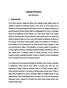
Emergence in design occurs when a new property that was not explicitly represented or intended is found in a design description. In order for a computer program to support emergence in design, two issues are relevant: representation of design intent and recognition of emergent properties. Design intent can be defined as the implicit design knowledge which leads to design decisions at any stage of the design process. An understanding and representation of design intent is required in a collaborative design session to allow the remote communication between designers and to extend the electronic representation of the design solution beyond the geometry or drawing data. Current research on explicitly representing design intent includes representing evolving artifact and design objectives (Ganeshan et al. 1991), representing the purpose or behaviour of design elements (Rosenman and Maher 1992) and representing the user/performance requirement at the design level (De!La!Garza and Oralkan 1992). The recognition of emergent design properties is necessary in a computer environment that supports design since emergence is an important and common aspect of design, particularly in visually-oriented design domains such as architecture (Mitchell 1989), and in synchronous collaboration because each designer, as an individual, may see different things in a design drawn by his or her collaborator. Emergence in design can occur as emergent function, where a new function emerges from an existing design description, emergent behavior, where an unintended behavior is recognised, and emergent form, where some aspect of the shape of a design that was not originally intended or drawn becomes a focus for manipulation. In the remainder of this paper we focus on emergent form, even though the other two are equally important in collaborative design. In current CAD systems, the objects that can be manipulated by the user are limited to the primitives used to create the object. For example, if a designer uses a rectangular prism primitive to create several objects in a CAD system, these objects can only be manipulated as prisms, other prisms or other shapes created by the intersection or union of the original prisms cannot be manipulated. As an example let us consider the following situation of two designers working collaboratively. The first designer has devised a form which is represented by the shape in Figure!1(a). He uses this form as the basis of a configuration of three such forms
oriented at 60 degrees to each other as shown in Figure!1(b). His collaborator on viewing this image, however, sees the emergent triangle with its base at the bottom and commences to use that emergent form as the basis of further design development and rotates the triangle to produce a very different concept than the repetition of the original form. That triangle is an emergent form because it was not explicitly represented in the first designer's representation of the drawing. The first designer simply represented the single form and then repeated it twice and located all three in a space. Without the ability to deal with emergence any CAD system will prevent that form of collaboration which we claim plays a particularly important role in design.
(a)
(b)
Figure 1. (a) single form, (b) three such forms from which a number of other forms emerge.
This leads to two research issues: how to allow for emergence and how to allow the original conception and the emerged one to co-exist.
5 A Model Design
for Computer-Supported
Synchronous
Collaborative
Collaborative design can be defined as a group of designers working as a team on a shared representation of design requirements, drawings, and document. Synchronous collaboration indicates that the collaboration occurs when all members of the design team work on the same documents/information/problem at the same time. This kind of collaboration requires extensive interaction between designers in a single and/or various domain. On the one hand, architects may, for example, collaborate on the development of a design concept (single domain). On the other hand, architects and structural engineers may collaborate to identify a solution to the interface of the architectural plan and the structural support system (various domains). The broad nature of design collaboration implies that computer-support for such activity must provide flexibility in
the communication of design data and ideas. Collaborative design involves many kinds of knowledge from different domain. Designers require different views of the design and have substantially different interests regarding the development of the design solution and its associated representation. Multiple levels of abstraction are needed to deal with the diversity of knowledge. In terms of computer support, different ways of interacting with other designers and design tools are needed to support the diversity of design. Shared Workspace
Designer
ooo
Designer
ooo
Designer
Figure 2. Coordination through shared workspace.
We approach the development of computer support for synchronous collaboration through the development of a shared workspace, as illustrated in Figure!2. The shared workspace is the medium through which communication between the participants in the collaborative design occur. The representation of the shared workspace is a focus for the development of computer-supported synchronous collaborative design. A shared workspace not only provides flexible and effective visual communication but also provides a medium in which one designer can understand another's model/design where design specialists do not necessarily have a shared vocabulary. Therefore the underlying representation of the design elements in the shared workspace must be shared. This implies that the model illustrated in Figure 2 is too simplistic. Pursuing this further, a shared workspace for design has two meanings in the context of computer-supported design: the workspace that human designers view and interact with, and the shared representation of the design problem that the computer uses for persistent memory and interprocess communication. Current research in the development of data exchange standards, in symbolic schemas for integrated design environments, and graphical representations that support shape emergence provide the basis for the computer-based representation. The technology available to support a shared representation includes distributed databases and networked workstation. Here we are concerned with the representation of geometry that supports emergence and beyond the geometry, to include such considerations as function, behaviour, versions, general design knowledge, etc. The shared workspace that human designers interact with is a visual one. Design
information must be represented in the form designers currently use for communication, i.e. drawings, sketches, notes, diagrams, equations, graphs, etc. Many computer programs used in design already provide a visual interface. The concerns here are how to implement existing visual interfaces as a multi-user interface and what additional components are needed when people share a visual interface that was originally developed for a single user. The shared underlying representation has many components: the representation of geometry, both in a form that a CAD system can use to produce a visual image on the screen; the representation of geometry that can support emergent form; and the representation of the comprehensive design solution with information about schemas and intent. Session Server
Shared Underlying Rpresentation
Coordinator 1
Application
Visual Interface
Coordinator 2
Visual Interface
Shared Visual Representation
Designer 1
Designer 2 Information flow Control flow
Figure 3. A Model for a Multi-User Synchronous CAD System.
A model for collaborative design in which existing applications, such as CAD, modelling programs, analysis programs, knowledge-based systems, etc. can be shared by more than one designer is shown in Figure!3. Based on the nature of a shareable workspace for computer supported collaborative design, two categories of workspace are considered:
1. shared visual representation, and 2. shared underlying representation. The need to maintain two forms of shared representation comes from the requirement of a multi-user system in which the users are able to see each others' work, provided by the shared visual representation, and the requirement that the system maintain one or more representations of the design solution and any relevant domain knowledge, provided by the shared underlying representation. The four components of this model are: 1. Session Server. Start up application process that is typically in charge of setting up the collaborative design session. 2. Coordinator. A special application process that embodies data management and control between the application and the shared workspace. 3. Shared Visual Representation. Visual sharing of design elements, with emergent visual capabilities, and visual concepts. 4. Underlying Representation. Generic sets of objects with the models and processes to support emergence, as well as specific design decisions which represent design elements and their relationships. 5.1
Shared Visual Representation The visual representation forms the most critical part of synchronous collaborative design environment. It is the part where real-time interaction between designers and the visual representation of their design occur. Design, in general, is represented by sketches and drawing. These are the visual symbols which are used by designers and they are usually communicated and saved on a drawing surface. When designers are using computers applications to visualise their ideas, an extension of the still 2D drawing surface to 3D and multimedia becomes available as a way to broaden the communication facilities. A multimedia approach to collaborative design enables designers to communicate at a distance through audio devices (talk to each other) and develop video or animation sequences in addition to the 2D and 3D models now available in CAD system. Another consideration is the partitioning of the workspace for the individual designers as part of a design team. The workspace can be partitioned into public vs private, graphics vs text, data vs knowledge base, and direct communication through text or voice as illustrated in Figure!4. Each partition can provide an interface to the underlying computer-based representation of the design and/or to the other individuals in the design team. The public design workspace of the proposed architecture is designed to support sharing graphical images among individual designer. In many ways this part of the workspace is like the shared drawing packages currently being developed. This component of the shared workspace supports concurrent design by allowing participants
to sketch/draw simultaneously into the common shared workspace. Designers are allowed to edit and process the graphical information of the shared workspace dynamically. The public workspace provides a set of graphics and symbolic objects that can be used during the collaborative design session. These objects provide a tool box for developing a design solution and visualising the effect of design decisions.
Database browsing Knowledgebase browsing
Public design workspace
Private design workspace
Direct user communication
Figure 4. Illustration of a shared visual interface.
The private design workspace allows an individual designer to develop a personal design idea that is not ready to be shared. The visual environment would be similar to the public design workspace but it would only be visible to the person that owns it. Mechanisms for adding new information from the private workspace to the public workspace and vice-versa allow the design ideas to move from public to private or private to public. In addition to a shared graphical workspace, database and knowledge base browsers provide a designer with access to data that is not geometric. The browsers provide a convenient medium for searching the underlying representation. They also provide access to multimedia elements that are attached to design objects. A collaborative design session requires direct communication between designer. The direct user communication component provides a medium for coordination, negotiation and cooperative development of design idea. These include electronic talking systems, video, and voice. 5.2
Shared Underlying Representation The shared underlying representation is the data stored for both persistent memory and use by the CAD system to display and manipulate the visual representation. We discuss the underlying representation in two parts: the geometric information for display and manipulation of visual images on the screen, i.e. the visual data, and the design information for reasoning about the relationships between function, form and behavior
of the images being manipulated, i.e. the design schemas. 5.2.1 Representation of Visual Data The representation of visual data provides the basis for display and manipulation of visual image. In current CAD systems the representation is stored in persistent memory as file. Those CAD systems that use a data exchange standard store the data in files with a standard format, for example, AutoCAD stores the visual data in a dxf file. The limitation introduced in this representation is that the geometric data is stored according to the primitives used to create the visual image and does not support the recognition or manipulation of an emergent form. primary shapes
shape hiding
unstructured shapes
shape emrgence
emergent shapes
Figure 5. A process model for shape emergence.
Since designers are allowed to create and edit the visual image dynamically it is essential that emergent forms be supported by allowing the designer to select a form that may not have been drawn directly. Figure!5 shows a process model of form emergence based on utilising the concept of an alternate representation. The input shapes which are represented in a predefined structured manner, undergo a process which hides them so that they and the background are indistinguishable. Thus, the structured shapes lose their structure when represented using an alternate representation from which shape emergence become possible. One approach to deal with emergence is to use a representation based on infinite maximal lines (Gero and Yan 1992). Infinite maximal lines are an extension of Stiny's (1980) maximal lines and are a construct which, inter alia, embed maximal line. They are symantically different and are used very differently from such lines as construction line. The implication of an alternate representation is to move the emphasis from endpoints as the primary representation to line. Gero and Yan
(1992) have shown that this allows for the emergence of shapes to be computed symbolically whilst both the drawn and emergent shapes can be described using this same underlying representation. Graphical images and parsers are largely geometric constructions represented as endpoints and line. Alternative representations allow for emergence to occur and to be represented. Mechanisms need to be available to allow collaborating designers to accept, discuss or reject an emergent form. This implies that it must be possible to backtrack to the original form and its representation. It should be possible to pursue both the original form and the emergent form in parallel, particularly in those cases where the two forms co-exist. Using infinite maximal lines, shapes are represented by the cardinality of the lines and constraints on their topology and/or geometry. Different constraints produce different shapes for the same cardinality. Thus, this representation provides the opportunity for multiple emergent interpretations of the as drawn shape to co-exist. The co-existence implies that there are no contradictions between the two representations even though they may appear visually to be the same. Infinite maximal lines
dxf file
dxf file
CAD System
CAD System
Figure 6. Multiple levels of visual data.
An approach to supporting emergent form is to use an alternative representation of visual data, such as infinite maximal lines, as the shared representation and the graphic data used by the CAD system, such as a dxf file, as the representation associated with one designers view of the visual image. By coupling the dxf file with the infinite maximal line representation, transformations from one form to another, with no change in the visual image, become possible. As illustrated in Figure!6, this introduces two levels of visual data representation, one where the visual data is not associated with the primitives used to create or manipulate the image, the infinite maximal lines level, and the other level represents an aggregation of visual data into primitives for manipulation, the dxf level. 5.2.2 Representation of Design Schemas The representation of design schemas defines a space of design elements in the
shared workspace. These elements represent the design entities that are shared by the designers in their collaborative session by including information about function, structure, and behavior. The entities can be classified into types of design elements, where general information can be represented. The types then provide information related to the design domain, such as floor types used in building design, and the entities represent the information specific to a particular project, such as the service core design elements in the St George Hotel. The integration of specialized and generalized information is illustrated schematically in Figure!7.
Framed Systems
Generalized
Specialized
Buildings
St George Hotel
Core Structures
Walls
Service Core
Walls 1A
Part-of link Class link Figure 7. A model for a representation of design schemas.
An object-oriented approach is adopted in our model as it provides the semantic expressiveness needed for representing both generalised and specific design knowledge, where the class-instance relationship is made explicit. Objects can also be organised into classes according to their properties, which defines the function, structure and behaviour of all objects that belong to the class. Therefore, the representation of design schemas consists of a set of objects which exist in a knowledge base and a set of objects which are created for a specific project by the session server and each coordinator. These objects are linked to the visual data in order to maintain a consistency between the graphical images being manipulated on the screen and the design schemas associated with each visual image. A schema similar to the design prototype as defined in Gero (1990) is used to organise the classes and instances of design elements in the underlying representation. A design prototype represents a class of design elements according to the function, behaviour, and structure of the class. The use of design prototypes permits manipulation of design information, i.e. data and knowledge, at multiple levels of
abstraction.
6
Implementations
The models presented in the previous sections have not been fully implemented. Two experimental implementations are being developed in parallel. The purpose of the implementations is to test the ideas developed in the models and to determine the level of technology needed to pursue a more extensive implementation effort. The two implementations being pursued are: • A synchronous multi-user CAD system where multi-user shared interfaces are being explored. • A drawing program that recognises emergent shapes. 6.1
A synchronous multi-user CAD system A synchronous multi-user CAD system has been implemented with AutoCAD as the basic CAD system. This system uses the network capabilities built into the XWindows environment with the UNIX operating system on SUN workstation. AutoCAD release 12 has been used as the graphical tool. Multiple designers at different workstations can interact with the drawing at the same time. The system has a replicated architecture. A copy of the CAD application runs at every designer's workstation and exchanges data with other application through the UNIX socket. The system has an event driven mechanism that replaces the command driven interface of AutoCAD. Each application process receives all the participant's input event. This results in a more responsive interface than in standard CAD system. Specifically, if one designer is involving in adding some graphical objects to the drawing, the others designers can continue to draw or modify other design objects at the same time. As illustrated in Figure!8, a controller process is inserted between AutoCAD and the input devices (i.e. keyboard, mouse, etc.). The controller translates the event from the input devices into an AutoCAD command form which in turn executes it and takes action, it then translates the same event into an independent inter-process communication form and distributes this to the other controller. This mechanism simplifies the process of handling events while maintaining synchronization across multiple copies of the application. Currently the systems maintain two identical copies of the graphical information of design objects (two separates dxf files). It is possible incorporate those files into one common form (hence the shared underlying representation).
dxf file
AutoCAD process 1
AutoCAD process 2
Coordinator 1
Coordinator 2
Visual Interface
Visual Interface
Shared Visual Interface
Designer 1
Designer 2
Figure 8. A synchronous multi-user CAD system.
The current system has shown how a synchronous multi-user CAD system can be developed from a single user CAD system. It allows designers to create and manipulate the visual data dynamically. The system also allows designers to share a design schema through a common representation. The implication of the implemented system is to provide a basis for moving towards providing alternative representations that allow emergence to occur and to be represented. 6.2
Shape emergence using infinite maximal lines Figure!9 shows the architecture of a system which supports emergence by inserting an alternative representation and emergent shape recognition processes into the architecture shown in Figure!8. The alternative representation as infinite maximal lines and an emergence recognition process have been implemented separately to the CAD system.
dxf file
AutoCAD process 1
Alternative representation
AutoCAD process 2
Coordinator 1
Coordinator 2
Visual Interface
Emergence process
Visual Interface
Designer 1
Designer 2
Figure 9. A synchronous multi-user CAD system with emergence.
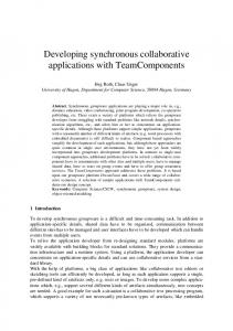
Take the shape shown in Figure!10(a). Assume that this is the design drawn by Designer!1 using a drawing program. This shape is structured by the data structures used to draw the shape and is associated with the original shape in the file, e.g. the dxf file, representing the drawing. The structured shape is also represented as infinite maximal lines and any emergent shape seen by Designer!2 can now be represented. The emergent shape is used to modify the original dxf files and the new shape Figure!10(b) can now be manipulated by both designer. The dxf files are added so that both the original shape and the modified shape are available to both designers.
(a)
(b)
Figure 10. (a) A sixteen-sided figure as input by Designer!1, (b) Two emergent squares as seen by designer!2 and made available t o Designer!1.
This model of emergence can be readily incorporated into the architecture of a synchronous multi-user CAD system as shown in Figure!9.
7
Conclusions
Research and developments in CAD, AI in design, CSCW, and design emergence provide the basis for a multi-user model of a collaborative design environment where a shared workspace is provided to support synchronous design team activity. While the shared visual representation provides the basis for visualising design elements, the shared underlying representation provides a persistent memory of design information, ideas, and intent. Various technologies are now available to explore the implementation and implications of computer-supported collaborative design. While the technology is now accessible and becoming more affordable, how this technology is applied to support synchronous collaborative design is not well developed. Even though it is possible now for a design office to implement networked graphic workstations, within a single location and across cities, the nature of the communication across the network is currently limited to predetermined graphic and non-graphic files and distributed database. These forms of communication do not occur synchronously. Also, shared drawing surfaces are becoming possible. Currently, such systems do not support persistent memory and do not provide the visualisation techniques in current CAD system. How shared drawing surfaces can be extended to accommodate emergent form is still under development. This paper has developed a comprehensive architecture capable of supporting synchronous multi-user collaboration including shape emergence. Preliminary implementations of shared drawing surfaces, shared CAD representations and shape emergence indicate the utility of this architecture. Systems such as the one described in this paper have the potential to alter dramatically the role of CAD in design. CAD can move from being utilised primarily in documentation to early design stage. It can provide facilities not currently available -- designing collaboratively at a distance. Synchronous multi-user CAD system can open up novel ways in which design decisions are made and recorded.
References Bannon, L. and Schmidt, K., 1991. "CSCW: Four Characters in Search of a Context." In J. Bowers and S. Benford (Eds), Studies in Computer Supported Cooperative Work: Theory, Practice and Design. Amsterdam: Elsevier Science, p. 3-16. Benford, S., 1991. "Requirements of Activity Management." In J. Bowers and S. Benford (Eds), Studies in Computer Supported Cooperative Work: Theory, Practice and Design. Amsterdam: Elsevier Science, p. 285-297.
Crowley, T., Milazoo, P., Baker, E., Forsdick, H. and Tomlinson, R., 1990. "MMConf: An Infrastructure for Building Shared Multimedia Applications." In Proceedings of the Conference on Computer-Supported Cooperative Work. New York: ACM, p. 329-342. De La Garza, J. M. and Oralkan, G. M., 1992. "An object space framework for design/construction integration." Building and Environment, Vol. 27, No. 2, p. 243-255. DePaoli, F. and Tisato, F., 1991. "A Model for Real-Time Co-operation." In L. Bannon, M. Robinson and K. Schnidt (Eds), Proceedings of the Second European Conference on Computer-Supported Cooperative Work. Dordrecht: Kluwer Academic, p. 203-217. Dourish, P., 1992. "shdr: a shared drawing program." UK: Rank Xerox EuroPARC. Fenves, S., Flemming, U., Hendrickson, C., Maher, M. and Schmitt, G., 1990. "Integrated Software Environment for Building Design and Construction". Computer Aided Design, Vol. 22, No. 1, p. 27-36. Ganeshan, R., Finger, S. and Garrett, J., 1991. "Representing and reasoning with design intent, in J. S. Gero (ed.), Artificial Intelligence in Design '91. Oxford: Butterworth-Heinemann, p. 737-755. Gero, J. S., 1990. "Design Prototypes: a Knowledge Representation Schema for Design, Artificial Intelligence Magazine, Vol. 11, No. 4, p. 26-36. Gero, J. S. and Yan, M., 1992. "Discovering Emergent Shapes using a Data-Driven Symbolic Model." Amsterdam: Elsevier Science (to appear). Hennessy, P., 1991. "Information domains in CSCW." In J. Bowers and S. Benford (Eds), Studies in Computer Supported Cooperative Work: Theory, Practice and Design. Amsterdam: Elsevier Science, p. 299-311. Ishii, H. and Miyake, N., 1991. "Toward an Open Shared Workspace: Computer and Video Fusion Approach of Teamworkstation, Communication of the ACM, Vol. 34, No. 12, p. 37-50. Law, K. H., Wiederhold, G., Siambela, N., Sujansky, W., Zingmond, D. and Harvinder, S., 1991. "Architecture for Managing Design Objects in a shareable Relational Framework", International Journal of Systems Automation: Research and Applications, Vol. 1, p. 47-65. Lee, J., 1990. "SIBYL: A Tool for Managing Group Decision Rational." In Proceedings of the Conference on Computer-Supported Cooperative Work. New York: ACM, p. 79-92. MacLean, A., Bellotti, V., Young, R. and Moran, T., 1991. "Reaching through Analogy: A Design Rational Perspective on Roles of Analogy." In S. P. Roberston, G. M. Olson and J. S. Olson (Eds), Proceedings of the Conference on Computer-Supported Cooperative Work. New York: ACM, p. 167-172. Mitchell, W., 1989. "Creativity, Emergence and Evolution in Design." In Preprints Modeling Creativity and Knowledge-Based Creative Design. Australia: Design Computing Unit, University of Sydney, p. 263-285.
Pankoke-Babatz, U. (ed.) 1989. Computer Based Group Communication: The AMIGO Activity Model. England: Ellis Horwood. Patterson, J. F., 1990. "Rendezvous: An Architecture for Synchronous Multi-User Applications." In Proceedings of the Conference on Computer-Supported Cooperative Work. New York: ACM, p. 317-328. Poyet, P., Dubois, A. and Delcambre, B., 1990. "Artificial Intelligent Software Engineering in Building Engineering, Microcomputer in Civil Engineering, Vol. 5, No. 3, p. 167-205. Rosenman, M. and Maher, M. L., 1992. "Formal representations for communicating design intent." Australia: Key Centre for Design Quality, University of Sydney, Australia. Sauce, R. and Powell, G. H., 1992. "Object-oriented approaches for integrated engineering design systems, Computing in Civil Engineering, Vol. 6, No. 3, p. 248-265. Smith, H., Hennessy, P. and Lunt, G., 1991. "An Object-Oriented Framework for Modelling Organisation Communication." In J. Bowers and S. Benford (Eds), Studies in Computer Supported Cooperative Work: Theory, Practice and Design. Amsterdam: Elsevier Science, p. 145-158. Sriram, D., Wong, A. and Logcher, R., 1991. "Shared Workspaces in Computer Aided Collaborative Product Development." In Proceedings of the First International Symposium of Building Systems Automation-Integration. Madison: University of Wisconsin, p 1.4.1-1.4.29.
This is a copy of the paper: Maher, M. L., Gero, J. S. and Saad, M. (1993). Synchronous support and emergence in collaborative CAAD, in U. Flemming and S. Van Wyk (eds), CAAD Futures '93, North-Holland, Amsterdam, pp. 455-470.