4 Triazenide, amidinate and guanidinate as new non-innocent ligands. 47 .... Interest in complexes of ânon-innocentâ ligands (NILs) has tremendously increased ...
Synthesis and Electronic Structure Investigation of Ruthenium Complexes Containing Novel Redox-Active Ligands
Von der Fakultät Chemie der Universität Stuttgart zur Erlangung der Würde eines Doktors der Naturwissenschaften (Dr. rer. nat.) genehmigte Abhandlung
Vorgelegt von
Fabian Ehret aus Freiburg
Hauptberichter: Mitberichter: Prüfungsvorsitzender: Tag der mündlichen Prüfung:
Prof. Dr. Wolfgang Kaim Prof. Dr. Dietrich Gudat Prof. Dr. Bernd Plietker 28.05.2014
INSTITUT FÜR ANORGANISCHE CHEMIE DER UNIVERSITÄT STUTTGART 2014
Acknowledgements This work was completed from November 2010 to April 2014 at the Institute of Inorganic Chemistry, University of Stuttgart. First I would like to express my gratitude to my supervisor Prof. Dr. Wolfgang Kaim for giving me the opportunity and the facilities to carry out this thesis work in his group, for all his ideas, discussions, his patience and guidance throughout my research work. I would also like to thank: • Dipl. Chem. Martina Bubrin for solving the crystal structures and Dr. Wolfgang Frey performing the X-ray measurements • Dr. Stanislav Záliš (J. Heyrovský Institute of Physical Chemistry, Department of Electrocatalysis, Prague) for performing the DFT calculations • Dipl. Chem. Vasileios Filippou for helping out with the spectroelectrochemical measurements • Dr. José Luis Priego and Prof. Jiménez-Aparicio for SQUID measurements • Mrs. Barbara Förtsch for elemental analysis and Mrs. Katharina Török and Mrs. Michaela Benzinger for NMR measurements • Dr. Brigitte Schwederski for proofreading the manuscript Finally I would like to thank all the members of Institut für Anorganische Chemie, Universität Stuttgart, especially, the group members of Prof. Kaim’s and Prof. Sarkar’s research group.
Contents
I
Contents 1 Introduction
1
2 Mononuclear complexes with hetero-1,3-diene chelate ligands
7
2.1
Introduction . . . . . . . . . . . . . . . . . . . . . . . . . . . . . . . . . . .
2.2
Results and Discussion . . . . . . . . . . . . . . . . . . . . . . . . . . . . . . 10 2.2.1
2.2.2
2.2.3 2.3
2.4
1
7
Synthesis of the α-azocarbonyl complexes . . . . . . . . . . . . . . . . 10 2.2.1.1
Synthesis of the α-azocarbonyl ligand . . . . . . . . . . . . . 10
2.2.1.2
Synthesis of the donor substituted α-azocarbonyl complex . . 10
2.2.1.3
Synthesis of the acceptor substituted α-azocarbonyl complex
Synthesis of the α-azothiocarbonyl complexes
11
. . . . . . . . . . . . . 11
2.2.2.1
Synthetic view on the elusive α-azothiocarbonyl ligand . . . . 11
2.2.2.2
Synthesis of the donor and acceptor substituted α-azothiocarbonyl complexes . . . . . . . . . . . . . . . . . . . . . . . . . . . 12
Molecular structures . . . . . . . . . . . . . . . . . . . . . . . . . . . 13
H-NMR and EPR spectroscopy of the isolated products . . . . . . . . . . . . 18
2.3.1
Cyclic Voltammetrie . . . . . . . . . . . . . . . . . . . . . . . . . . . 19
2.3.2
EPR spectroelectrochemistry . . . . . . . . . . . . . . . . . . . . . . 20
2.3.3
UV-vis-NIR spectroelectrochemistry . . . . . . . . . . . . . . . . . . . 23
Conclusion . . . . . . . . . . . . . . . . . . . . . . . . . . . . . . . . . . . . 26
3 Dinuclear bis(α-azothiocarbonyl) complexes
27
3.1
Introduction . . . . . . . . . . . . . . . . . . . . . . . . . . . . . . . . . . . 27
3.2
Results and Discussion . . . . . . . . . . . . . . . . . . . . . . . . . . . . . . 31
3.3
3.2.1
Synthesis . . . . . . . . . . . . . . . . . . . . . . . . . . . . . . . . . 31
3.2.2
Molecular Structure . . . . . . . . . . . . . . . . . . . . . . . . . . . 32
3.2.3
1
3.2.4
SQUID suszeptometry . . . . . . . . . . . . . . . . . . . . . . . . . . 36
3.2.5
DFT Calculations . . . . . . . . . . . . . . . . . . . . . . . . . . . . 40
3.2.6
Cyclic Voltammetry . . . . . . . . . . . . . . . . . . . . . . . . . . . 41
3.2.7
EPR spectroelectrochemistry . . . . . . . . . . . . . . . . . . . . . . 42
3.2.8
UV-vis-NIR spectroelectrochemistry . . . . . . . . . . . . . . . . . . . 43
H-NMR and EPR spectroscopy of the isolated products . . . . . . . . 34
Conclusion . . . . . . . . . . . . . . . . . . . . . . . . . . . . . . . . . . . . 45
4 Triazenide, amidinate and guanidinate as new non-innocent ligands
47
4.1
Introduction . . . . . . . . . . . . . . . . . . . . . . . . . . . . . . . . . . . 47
4.2
Results and discussion . . . . . . . . . . . . . . . . . . . . . . . . . . . . . . 49
II
Contents
4.2.1
Synthesis of triazenido ruthenium complexes . . . . . . . . . . . . . . 49 4.2.1.1
Synthesis of triazene precursors . . . . . . . . . . . . . . . . 49
4.2.1.2
Synthesis of triazenido Ru(bpy)2 , Ru(4,4’-EtCO2 -bpy)2 and Ru(pap)2 complexes . . . . . . . . . . . . . . . . . . . . . . 49
4.2.1.3
Synthesis of the p-cymene substituted triazenido ruthenium complexes . . . . . . . . . . . . . . . . . . . . . . . . . . . 50
4.2.2
Molecular structures of the ligand and the triazenido complexes . . . . 51
4.2.3
Cyclic voltammetry of the triazenido ruthenium complexes . . . . . . . 54
4.2.4
EPR spectroelectrochemistry of the triazenido ruthenium complexes . . 56
4.2.5
DFT calculations of the triazenido ruthenium complexes . . . . . . . . 59
4.2.6
UV-vis-NIR spectroelectrochemistry of the triazenido ruthenium complexes . . . . . . . . . . . . . . . . . . . . . . . . . . . . . . . . . . 60
4.2.7
Synthesis of the amidinato and guanidinato ruthenium complexes . . . 63 4.2.7.1
Synthesis of the amidine ligand precursor . . . . . . . . . . . 63
4.2.7.2
Synthesis of the guanidine ligand . . . . . . . . . . . . . . . 64
4.2.7.3
Synthesis of the amidinato and guanidinato complexes with Ru(bpy)2 . . . . . . . . . . . . . . . . . . . . . . . . . . . . 64
4.2.7.4
Synthesis of the amidinato and guanidinato complexes with Ru(p-cym) . . . . . . . . . . . . . . . . . . . . . . . . . . . 65
4.2.8
Molecular structures of the amidinato- and guanidinato- ruthenium complexes . . . . . . . . . . . . . . . . . . . . . . . . . . . . . . . . 66
4.2.9
Cyclic voltammetry of the amidinato and guanidinato ruthenium complexes . . . . . . . . . . . . . . . . . . . . . . . . . . . . . . . . . . 70
4.2.10 EPR spectroelectrochemistry of the amidinato and guanidinato ruthenium complexes . . . . . . . . . . . . . . . . . . . . . . . . . . . . . 72 4.2.11 UV-vis-NIR spectroelectrochemistry of amidinato and guanidinato ruthenium complexes . . . . . . . . . . . . . . . . . . . . . . . . . . . . . 74 4.3
Conclusion . . . . . . . . . . . . . . . . . . . . . . . . . . . . . . . . . . . . 79
5 Amidinyl radical complexes: A new class of near infrared chromophores
80
5.1
Introduction . . . . . . . . . . . . . . . . . . . . . . . . . . . . . . . . . . . 80
5.2
Results and discussion . . . . . . . . . . . . . . . . . . . . . . . . . . . . . . 82
5.3
5.2.1
Synthesis . . . . . . . . . . . . . . . . . . . . . . . . . . . . . . . . . 82
5.2.2
Molecular structure . . . . . . . . . . . . . . . . . . . . . . . . . . . 84
5.2.3
Cyclic voltammetry . . . . . . . . . . . . . . . . . . . . . . . . . . . 88
5.2.4
EPR spectroelectrochemistry . . . . . . . . . . . . . . . . . . . . . . 89
5.2.5
UV–vis–NIR spectroelectrochemistry and DFT analysis . . . . . . . . . 92
Conclusion . . . . . . . . . . . . . . . . . . . . . . . . . . . . . . . . . . . . 95
Contents
III
6 Summary
96
7 Zusammenfassung 8 Experimental section 8.1 Instrumentation . . . . . . . . . . . . . . 8.1.1 EPR spectroscopy . . . . . . . . . 8.1.2 NMR spectroscopy . . . . . . . . . 8.1.3 UV-vis-NIR spectroscopy . . . . . . 8.1.4 UV-vis-NIR spectroelectrochemistry 8.1.5 Cyclic voltammetry . . . . . . . . 8.1.6 X-ray diffraction . . . . . . . . . . 8.1.7 DFT calculations . . . . . . . . . . 8.1.8 Elemental analysis . . . . . . . . . 8.2 Working conditions . . . . . . . . . . . . . 8.2.1 Solvents . . . . . . . . . . . . . . 8.2.2 Chemicals . . . . . . . . . . . . . 8.3 Synthesis . . . . . . . . . . . . . . . . . .
104
. . . . . . . . . . . . .
. . . . . . . . . . . . .
. . . . . . . . . . . . .
. . . . . . . . . . . . .
. . . . . . . . . . . . .
. . . . . . . . . . . . .
. . . . . . . . . . . . .
. . . . . . . . . . . . .
. . . . . . . . . . . . .
. . . . . . . . . . . . .
. . . . . . . . . . . . .
. . . . . . . . . . . . .
. . . . . . . . . . . . .
. . . . . . . . . . . . .
. . . . . . . . . . . . .
. . . . . . . . . . . . .
. . . . . . . . . . . . .
. . . . . . . . . . . . .
113 . 113 . 113 . 113 . 113 . 113 . 113 . 114 . 114 . 114 . 114 . 114 . 114 . 115
9 Appendix 123 9.1 DFT calculated UV–vis–NIR data . . . . . . . . . . . . . . . . . . . . . . . . 123 9.2 Selected crystallographic data . . . . . . . . . . . . . . . . . . . . . . . . . . 126 9.3 Abbreviations . . . . . . . . . . . . . . . . . . . . . . . . . . . . . . . . . . . 133 References
134
1
1 Introduction Interest in complexes of “non-innocent” ligands (NILs) has tremendously increased during the last decades due to their appearance in biological systems1 and their possible application in molecular electronics,2 molecular magnetism,3 light harvesting devices,4 homogeneous catalysis ,5 and group transfer reactions.6 Originally, the concept of ligand “non-innocence” was developed by Jørgensen in 1966 when he pointed out that “ligands are innocent when they allow oxidation states of the central atoms to be defined”7 and therefore denoted all other ligands as “suspect” or “non-innocent”. By means of this definition Jørgenson intended to highlight the oxidation-state ambiguity of complexes containing redox-active transition metals as well as redox-active ligands, which can give rise to “wrong” oxidation-state assignments.8 The assignment of “correct” oxidation states does not only serve the simple role of electron bookkeeping, it also provides information about the physical properties and chemical reactivity related therewith.9 For some ligands the electronic structure of their transition metal complexes in their isolated form (“native state”) is unambiguous, whereas ambiguity arises for other oxidation states.10 Such types of ligands can be labeled as “redox non-innocent”. For a more precise description of redox processes and for highlighting their ambiguity, the expressions ligand/metal centered oxidation/reduction are frequently used. The valence situation in different oxidation states of a complex containing an exemplary enediolate/catecholate non-innocent ligand is illustrated in Figure 1.1.
X
X
R Mn
X
Y
R
R
-e +e
-e
-
-
-
+e
R
Mn+2
X
R
X
Mn+1 R
Y
+e -e -
Y
+e -e -
R
R Mn+1
Mn+2
Y
R
-e +e
-
+e -e -
R
R
Y
= ligand centered process = metal centered process X,Y = S,S; N,N; O,O
X Mn+2
R
Y
M = transition metal with the accesible oxidation states M(n,n+1,n+2)
Figure 1.1: Illustration of non-innocent ligand behavior in various oxidation states.
2
1 Introduction
Although the expression “non-innocent ligand” is widespread, it is important to mention that non-innocence emerges from particular combinations of metal and ligand rather than being an intrinsic property of a ligand. Therefore Ward and McCleverty declared the more appropriate term “non-innocent behavior” for particular coordination situations in preference to “non-innocent ligand”.11 There are many different manifestations12 of non-innocent ligand behavior after electron transfer to or from the NIL, such as structural variations,13 alternations in the acid/base properties, occasionally accompanied by changes of the coordination mode,14 and changes in the reactivity of the complex.15 Such indications can serve either as probe for NIL behavior of already established ligands16 or as basis for the design and development of new NILs. For electronic structure determination of transition-metal coordination compounds an extensive toolbox of physical methods is available.9 As part of this thesis, X-ray crystallography, EPR, NMR, UV-vis-NIR spectroscopy, and SQUID susceptometry are utilized in this regard. To obtain more detailed electrochemical information on the electronic structure of different oxidation states of the compounds, varied experimental setups, combining the spectroscopic methods (EPR/ UV-vis-NIR) with electrochemical methods (=spectroelectrochemistry17 ) are implemented. Since electron transfer to or from redox-active ligands proceeds through single-electron steps, applying a potential to diamagnetic complexes containing this type of ligands necessarily leads to the formation of paramagnetic species. For reasons of predicting physical and chemical properties, e.g. magnetism or reactivity, it is generally of fundamental importance to obtain a deeper insight into the spin density distribution of paramagnetic coordination compounds. In contrast to the mixed situations,18 two borderline classes can be defined: a) the ligand centered radical with mainly ligand contribution to the singly occupied molecular orbital (SOMO) and b) the metal centered paramagnetic complexes with mostly metal contribution to the SOMO. Besides various theoretical methods,19 EPR spectroscopy/spectroelectrochemistry is the most powerful experimental tool for scrutinizing paramagnetic complexes for their spin density distribution.20 EPR spectroscopy provides three sources of information: (1) The isotropic g value: The electron g value has its origin in quantum electrodynamics and is roughly equivalent in utility as the chemical shift is in NMR. Basically the g value is consistent of a second order tensor (matrix), describing a surface in three spatial dimensions. The value of g is therefore anisotropic, i. e. it depends on the relative orientation of the molecule as compared to the magnetic field direction. In solution at room temperature, however, the rotation of small and medium sized molecules is too fast to resolve the different spatial direction on the conventional EPR time scale. Therefore, only the average isotropic g value is
3
observed in solution. The experimental g value is given through the resonance condition in Equation 1.1.
g“
hν µB H
(1.1)
h “ Planck constant, ν “ frequency, µB “ Bohr magneton, H “ magnetic field The deviation of the isotropic g value from the free electron value ge = 2.0023 is attributed to the admixture of higher excited states to the radical ground state, resulting from spin-orbit coupling. The spin-orbit coupling constant increases with the atomic number Z and is hence much larger for heavy transition metal atoms than for the lighter second and third row main group atoms, of which most ligands consist. This behavior results from the relativistic origin of spin-orbit interactions.21 Thus the deviation of the isotropic g value from ge indicates the participation of the transition metal atom/ion at the SOMO. For heavy transition metal centered spins the isotropic g value is frequently unobservable at room temperature due to line broadening based on fast spin relaxation.
g “ ge ´
2 ÿ ÿ ÿ ă Ψ0 |ξk Lik δk |Ψn ąă Ψn |Lij δj |Ψ0 ą “ ge ` ∆gs 3 i n kj En ´ E0
(1.2)
ge “ 2.0023 Ψ0 : MO of the unpaired electron in the ground state Ψn : all other MOs ξk : spin orbit coupling constant Lik{ij : angular momentum operator for AO at nucleuskj Lik δk “ 0except at atomk E0 : energy of a singly occupied molecular orbital (SOMO) En : energies of empty or doubly occupied molecular orbitals (LUMO or HOMO) Equation 1.2 illustrates Stone’s approximation22 for the deviation of the g value as function of the spin orbit coupling constant and the energy difference between the SOMO and all other orbitals. Because the energy differences are in the denominator of Equation 1.2, only the neighbouring energy levels (HOMO and LUMO) need to be considered for significant contributions to ∆g. With respect to the relative energetic position of the three orbitals, however, two different cases, depicted in Figure 1.2, are possible. If the SOMO is closer in energy to the HOMO than to the LUMO (E0 > En ), the g value is greater than ge and vice
4
1 Introduction
versa. Consequently, the relative energy difference of the three frontier orbitals of radical species can be concluded from the deviation from ge of the isotropic g value.
LUMO
SOMO
HOMO g > ge
g < ge
Figure 1.2: Correlation between the relative energy of the frontier orbitals and the deviation of the g value from ge
(2) The g anisotropy: In samples consisting of powders or glassy frozen solutions, the rotation of the molecules is hindered and thus the resonance lines of all three independent spatial directions of the g value appear in the EPR spectrum, conventionally labeled as gx , gy and gz or g1 , g2 and g3 respectively. Out of the three principal g values the g anisotropy ∆g = g1 -g3 and the average g value (Equation 1.3) can be defined. Since the g anisotropy is related to the spin-orbit coupling constant in similar fashion as in (1), it can also be utilized as a probe for the heavy transition metal participation at the SOMO. c “
g1 2 ` g2 2 ` g3 2 3
(1.3)
(3) The hyperfine coupling: The coupling of the unpaired electrons in the complex to nuclei with a non-zero spin I ‰ 0 results in a hyperfine structure of the EPR spectrum. The strength of the coupling is reflected by the hyperfine coupling constant, which is related to the spin density at the coupling nucleus. Hence, the hyperfine coupling constant provides information about the spin density distribution and the coordination environment of a paramagnetic transition metal complex. Unfortunately, the hyperfine structure of transition metal complexes is often insufficiently resolved due to a large number of overlapping lines. A substantial amount of spin density on the metal induces line broadening and may therefore quench the hyperfine structure. To analyze the electronic structure of diamagnetic coordination compounds with NILs, X-ray crystallography is one of the most compelling methods. This approach utilizes the fact that redox-active ligands undergo structural changes by adopting different oxidation states. These variations can be changes of bond length, bond angles, or torsional angles of the NILs. In
5
M N O
E E
E E
+ e- , + e -
e -,
-
e-
+ e- , + e -
e -,
-
e-
+ e- , + e -
2-
M N O
E E
2-
E = O, NR
E E = O, S, NR
- e -, - e E
Figure 1.3: Correlation between the redox state and the structure of some prominent NILs.
this way the structural manifestations of a ligand can be attributed to a specific oxidation state. In Figure 1.3 the structural variations of some prominent NILs are depicted. Besides diamagnetic systems radical ligands can also be identified by their structural properties. This method of identification especially succeeds, when the unpaired electron at the NIL couples antiferromagnetically to a paramagnetic transition metal center or to another radical ligand, and can therefore not be detected by EPR. Since Jørgenson introduced the terms “suspect” or “non-innocent” ligand in 1966, a growing number of well established ligand systems has been attributed this character.23 Moreover, new types of ligands have been designed for the purpose of harnessing their NIL behavior for various applications.24 In this doctoral work, the idea of designing new types of NILs as well as revealing the NIL character of well established ligand systems is pursued. For complexation of NILs, ruthenium(II) precursors including a diverse platform of ancillary ligands have been used. Ruthenium(II) with its d6 electron configuration comprises the advantage of adopting a stable low spin S = 0 ground state in octahedral ligand field. Therefore, ligand centered redox processes will result in an organic radical with S = 1{2 ground state, which can be investigated by EPR without difficulties. Due to the high spin-orbit coupling constant of ruthenium and the corresponding large g anisotropy, metal centered oxidations resulting in ruthenium(III) are easy to distinguish from ligand centered oxidations by EPR.25 A reduction of ruthenium(II) to ruthenium(I) is highly improbable, regarding the used set of ancillary ligands. Chapter 2 describes the synthesis and characterization of the mononuclear ruthenium αazocarbonyl and α-azothiocarbonyl complexes Ru(acac)2 (LO ), Ru(acac)2 (LS ), [Ru(bpy)2 (LO )]PF6 , and [Ru(bpy)2 (LS )]PF6 The complexes were experimentally characterized in various oxidation states by X-ray crystallography, NMR, CV, and EPR/UV-vis-NIR spectroelectrochemistry. Additionally DFT and TD-DFT methods were applied for obtaining an insight into the elec-
6
1 Introduction
tronic structure of the compounds. In Chapter 3 the synthesis and characterization of the dinuclear ruthenium α-azothiocarbonyl complexes ((acac)2 Ru)2 (µ-hte-NNCS-NO2 ) and ((acac)2 Ru)2 (µ-hte-NNCS-CO2 Et) is described. In addition to the experimental methods utilized in Chapter 2, SQUID suszeptometry will be applied for investigation of the complex spin system of the two coordination compounds. The research goal of Chapter 4 is to reveal the non-innocent character of the class of heteroallylic ligands. Therefore the synthesis and mainly EPR spectroelectrochemical investigation of a variety of different substituted triazenido ruthenium complexes is reported. The substitution pattern leading to the desired triazenyl radical complex is then adopted for the preparation of similar amidinato and guanidinato ruthenium complexes, which will then also reveal their non-innocent character. To investigate the strong NIR absorption of the radical complexes UV-vis-NIR spectroelectrochemistry will be applied. In Chapter 5 the idea of utilizing amidinyl radical complexes as chromophores for the near infrared is pursued. For this purpose the synthesis of dimethylaminophenyl substituted amidinato complexes containing different metals as well as coordination modes is described. The influence of the metal and coordination mode on the absorption behavior of the radical ligand will be investigated by using UV–vis–NIR spectroelectrochemistry.
7
2 Mononuclear complexes with hetero-1,3-diene chelate ligands 2.1 Introduction The 4-center hetero-1,3-diene chelate systems belong to the most widely used redox-active ligands in coordination chemistry.1,12,23 For the chelation of metal ions the s-cis conformation of the 1,3-diene structure is required. Represented by the general formulation A=B-C=D, the system can undergo reduction in two single-electron steps to yield ´ A-B=C-D´ , involving a radical anion intermediate (Scheme 2.1). B C A D
+ e-
e-
B C A D
+ e-
e-
A
B C D
A, D = O, S, NR; B, C = N, CR
Figure 2.1: Redox behavior of the hetero-1,3-diene ligand system.
Due to the changes in the bond order, and thus in bond lengths, after electron transfer, the non-innocent behavior of such ligands in complexes with redox-active transition metals can be analyzed via structure analysis. Especially the easily reducible azo bond can serve as precise probe for the oxidation state of the ligand (Figure 2.2). Remarkably, even cases of weak and strong π back-donation can be discriminated in diverse azo ligand containing complexes.13 In addition to the prototypical symmetrical examples, the α-diimines26 (including 2,2’ bipyridine27 and related polypyridyls:28 A, D = NR; B, C = CR’), the α-dicarbonyls29 (including the o-quinone/o-semiquinone/catecholate series:30 A, D = O; B, C = CR’), the α-dithiolenes (A, D = S; B, C = CR’),31 and the tetraazadienes (A, D = NR; B, C = N)32 there are also mixed examples such as the α-iminocarbonyl33 and α-azoimine systems.34 Of the remaining members of the general series (Figures 2.1, 2.3), the reduced α-oxothione function,35 and one α-azocarbonyl example36 have been reported earlier, the latter during attempts to prepare dinuclear compounds of azodicarbonyl ligands. The α-azothiocarbonyl function, however, has
RN NR azo ° ~ 1.25 A
+ e-
e-
RN NR
+ e-
e-
RN NR
2-
(azo)
dihydrazido
° ~ 1.35 A
° ~ 1.45 A
Figure 2.2: Correlation between the bond length and the redox state of the azo bond.
8
2 Mononuclear complexes with hetero-1,3-diene chelate ligands
C NR
C O
C
S
N NR
N RN C
RN
NR
α-diimine
RN
O
α-iminocarbonyl
RN
S
α-iminothiocarbonyl
NR
NR
α-azoimine N
O C
O
O
α-dicarbonyl
O
S
α-oxothione
O
NR
α-azocarbonyl N
S
C
S
S
α-dithiolene
S
NR
α-azothiocarbonyl N N
RN N
RN
NR
tetrazene
Figure 2.3: Possible combination of structure elements for a hetero-1,3-diene ligand.
not been established as bidentate chelate ligand in coordination chemistry to date. This single gap in the series of non-innocent hetero-1,3-diene chelate ligands originates from the difficult accessibility of complexes containing the α-azothiocarbonyl ligand function. While all other ligands in the series can be isolated in free form and can thus react with the appropriate transition metal precursor under straightforward conditions, the α-azothiocarbonyl function is not stable in free form37 and can therefore not be isolated as pure ligand. Electron affinity studies have shown the following energy order of the π* MOs of the carbonyl, the thiocarbonyl and the azo group: π*(C=S) < π*(N=N) < π*(C=O) (Figure 2.4).38 The lowest energy of the π*(C=S) MO can be explained by a stabilization of the orbital resulting from the admixture of a higher lying sulfur 3d orbital. This ranking also indicates the best π-acceptor ability of thiocarbonyl containing hetero-1,3-diene chelate ligands. The ionization energy of the non-bonding orbitals on the heteroatoms follows the same trend as the electron affinity, and therefore reflects the order in electronegativity. With regard to the unique electron acceptor and donor ability of the thiocarbonyl function, it was highly desirable to establish the α-azothiocarbonyl function as ligand in coordination chemistry, despite the challenges in synthesis. To obtain more detailed information about the different nature of the thiocarbonyl versus the carbonyl group, the synthesis and characterisation of the corresponding complexes containing the α-azocarbonyl function were also required for comparison. This chapter describes a synthetic approach for the combination of α-azocarbonyl and αazothiocarbonyl ligands with the electron-rich [Ru(acac)2 ] and the more electron-deficient [Ru(bpy)2 ]2` fragments. In the case of the α-azothiocarbonyl complexes, the ligand was
2.1 Introduction
9
tBu
tBu
tBu
O tBu
S tBu
N N tBu
EA / eV
0.99 0.63
π*
8.20
n
0 0.5) to radical complexes of diamagnetic RuII (with very small g anisotropy), the radical anions can be described as a mixed radical situation [RuIII (acac)2 (L2´ )]´ Ø [RuII (acac)2 (L‚´ )]´ with a considerable metal contribution to the SOMO, confirming the interpretation of the room temperature spectra. The weak resonance line around g = 2.0 in the spectra are assigned to an organic radical impurity, formed during the reduction process. The g anisotropy of ∆g = 0.286 for the cation 3` and of ∆g = 0.169 (calc.) for the cation 9` suggests a predominantly ruthenium(III) situation, according to the formulation RuIII (acac)2 (L0 ). Calculated spin densities on ruthenium of 0.476, 0.742 and 0.49 for 3´ , 3` and 9´ confirm the mixed situation for the anions and the more ruthenium(III) based formulations for the cations. Exemplary plots of the spin density of 3` and 3´ are depicted in Figure 2.19.
22
2 Mononuclear complexes with hetero-1,3-diene chelate ligands
Table 2.3: EPR data for 3, 4, 9, and 10 in various oxidation states from electrochemical generation in CH2 Cl2 /0.1 M Bu4 NPF6 .
ga gb1 gb2 gb3 g1 –g3 d A(14 N)e A(99,101 Ru)e
3´
3`
4`
9´
10`
2.035 2.085 2.045 1.966 0.119 2.032 n.o. n.o.
n.o. 2.220 2.097 1.934 0.286 2.087 n.o. n.o.
2.007 c c c 50 K for 13 and >150 K for 14). This behavior is well reflected in the representation of the magnetic moment with the temperature (Figure 3.12). Thus, at 0.05 and 0.1 Tesla the variation of the magnetic moment with the temperature basically shows a continuous decrease to reach a µeff value of 0.5 µB for 13 and 0.6 µB for 14 which are lower than the expected for one unpaired electron. The magnetic moments at room temperature are
38
3 Dinuclear bis(α-azothiocarbonyl) complexes
(a) 13 at 2 K
(b) 14 at 2 K
Figure 3.10: Representation of the magnetization versus magnetic field for 13 and 14 at 2 K (measured by L. S. Priego).
3.2 µB (at 0.05 T) and 2.8 µB (at 0.1 T) for 13 and 3.4 µB (at 0.05 T) and 3.0 µB (at 0.1 T) for 14 which are close to the expected values for two unpaired electrons per molecule. In these curves, however, maxima at about 80 K and 70 K for 13 and 14, respectively, are observed, suggesting the existence of both ferro- and antiferromagnetic interactions. In contrast, at 1 and 5 Tesla a sudden transition from a paramagnetic state to a diamagnetic one occurs at 57 K and 48 K, respectively for 13. Similar transitions at 144 K and 122 K for 14 are also observed. Thus, at high magnetic field both complexes are diamagnetic at room temperature which is in accordance with the magnetization measurements at 300 K. Moreover, in complex 14 at both magnetic fields the magnetic moment increase from 144 and 122 K to reach a maximum at about 66 K (the exact value of the maximum cannot be established due to the presence of traces of oxygen which are difficult to eliminate due to the weak signal of the compound) and then decreases again until 2 K. At low magnetic fields the continuous increase of the effective magnetic moment µb from 0.5 µb at 2 K to around 3.0 µb at 300 K suggests the presence of a singlet ground state as well as thermally accessible spin states of higher multiplicity which become populated by an increase of the temperature. The drop of the effective magnetic moment to µb = 0 at high magnetic fields and temperatures, however, is still an open question which can not be explained satisfactorily. The idea that the energy gap between the ground and the excited state increases with an increase of the magnetic field does still not explain the inverse temperature dependence of the population of the excited states of higher multiplicity. A further problem is that the experimental magnetic data of 13 and 14 could not be fitted to obtain a value for the exchange coupling constant J, since the the magnetization versus the magnetic field as well as the magnetic susceptibility towards temperature change with the magnetic field is not linear. This results in a different coupling constant at each magnetic field. Magnetic
3.2 Results and Discussion
(a) 13
39
(b) 14
Figure 3.11: Temperature dependence of the magnetic susceptibility of 13 and 14 measured under magnetic fields of 0.05 T (green), 0.1 T (black), 1 T (red) and 5 T (blue) (measured by L. S. Priego).
(a) 13
(b) 14
Figure 3.12: Temperature dependence of the magnetic moment of 13 and 14 measured under magnetic fields of 0.05 T (green), 0.1 T (black), 1 T (red) and 5 T (blue) (measured by L. S. Priego).
40
3 Dinuclear bis(α-azothiocarbonyl) complexes
RuIII
NIL
π
RuIII
NIL
NIL
RuIII
RuIII
NIL
π
NIL
RuIII
π
NIL
excited state (S = 2)
RuIII
NIL
RuIII
π
NIL
RuIII
excited state (S = 1)
ground state (S = 0)
Figure 3.13: Illustration of the possible spin orientation in the ground and the excited states.
transitions induced by a change in magnetic field strength are well known in chemistry,82 but the complicated magnetic behavior of the complexes 13 and 14 is quite unique. 3.2.5 DFT Calculations Geometry optimizations of the neutral complex 13 were performed for 1 A, 3 A and 5 A electronic states using UKS and RKS approaches. The lowest energy state was obtained for unrestricted singlet state with antiparallel spins on the RuIII centers. The calculated singlet – triplet energy difference is 0.17 eV. Geometrical parameters calculated for UKS 1 A state reasonably well describe the experimental structure as indicated in Table 3.9. The DFT calculated spin density in the unrestricted singlet state of 13 is mainly localized on the metal centers and the µ-hte(NNCS)2 bridging ligand (Figure 3.14). The calculations yield absolute values of spin densities of 0.57 and 0.37 for each ruthenium and the µ-hte(NNCS)2 ligand, respectively. All calculations were performed by Dr. Stanislav Záliš.
Figure 3.14: DFT calculated spin densities in the unrestricted singlet state of 13. Blue areas indicate positive and gray areas negative spin densities.
3.2 Results and Discussion
41
Table 3.9: Comparison of experimental and DFT calculated bond lenths (Å) and angles (°) in the Ru-N-N-C-S chelate ring for 13
calc. bond S1-C1 C1-N1 N1-N2 Ru-S1 Ru-N1
exp.
1
A (SB-UKS)
1
A (RKS)
3
A
1.699(7) 1.352(8) 1.331(7) 2.263(2) 1.947(5)
1.713 1.348 1.295 2.242 1.969
1.689 1.341 1.308 2.243 1.920
1.748 1.360 1.286 2.257 2.001
N2-Ru1-S1 82.0(2) C1-S1-Ru1 97.8(2) N1-N2-Ru1 124.3(4) N2-N1-C1 114.0(5) N1-C1-S1 120.9(5)
82.6 97.3 123.5 115.3 120.5
82.3 96.9 123.8 114.5 120.3
83.2 96.7 123.3 116.0 120.6
angle
3.2.6 Cyclic Voltammetry The complexes 13 and 14 were investigated by cyclic voltammetry in CH2 Cl2 /0.1 M NBu4 PF6 at 298 K and 220 K. The experimental data are summarized in Table 3.10 and exemplary plots of the cyclic voltammogram of 13 at 298 K and at 220 K are illustrated in Figure 3.15, respectively. Since the difference of the data for 13 and 14 is negligible, an interpretation based on the influence of nitro versus ethyl ester substitution is not warranted. At room temperature both complexes undergo two reversible reductions at half-wave potentials of around -0.85 V and -1.02 V, respectively, and one irreversible oxidation at an anodic potential of 0.39 V. The irreversibility of the oxidation process of 13 and 14 in comparison with the reversible process of 9 can be explained by the substitution with the strong π-accepting nitro (13) and ethyl ester group (14), respectively. At lower temperature (220 K) the irreversible oxidations split up into two reversible oxidations at half-wave potentials at around 0.36 V and 0.50 V, respectively. The shift of the oxidation of 13 and 14 to lower potentials as compared to 9 is not in accordance with the acceptor substitution of the µ-hte(NNCS)2 ligand function. Facilitated oxidation may result from the delocalization of the unpaired electrons at two α-azothiocarbonyl fragments over an expanded 1,3,5-hexatriene π-system, increasing the energy of the HOMO. Additionally, the π-donating methoxy group in 1-position of the 1,3,5-hexatriene bridge may as well contribute to the negative potential shift of the oxidation for 13 and 14 versus 9. Regarding the positive shift of the reduction potential concerning the dinuclear complexes 13 and 14 versus the mononuclear complex 9, the data are in ac-
42
3 Dinuclear bis(α-azothiocarbonyl) complexes
Table 3.10: Redox potentialsa,b and comproportionation constants pKc qc for 13 and 14.
compound 13 14 a
0 E220K {V
0.48 0.51
0 E298K {V p∆E {V q
0.34 0.37
-0.85 -0.84
-1.02 -1.02
Kc298K (0.17) (0.18)
760 1120
Potentials E 0 {V vs Fc`{0 . b In CH2 Cl2 /0.1 M Bu4 NPF6 /scan rate 100 mV s´1 . c RTlnKc “ nF p∆E q.
(a) 13 at 298 K
(b) 13 at 220 K
Figure 3.15: Cyclic voltammogram of 13 in CH2 Cl2 /0.1 M Bu4 NPF6 at a) 298 K and b) 220 K (scan rate 100 mV s´1 ).
cordance with the substitution pattern of the α-azothiocarbonyl ligand function. The low comproportionation constants of Kc = 760 (13) and Kc = 1120 (14), respectively, suggest a localized (Class II) mixed-valent situation. The low comproportionation constants, caused by weak electronic coupling can be explained through the large metal-metal distance of about 14.5 Å. 3.2.7 EPR spectroelectrochemistry The complexes 13 and 14, EPR silent at 110 K, can be converted into EPR active species through electrochemical oxidation and reduction. Since the oxidation processes of both compounds are only reversible at low temperatures, the electrolysis for obtaining the oxidized species was done at 220 K. The experimental data are summarized in Table 3.11 and exemplary plots of the EPR spectra of 13` and 13´ at 110 K are illustrated in Figure 3.16 and 13 at 10 K in Figure 3.8. The oxidation of 13 and 14 resulted in rhombic EPR signals with large g anisotropies of ∆ g = 0.413 and ∆ g = 0.464, respectively, indicating a predominantly metal localized spin distribution and thus a ligand centered oxidation. After reduction two alternative electronic situations are possible. Either the reduction occurs at the metal and thus results in a RuII /RuIII mixed-valence situation or the reduction occurs at the µ-hte(NNCS)2‚‚2´ bridging ligand and
3.2 Results and Discussion
43
(a) 13´ at 110 K
(b) 13` at 110 K
Figure 3.16: EPR spectra of 13´ and 13` (electrolysis at 220 K) in CH2 Cl2 /0.1 M Bu4 NPF6 at 110 K.
Table 3.11: EPR data for 13, and 14 in various oxidation states from electrochemical generation in CH2 Cl2 /0.1 M Bu4 NPF6 .
g values
13´,a
13b
13`,c
14´,a
14b
14`,a
gb1 gb2 gb3 g1 –g3 d
2.134 2.029 1.932 0.202 2.033
2.146 2.118 1.918 0.228 2.063
2.332 2.117 1.919 0.413 2.129
2.132 2.026 1.930 0.202 2.031
2.151 2.118 1.914 0.237 2.064
2.334 2.123 1.870 0.464 2.118
a
110 K. b 10 K. c 110K (electrolysis at 220 K). d Calculated from = ppg12 ` g22 ` g32 q{3q {2 . 1
results in a radical ligand complex. A rather unlikely situation due to the electronic coupling of the unpaired electrons of the bridging ligand. The reduced species of both complexes are EPR silent at room temperature and show a rhombic signal with a g anisotropy of ∆ g = 0.202 at 110 K, which clearly reveals the expected predominantly but not exclusively metal centered spin distribution. Hence, the conjunction of the EPR data with the low comproportionation constants (Kc = 760 (13), Kc = 1124 (14)) suggest a localized (Class II) mixed-valent situtation.
3.2.8 UV-vis-NIR spectroelectrochemistry UV´vis´NIR spectroelectrochemical measurements on complexes 13 and 14 using an OTTLE cell49 are illustrated in Figure 3.17 and the data are summarized in Table 3.12. Since the spectra of 13 and 14 could not yet be satisfactorily reproduced by TD-DFT calulations due to the complicated spin system and the complexity of the variety of electronic transitions related
44
3 Dinuclear bis(α-azothiocarbonyl) complexes
Table 3.12: UV–vis–NIR data for 13 and 14 in various oxidation states from OTTLE spectroelectrochemistry in CH2 Cl2 /0.1 M Bu4 NPF6 .
complex λmax [nm] (�rM ´1 cm´1 sq 13
218(45 200), 270(43 000), 457(22 000), 598(25 900), 712(21 700)
13´
218(45 200), 270(44 900), 437(17 900), 588(19 000), 729(19 500), 1090(12 300),
132´
218(18 700), 274(49 100), 370(30 400), 432(28 300), 553(18 700), 786(10 600)sh, 938(5 900)sh 218(45 900), 273(35 600), 458(24 700), 597(27 200), 688(22 400)
14 14´ 142´
218(45 900), 273(37 400), 337(27 900), 450(22 200), 593(19 900), 732(19 200), 1090(12 700) 218(42 600), 276(41 000), 420(34 700), 584(21 400), 774(12 500)sh, 938(6 600)sh
therewith, the interpretation of the spectra is based on the calculations of the structurally related complex 9. Since the high energy band of complex 9 at 545 nm is attributed to an MLCT/IL transition, so are the most intensive long wavelength absorptions of 13 and 14 at 712 nm and 688 nm, respectively, attributed to this character. The shift to higher wavelengths may result from a lowering of the ligand LUMOs due to the expanded π system and the strong π acceptor substituents of the bridging ligands containing the α-azothiocarbonyl fragment. After reduction of 13 and 14, in contrast to 9, a band in the near infrared region around 1700 nm (� = 4700 M´1 cm´1 ) appears. This band is assigned to an inter valence charge transfer (IVCT) transition of a RuII RuIII mixed-valent species. The IVCT band intensity and shape of �max ď 5000 M´1 cm´1 and ∆ν1{2 ě 2000 cm´1 suggests a weak electronic interaction (Class II) between the two ruthenium centers.73 After the second reduction a RuII /RuII is formed and as a consequence the IVCT band disappears.
3.3 Conclusion
45
(a) 13 Ñ 13´
(b) 13´ Ñ 132´
(c) 14 Ñ 14´
(d) 14´ Ñ 142´
Figure 3.17: UV–vis–NIR spectroelectrochemical response on stepwise reduction of 13 and 14 in CH2 Cl2 /0.1 M Bu4 NPF6 .
3.3 Conclusion This chapter describes the first synthetic pathway to dinuclear ruthenium complexes with non-innocent α-azothiocarbonyl ligands. The in situ synthesis of the elusive α-azothiocarbonyl ligand system was achieved through a ring opening reaction of acceptor substituted 2-azothiophenes and subsequent C-C coupling. Remarkably, the new type of reaction cascade lead to the formation of a 1,3,5-hexatrienediyl bridged α-azothiocarbonyl ligand chelate function connecting two Ru(acac)2 metal fragments. In contrast to Chapter 2 where donor Ru(acac)2 LS and acceptor substituted [Ru(bpy)2 LS ]` complexes were obtained, with this approach only donor substituted (acac)2 Ruµ-hte(NNCS)2 Ru(acac)2 complexes were accessible. Crystal structure analysis revealed the existence of the bridging ligand in its doubly reduced diradical form µ-hte(NNCS)‚‚2´ , supporting the proposed reaction mechanism which includes an electron 2 transfer from the reducing Ru(acac)2 fragment to the 2-azothiophene, inducing the ring opening of the latter. The obtained system M-NIL-µ ´ π-NIL-M represents a unique coordina-
46
3 Dinuclear bis(α-azothiocarbonyl) complexes
tion arrangement which results in a hitherto unknown type of four-spin system of the type M‚ –‚ µ-BL‚ –‚ M, which displays a complicated magnetic behavior. Based on SQUID suszeptometry measurements a singlet ground state with thermal accessible excited states of higher multiplicity is suggested. DFT calculations based on geometry optimizations including an unrestricted broken symmetry approach confirm the existence of a singlet ground state and assign a singlet – triplet energy difference of 0.17 eV which is, however, much higher than the thermal energy barrier of 0.025 eV at room temperature, and thus doubts the origin of the paramagnetic magnetic behavior. To resolve this dispute a more detailed analysis of the system will be required. Both complexes can be reduced in two reversible one-electron steps, forming a mixed-valent intermediate which is identified by IVCT absorption in the near infrared (e.g. λmax = 1700 nm; � = 4700 M´1 cm´1 )). The low comproportionation constants of Kc = 760 and Kc = 1124 of these intermediates along with the rhombic EPR signal suggest a localized (Class II) mixedvalent situation, favored by the large metal-metal distance of about 14.5 Å. The oxidized forms of the complexes are only accessible at low temperature and exhibit a g anisotropy of more than double the value of the singly reduced species, indicating an even more RuIII localized spin situation. The electronic structure of the experimentally accessible oxidation states is illustrated in a simplified scheme in Figure 3.18.
Ru(III)
NIL
π
NIL
Ru(III)
Ru(III) localized spin
Ru(III)
isolated form
Ru(III)
mixed-valent (Class II)
-e- +e-
Ru(III)
NIL
π
NIL
-e- +e-
Ru(III)
NIL
π
NIL
Figure 3.18: Electronic structure and proposed spin situation of 13 and 14 in various oxidation states.
47
4 Triazenide, amidinate and guanidinate as new non-innocent ligands
4.1 Introduction In the previous chapters the α-azothiocarbonyl ligand, forming five-membered chelate rings upon coordination was established as a new member in the series of the redox-active hetero1,3-diene ligands. An expansion of the ring size to a six-membered chelate coordination type leads to the prominent β-ketaminate and β-diketonate ligands. Their non-innocent character was lately revealed in a more indirect fashion (“hidden non-innocence” or “fractional noninnocence”) .83 A decrease in ring size to a four-membered chelate coordination type results with the well known class of the heteroallylic ligands, which were thought to behave innocently up do date. The bidentate coordination mode and the variation in the chelate ring size by examples of the N-donor ligand types of β-ketaminate, 1,4-diazabutadienes and the amidinates is illustrated in Figure 4.1. Whereas the neutral 1,4-diazabutadienes can undergo two oneelectron reductions the anionic β-ketaminate and amidinate ligands can be expected to under go a one electron oxidation to yield neutral radicals. However, none of the heteroallylic ligands could be detected in its neutral radical coordination mode. Free triazenyl radicals have been reported only as transient species derived from organic azides, showing spin density concentrated on the peripheral nitrogen centers.84 M R N R
M N R
R N
R
R
M N R R
R N
N R R
R A
B
C
Figure 4.1: The chelating coordination modes of the β-diketonate (A), 1,4-diazabutadiene (B) and amidinate (C) ligands.
The goal of this chapter is to reveal the potential for non-innocent character of different kinds of heteroallylic ligands in complexes with ruthenium. It will be shown that oxidation of RuII complexes with heteroallylic ligands can result either in a RuIII (L´ ) or in a RuII (L0 ) situation (Figure 4.2). The ambivalent behavior was achieved by the tuning the electronic structure of the complexes, and by variation of the substituents at the heteroallylic as well as ancillary ligands. Therefore, the triazenido, amidinato and guanidinato forms were used, since their substitution pattern can be easily varied. Other potentially non-innocently behaving
48
4 Triazenide, amidinate and guanidinate as new non-innocent ligands
RuIIILn N R
E
N R
RuIILn N R
E
-e-
N
RuIILn
R N R
E
N R
E = N: triazenido; E = CR: amidinato; E = CNR2: guanidinato
Figure 4.2: The different pathways for the oxidation of a RuII complex with triazenido, amidinato or guanidinato ligands.
ligands containing heteroatoms of the second row are the nitro/nitrito (N or O binding) and the carboxylato ligands. Besides their potentially redox-active character discussed in this capter, heteroallylic ligands have been investigated intensely regarding various properties. As promising alternatives for cyclopentadienyl-based ligands the N-centered donor ligands have made a comeback in various fields of coordination and organometallic chemistry.85 Compared to the cyclopentadienylbased ligands their electronic and steric properties can more easily be tuned by varying the substituents at the N and C atoms, since synthetic routes are much more convenient. In addition to the chelating coordination mode, this type of ligand can also function as bridging ligand for di- or polynuclear metal complexes. The short distance between the coordinating heteroatoms provides an ideal environment for the implementation of short metal-metal distances and thus for the stabilization of metal-metal multiple bonds.86 The preference for chelating versus bridging coordination mode mainly depends on the size of the substituents on the central carbon atom (for amidinato, guanidinato and carboxylato ligands). Another important feature of the triazenido, amidinato and guanidinato ligands is their high basicity, with pKa values of the corresponding protonated forms of between pKa = 5–13,87 which furnishes a strong donor character to these ligands. Due to the better mesomeric stabilization of the corresponding cationic form, the guanidines are the strongest bases in this series. Compared to the amidinato and the guanidinato ligand the triazenido ligand is less electron donating due to a lower charge density on the coordinating N-atoms,88 resulting in a more electrophilic character of the coordinated metal.
4.2 Results and discussion
49
4.2 Results and discussion At the beginning of this project the conditions under which a triazenyl, amidinyl or guanidiny radical complex could be stabilized were not known. Therefore, ruthenium complexes containing different ancillary ligands as well as different substituted heteroallylic ligands had to be scrutinized in this regard. Since the synthesis of various substituted triazenes is more convenient than that of the corresponding amidines and guanidines, the initial project focused on the synthesis of different substituted ruthenium triazenido complexes. The aim was to create an adequate substitution pattern for the stabilization of triazenyl radical ligands, which could then be transferred to the synthesis of ruthenium containing amidinato and guanidinato complexes to obtain the corresponding radical complexes after one electron oxidation.
4.2.1 Synthesis of triazenido ruthenium complexes 4.2.1.1 Synthesis of triazene precursors The triazenes H15, H16 and H17 were synthesized according to a one step literature procedure89 starting from the corresponding aniline. The triazene H18 was synthesized according to a literature procedure90 starting from tert-butylazide and tert-butyllithium (Figure 4.3). NH2
1. HCl(aq)/NaNO2 2. NaOAc R
H N R
N
N R
H15: R = 3-CF3 H16: R = H H17: R = 4-OMe N3 +
Li
1. Et2O 2. H2O
H N
N
N
H18
Figure 4.3: Synthesis of the triazene ligands.
4.2.1.2 Synthesis of triazenido Ru(bpy)2 , Ru(4,4’-EtCO2 -bpy)2 and Ru(pap)2 complexes The metal precursors Ru(bpy)2 Cl2 91 (bpy = 2,2’-bipyridine), Ru(4,4’-EtCO2 -bpy)2 Cl2 92 and α-Ru(pap)2 Cl2 93 (pap = 2-phenylazopyridine) were synthesized according to literature procedures. AgBF4 was used for activation of the metal precursors by chloride abstraction.
50
4 Triazenide, amidinate and guanidinate as new non-innocent ligands
BF4 N N
Cl Ru Cl N
1. AgBF4 2. H(L), Et3N
N
R N Ru N N N R N
N
N
R = 3-CF3-C6H5: 19BF4 R = C6H5: 20BF4 R = 4-OMe-C6H5: 21BF4 R = tBu: 22BF4 BF4 N N
N Ru
N N
Cl Cl
N N
1. AgBF4 2. H(17), Et3N
OMe
N N
Ru N N
N
N N
N OMe 24BF4
Figure 4.4: Synthesis of the bis(bpy), bis(4,4’-EtCO2 -bpy) and bis(pap) substituted triazenido ruthenium complexes.
4.2.1.3 Synthesis of the p-cymene substituted triazenido ruthenium complexes For reasons of favoring a ligand centered oxidation of the complex, p-cymene (p-cym) substituted ruthenium complexes containing the deprotonated 1,3-bis(4-methoxyphenyl)triazene (17´ ) were prepared with various ancillary ligands. The ruthenium precursor [Ru(p-cym)Cl2 ]2 is comercially available. Ru(p-cym)Cl(17) (25) was synthesized by reacting the comercially available precursor [Ru(pcym)Cl2 ]2 under deprotonation with H17. AgBF4 was used for activation of the metal precursors by chloride abstraction. Cl Cl Ru
Ru
1. AgBF4 2. H17/Et3N
Ru Cl N
Cl Cl
N
N
MeO
OMe 25
Figure 4.5: Synthesis of the p-cymene substituted triazenido complexes.
4.2 Results and discussion
51
Ru(p-cym)CN(17) (26) was synthesized by reacting 25 with an excess of KCN in acetonitrile under reflux. The π-accepting CN´ ligand was introduced to withdraw electron density via backbonding from the RuII to favor the triazenido oxidation.
Ru Cl N
N
N
MeO
Ru CN
KCN N
-KCl OMe
N
N
MeO
OMe
25
26
Figure 4.6: Synthesis of the p-cymene substituted triazenido complexes.
[Ru(p-cym)MeCN(17)]SbF6 (27SbF6 ) was synthesized by reacting 25 with one equivalent of AgSbF6 in acetonitrile under reflux. AgSbF6 was used for chlorid abstraction to obtain a better crystalisation behavior of the resulting complex. The neutral acetonitril ligand was introduced to increase the positive charge at RuII to favor the triazenido oxidation. SbF6 Ru Cl N
N
MeO
N
N
-AgCl OMe
25
Ru N
MeCN/AgSbF6
N
N
MeO
OMe 27SbF6
Figure 4.7: Synthesis of the p-cymene substituted triazenido complexes.
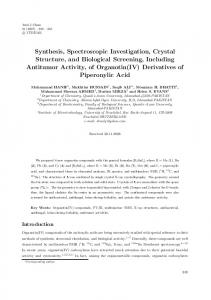
4.2.2 Molecular structures of the ligand and the triazenido complexes The ligand precursor H17 as well as the complexes 21ClO4 and 27SbF6 could be crystallized for X-ray structure analysis (Figure 4.9–4.10). Crystallization procedures were as follows. H17: slow evaporation of a solution of H17 in CH2 Cl2 /n-hexane; Complex 21ClO4 : slow diffusion of Et2 O into a solution of 21PF6 and NBu4 ClO4 in MeCN; 27SbF6 : slow diffusion of Et2 O into a solution of 27SbF6 in MeCN. The data of the important bond lengths and angles are summarized and compared with those of the uncoordinated triazene H17 in Table 4.13. The N-N bond lengths of the free triazene do not represent the typical even bond order, since the N2-N3(H) bond distance of 1.316(2) Å is too short for an ordinary N-N single bond („ 1.35 Å) and the N1-N2 bond of 1.293(2) Å is too long for N=N („ 1.25 Å), indicating N-N bond orders of around 1.5 caused by a partial charge delocalization. After deprotonation and coordination the changes in the N-N bond lengths are only marginal. The deviation of
52
4 Triazenide, amidinate and guanidinate as new non-innocent ligands
Table 4.13: Selected bond lengths (Å) and angles (°) in the Ru-N1-N2-N3 chelate ring.
bond (Å)
21ClO4
27SbF6
H17
Ru1-N1 Ru1-N3 N1-N2 N2-N3
2.072(2) 2.078(2) 1.312(3) 1.316(3)
2.090(3) 2.058(3) 1.314(4) 1.313(4)
1.293(2) 1.316(2)
103.9(2)
102.6(3)
112.8(1)
angle (°) N1-N2-N3
Figure 4.8: Molecular structure of H17 in the crystal.
the N1-N2-N3 angle in the complex (103°) from the angle of the free triazene (113°) can be explained by a distortion due to chelate coordination to the metal center.
4.2 Results and discussion
Figure 4.9: Molecular structure of 21` in the crystal of 21ClO4 .
Figure 4.10: Molecular structure of 27` in the crystal of 27SbF6 .
53
54
4 Triazenide, amidinate and guanidinate as new non-innocent ligands
4.2.3 Cyclic voltammetry of the triazenido ruthenium complexes All ruthenium triazenido complexes (Figures 4.4–4.7) were investigated by cyclic voltammetry in 0.1 M CH2 Cl2 /NBu4 PF6 at a scan rate of 100 mv/s. Exemplary plots of the cyclovoltammograms are illustrated in Figure 4.11. The redox potentials are summarized in Table 4.14. The Ru(bpy)2 complexes 19BF4 –22BF4 exhibit one irreversible reduction which is attributed to a process at the bpy ligand, since the triazenido ligands are not reducible. On substitution of both bpy ligands by the acceptor substituted 4,4’-EtCO2 -bpy or the even stronger π-acceptor ligand pap, the resulting complexes 23BF4 and 24BF4 show two reversible reductions, one at each of the acceptor ligands.94 Nevertheless, the aim of generating a stable triazenyl radical complex through a one electron oxidation places a higher importance on the oxidation processes which are discussed in the following. By varying the substituents at the triazenido ligand from electron withdrawing (R = 3-CF3 -C6 H5 , 19BF4 ) to electron donating (R = 4-OMe-C6 H5 , 21BF4 ) the oxidation potentials shift gradually towards lower potentials from E1{2 = 0.45 V to E1{2 = -0.10 V. After the replacement of the π-donating/σ-accepting 4-methoxyphenyl substituent by a purely σdonating tert-butyl substituent the oxidation potential decreases further to a value of E1{2 = -0.12 V for 22BF4 . The fact that the N,N’-dialkyl complex 22BF4 exhibits only one oxidation leads to the conclusion that the triazenido ligand participates in the second oxidation of complexes 20BF4 and 21BF4 . On substitution of the bpy ligands by the stronger π-accepting 4,4’-EtCO2 -bpy and pap ligands the oxidation potential increases to the higher values of E1{2 = 0.12 V for 23BF4 and E1{2 = 0.33 V for 24BF4 , respectively. All p-cymene containing complexes exhibit one reversible and one irreversible oxidation. In Figure 4.11e a cyclovoltammogram of 27SbF6 is depicted in which i) only the first and ii) both oxidations are displayed, since Table 4.14: Redox potentialsa of triazenido ruthenium complexes.
a
complex
E0298 / V vs Fc`{0
19BF4 20BF4 21BF4 22BF4 23BF4 24BF4 25 26 27SbF6
0.45 0.22 -0.10 -0.12 0.13 0.33 0.24 0.26 0.39
1.18 b 0.63
0.91b 0.95b 0.91b
-1.88c -1.90c -2.06c -1.43 -0.70
-1.80 -1.38
In CH2 Cl2 /0.1 M Bu4 NPF6 /scan rate 100 mV s´1 . b Anodic peak potential. c Cathodic peak potential.
4.2 Results and discussion
55
(a) 19BF4
(b) 20BF4
(c) 21BF4
(d) 24BF4
(e) 27SbF6 Red: only first oxidation; Black: first and second oxidation.
Figure 4.11: Cyclic voltammetry of the triazenido ruthenium complexes in CH2 Cl2 /0.1 M Bu4 NPF6 (scan rate 100 mV s´1 ).
the first oxidation is only fully reversible if the second oxidation is not monitored. For the pcymene containing complexes the effect on the oxidation potential by exchangeing a π-donating chlorido (25) with a π-accepting cyano ligand (26) is marginal, with a shift of only ∆ E = 0.02 V to higher potential. An exchange of the chlorido ligand by the neutral acetonitrile ligand, however, shifts the oxidation potential from E1{2 = 0.24 V (24) to E1{2 = 0.39 V (27SbF6 ).
56
4 Triazenide, amidinate and guanidinate as new non-innocent ligands
This effect can be explained by an increase of the overall charge of the complex from 0 to +1, resulting in a higher oxidation potential. Because the influence of the substitution pattern of the complexes towards the oxidation potential is not in correlation with the influence towards the nature of the oxidation (ruthenium vs triazenido), EPR spectroelectrochemistry needs to be applied to all complexes. The results are discussed in the following section. 4.2.4 EPR spectroelectrochemistry of the triazenido ruthenium complexes Cyclic voltammetry experiments revealed at least one reversible oxidation for each of the triazenido complexes. To get an insight into the nature of the oxidation process (ruthenium vs triazenido) the oxidized forms of the triazenido ruthenium complexes were investigated by EPR spectroscopy. Literature data suggest that the reductions of complexes 23BF4 and 24BF4 occur at the strongly π-accepting ancillary ligands 4,4’-EtCO2 -bpy or pap, respectively.94 Their reduction processes shall therefore not be discussed in this section. Exemplary plots of the EPR spectra of 192` , 212` , 242` , 25` and 262` are depicted in Figures 4.12 and 4.13. The EPR data as well as the potentials of the first oxidation of all complexes are summarized in Table 4.15, indicating that the oxidation potentials and the g values are not in correlation. The rhombic EPR signal of complex 192` with a g anisotropy of ∆g = 0.451 at 110K indicates a predominantly ruthenium centered spin situation RuIII (L´ ). By exchanging the electron withdrawing 3-CF3 with an electron donating 4-OMe (212` ) group, the g anisotropy decreases to a value of ∆g = 0.100 at 110 K, suggesting a mixed situation with approximately Table 4.15: EPR and electrochemical data of the mono-oxidized triazenido ruthenium complexes.a
complex 192` 202` 212` 222` 232` 242` 25` 26` 272`
E1{2
giso (298 K)
0.45 0.22 -0.10 -0.12 0.13 0.33 0.24 0.26 0.39
2.194 2.104 2.048 2.154 2.032 2.011 2.011b 2.011c 2.007d
g1 , g2 , g3 (110 K)
g1 ´g3
2.350, 2.185, 2.087, 2.273, 2.056,
0.451 0.231 0.100 0.047 0.061 < 0.02 < 0.02 < 0.02 < 0.02
2.273, 2.142, 2.064, 2.243, 2.039, e e e e
1.899 1.954 1.987 1.938 1.995
Potentials E1{2 versus Fc`{0 from cyclic voltammetry in CH2 Cl2 /0.1 M Bu4 NPF6 ; EPR data from electrolysis in CH2 Cl2 /0.1 M Bu4 NPF6 ; X band results. b Hyperfine splitting: 0.66 mT (2 x 14 N), 0.55 mT (1 x 99,101 Ru). c Hyperfine splitting: 0.66 mT (2 x 14 N), 0.37 mT (1 x 99,101 Ru). d Hyperfine splitting: 0.199 mT (1 x 14 N), 0.629 mT (2 x 14 N), 0.127 mT (6 x 1 H), 0.109 mT (2 x 1 H), 0.080 mT (2 x 1 H), 0.094 mT (4 x 1 H), 0.272 mT (1 x 99,101 Ru). Linewidth: ∆B1{2 = 0.07 mT. e g anisotropy not resolved. a
4.2 Results and discussion
57
(a) 192` at 110 K
(b) 202` at 110 K
(c) 212` at 298 K
(d) 242` at 298 K
Figure 4.12: EPR spectra of the oxidized triazenido complexes in CH2 Cl2 /0.1 M Bu4 NPF6 .
Figure 4.13: EPR spectrum of 272` in CH2 Cl2 /0.1 M Bu4 NPF6 at 298 K.
58
4 Triazenide, amidinate and guanidinate as new non-innocent ligands
Figure 4.14: Illustration of the correlation between the substitution pattern of the triazenido complexes and the isotropic g value. Red: RuIII (L´ ) complex; green: mixed radical situation RuIII (L´ ) Ø RuII (L‚ ); blue: triazenyl radical complex RuII (L‚ ).
equal spin density on ruthenium and the triazenido ligand RuIII (L´ )ØRuII (L‚ ). To hamper RuII oxidation and favor the oxidation of the triazenido ligand, the weakly π-accepting bpy ligands were substituted with the strongly π-accepting 4,4’-EtCO2 -bpy or pap ligands, respectively. The influence of replacement is nicely shown in the EPR spectra of complexes 232` and 24` which exhibit a g anisotropy of ∆g < 0.02 at 110K and isotropic g values of around 2.011 at 298 K. The isotropic g values suggest predominant ligand contributions to the SOMO RuII (L‚ ). The metal contribution, however, is still high enough to cause a line broadening which quenches the hyperfine structure in the spectra. Since a hyperfine structure resulting from the coupling to N and H atoms of the triazenyl radical ligand would be a clear evidence for the desired ligand centered oxidation, a different set of ancillary ligands had to be introduced. The new strategy included the replacement of the π-accepting/σ-donating 4,4’-EtCO2 -bpy or pap ligand through the π-accepting but not σ-donating p-cymene ligand. This approach was thought to decrease the electron density at RuII center and thus inhibit its oxidation. For reasons of synthetic accessibility the first p-cymene substituted complex investigated (25` ) included a π-donating chlorido ligand. This substitution had no effect on the isotropic g value of g = 2.011 at 298 K, however, a poorly resolved quintet with coupling constants of A1 = 0.66 mT (2 x 14 N) and A2 = 0.55 mT (1 x 99,101 Ru) emerged in the spectrum. The quintet structure of triazenyl radicals can be explained by the symmetry of the SOMO which has a node located at the central N atom, diminishing spin density and therefore its coupling constant. An
4.2 Results and discussion
59
exchange of the π-donating chlorido ligand with a π-accepting cyano ligand had no influence on neither the g value nor on the hyperfine structure. The replacement of the chlorido ligand with a neutral π-accepting acetonitril ligand (272` ), however, resulted in a decrease of the g value to g = 2.007 and the appearance of a well resolved hyperfine structure. The spectrum could be simulated (Figure 4.13) using the coupling constants displayed in the footnote in Table 4.15. An increase of the overall charge around the ruthenium center facilitates a ligand centered oxidation and explains the ligand substitution effect of cyano versus acetonitrile. The observation of a low g value close to that of the free electron with ge = 2.0023 along with the hyperfine splitting is a clear evidence for an almost purely ligand centered oxidation resulting in a triazenyl radical complex. Complex 272` is the first example of a metal stabilized triazenyl radical. The remarkable correlation between the structures of the complexes and the isotropic g value is visualized in the diagram of Figure 4.14. 4.2.5 DFT calculations of the triazenido ruthenium complexes To add theoretical insight into the electronic structures of the triazenido complexes in their singly oxidized forms the spin densities of complexes 192` , 212` and 272` were calculated using DFT methods. All calculation were performed by Dr. Stanislav Záliš on a G09/PBE0/6311G(d)/PCM-CH2 Cl2 level of theory. Plots of the spin densities are depicted in Figure 4.15 and the data are summarized in Table 4.16 The calculations confirm the experimental results of the EPR spectroelectrochemistry. Whereas a spin density at ruthenium of 72.6 % for 192` indicates a predominantly rutheniumcentered radical RuIII (L´ ), the spin density at ruthenium of only 0.4 % for 272` clearly confirms the existence of a triazenyl radical complex RuII (L‚ ). The ruthenium spin density of 18.5 % for 212` is interpreted as a mixed orbital situation in which the radical exhibits metal as well as ligand character RuIII (L´ ) Ø RuII (L‚ ).
Figure 4.15: Plots of the DFT calculated (G09/PBE0/6-311G(d)/PCM-CH2 Cl2 ) spin densities of representative triazenido ruthenium complexes.
60
4 Triazenide, amidinate and guanidinate as new non-innocent ligands
Table 4.16: DFT calculated (G09/PBE0/6-311G(d)/PCM-CH2 Cl2 ) spin densities of representative triazenido ruthenium complexes.
ρ Ru ρ N1 ρ N2 ρ N3 ρ R1 ρ R2
192`
212`
272`
0.726 0.136 -0.078 0.136 0.056 0.056
0.185 0.251 -0.149 0.251 0.240 0.240
0.004 0.243 -0.157 0.243 0.336 0.336
4.2.6 UV-vis-NIR spectroelectrochemistry of the triazenido ruthenium complexes UV´vis´NIR spectroelectrochemical measurements of all triazenido ruthenium complexes using an OTTLE cell49 are illustrated in Figures 4.21–4.17 and summarized in Table 4.21. The spectra are discussed briefly based on EPR results and literature reports, since no TD-DFT calculations for an exact band assignment are available. For the characterization of RuIII or triazenyl radical complexes only the oxidation processes are of interest and are therefore discussed exclusively. The Ru(bpy)2 complexes 19` –21` exhibit a low energy transition around 465 nm, which are at a similar energy level as the ruthenium-based MLCT transitions in [Ru(bpy)3 ]2` (455 nm).95 Through an exchange of the phenyl groups at the triazene with the stronger electron donating tert-butyl group (22) the MLCT band shifts to lower energy of 537 nm. Upon ruthenium centered oxidation of 19` and for 21` a hypsochromic shift of the MLCT band is expected, however, a band in the near infrared region at 960 nm for 192` and 740 nm 212` emerges. This low energy band may be explained by the allowance of an LMCT transition from the triazenido ligand to the t2g orbitals of ruthenium after oxidation. Complexes 202` and 212` , with their more ligand-centered spin density exhibit a low energy band at even higher wavelengths of around 1030 nm, which might indicate a predominantly intra ligand charge transfer (ILCT) transition. In agreement with MLCT transitions around 550 nm for related amidinato complexes containing the Ru(pap)2 fragment,96 complexes 23` and 24` exhibit a low energy transition at 560 nm and 530 nm, respectively. The predominantly ligand centered oxidation results in a bathochromic shift of these MLCT transitions to 750 nm (23` ) and 895 nm (24` ), which may also be attributed to a mixed LMCT/ILCT transition. The MLCT transitions of the Ru(p-cym) triazenido complexes occur around 415 nm and are therefore higher in energy than the MLCT transitions of the complexes containing the stronger π-accepting nitrogen-based heterocyclic ligands. Oxidation of the p-cymene complexes results in the appearance of a near infrared absorption band. Due to the triazenyl radical character
4.2 Results and discussion
61
of the singly oxidized complexes, as evidenced by EPR spectroscopy, these low energy bands are attributed mainly to an ILCT. The near infrared ILCT transitions are of remarkably high intensities and narrow line widths: 872 nm (� = 26 700 M´1 cm´1 ; ∆1{2 = 1100 cm 1 ) for + + 25 , 880 nm (� = 29 800 M´1 cm´1 ; ∆1{2 = 845 cm 1 ) for 26 and 900 nm (� = 34 000 M´1 + cm´1 ; ∆1{2 = 715 cm 1 ) for 272 , pointing to small geometry differences between ground and excited state. Table 4.17: UV–vis–NIR data for 19–27 in various oxidation states from OTTLE spectroelectrochemistry in CH2 Cl2 /0.1 M Bu4 NPF6 .
complex λmax [nm] (� (M´1 cm´1 )) 19`
240(29 700), 290(46 200), 330(21 300), 460(14 600), 480(4 700)
192`
245(36 300), 315(33 000), 340(18 700), 965(3 600)
20`
243(35 700), 287(46 000), 343(23 600), 475(21 800), 630(1 100)
20
243(35 700), 271(39 000), 365(24 600), 510(14 100), 626(600), 1055(7 600)
21`
247(34 500), 290(56 900), 336(23 300), 470(21 000), 576(3 900), 660(2 000)
212`
222`
247(29 200), 285(42 300), 406(21 800), 536(16 900), 573(44 100), 681(5 600), 748(9 000), 1020(5 800) 247(29 200), 285(42 300), 390(18 900), 504(21 000), 573(20 600), 687(11 100), 751(24 200), 990(4 700), 1370(500) 243(21 900), 294(27 100), 350(11 100), 405(6 300), 473(6 400), 535(7 500), 680(600) 263(23 800), 303(20 200), 314(19 600), 350(5 500), 384(3 100), 740(2 900)
23`
230(44 700), 310(66 100), 465(30 400), 565(9 300), 756(2 000)
232`
230(44 700), 305(53 700), 410(26 000), 534(22 900), 573(50 500), 681(4 600), 756(15 500), 970(7 100), 1250(1 900) 243(29 900), 306(28 900), 437(19 700), 533(10 800), 625(2 500)
2`
213` 22`
24` 242` 25 25` 26 26` 27` 272`
229(24 200), 275(21 200), 350(27 800), 379(27 800), 538(28 000), 569(51 000), 730(7 000), 817(8 600), 897(21 300) 217(18 500), 252(20 600), 314(14 400), 410(23 300) 217(18 500), 250(13 000), 340(12 200), 560(32 300), 542(55 100), 775(13 200), 872(26 800) 248(14 200), 320(9 600), 422(18 400) 245(8 300), 334(10 700), 511(26 700), 541(48 800), 710(5 400), 790(9 600), 880(29 800) 247(21 450), 306(11 300), 410(20 600) 247(12 400), 324(12 00), 524(27 300), 560(37 600), 718(3 000), 821(6 600), 903(33 900)
62
4 Triazenide, amidinate and guanidinate as new non-innocent ligands
(a) 19` Ñ 192`
(b) 20` Ñ 202`
(c) 21` Ñ 212`
(d) 22` Ñ 222`
(e) 23` Ñ 232`
(f) 24` Ñ 242`
Figure 4.16: UV–vis–NIR spectroelectrochemical response on oxidation of triazenido ruthenium complexes in CH2 Cl2 /0.1 M Bu4 NPF6 .
4.2 Results and discussion
63
(a) 25Ñ 25`
(b) 26Ñ 26`
(c) 27` Ñ 272`
Figure 4.17: UV–vis–NIR spectroelectrochemical response of triazenido ruthenium complexes on oxidation in CH2 Cl2 /0.1 M Bu4 NPF6 .
4.2.7 Synthesis of the amidinato and guanidinato ruthenium complexes Since the synthetic approach utilized for the triazenido complexes resulted in the observation of RuIII as well as triazenyl radical complexes, this strategy was adopted for the synthesis of amidinato and guanidinato complexes which can exhibit a RuIII , a mixed and a ligand centered radical (amidinyl, guanidinyl) complex after oxidation. HL stands for the neutral amidine or guanidine, respectively, as precursor for the deprotonated amidinato or guadinato ligand L´ and not for the corresponding amidinium or guanidinium cations.
4.2.7.1 Synthesis of the amidine ligand precursor The aminidine ligand precursor H28 was synthesized according to a literature procedure97 by reacting p-anisidine with ethyl ortho-acetate at 140 °C for 3 h.
64
4 Triazenide, amidinate and guanidinate as new non-innocent ligands
NH2 OEt EtO OEt
+
H N
N
cat. TsOH MeO
OMe
OMe H28
Figure 4.18: Synthesis of the 4-methoxy substituted amidine ligand 28.
4.2.7.2 Synthesis of the guanidine ligand Due to the methoxy substituents the guanidine ligand precursor H29 can not be directly obtained from corresponding thiourea in a one step reaction with permanganate. Therefore, a published three step procedure98 starting from the corresponding thiourea was used for the synthesis of the protonated guanidine ligand. MeO
MeO
S
N
MeI
S
NH
MeO
HI
.
NH
MeO
1. Me2NH 2. Na2CO3
N N
NH
MeO
NH
MeO H29
Figure 4.19: Synthesis of the 4-methoxy substituted guanidine ligand H29 precursor.
4.2.7.3 Synthesis of the amidinato and guanidinato complexes with Ru(bpy)2 A strong base for the deprotonation of the aminidine and guanidine ligands had to be used to obtain good yields for the Ru(bpy)2 amidinato and guanidinato complexes. Potassium hydroxide instead of triethylamine was used and the solvent was changed from acetone to ethanol. Otherwise, the reaction procedure was the same as for the Ru(bpy)2 triazenido complexes. After purification using column chromatography the complexes [Ru(bpy)2 (28)]PF6 ((30)PF6 ) and [Ru(bpy)2 (29)]PF6 ((31)PF6 ) were obtained as pure reddish brown solids.
4.2 Results and discussion
65
PF6 OMe N N
Cl Ru Cl N
1. AgPF6 2. HL, KOH
N N N
N
Ru
N N
E
N OMe 30PF6: E = C-CH3 31PF6: E = C-N(CH3)2
Figure 4.20: Synthesis of the complexes (30)PF6 and (31)PF6 .
4.2.7.4 Synthesis of the amidinato and guanidinato complexes with Ru(p-cym) During the first attempts of synthesis it was observed that the p-cymene containing ruthenium amidinato and guanidinato complexes are not as stable as their triazenido analogs, meaning that the complexes could not be purified with column chromatography. Therefore, different reaction conditions, leading to less side products and to a better purification of the product had to be worked out. For that purpose a mixture of [Ru(p-cym)Cl2 ]2 and the aminidine/guanidine was stirred with an excess of potassium carbonate in acetone at ambient temperature for 3 h. After the precipitate was filtered through celite the solvent of the filtrate was removed and the remaining solid was recrystallized from CH2 Cl2 /n-hexane to obtain the complexes Ru(p-cym)Cl(28) 32 and Ru(p-cym)Cl(29) 33 as pure orange solids. Cl Cl Ru
Ru
HL/K2CO3
Ru Cl N
Cl Cl
E
N
MeO
OMe 32: E = C-CH3 33: E = C-N(CH3)2
Figure 4.21: Synthesis of the complexes 32 and 33.
As described above, in order to obtain a triazenyl radical after oxidation the chlorido ligand of complex 27SbF6 had to be substituted with an acetonitrile ligand. Unfortunately, the corresponding complexes [Ru(p-cym)MeCN(28)]SbF6 and [Ru(p-cym)MeCN(29)]SbF6 could not be isolated due to their lack of stability and poor crystallization behavior. Therefore a different monodentate π-acceptor ligand had to be found, to provide a higher stability and a better crystallization behavior. For synthetic reasons the chlorido ligand was substituted with a pyridine (py) ligand, since the chloride anion can easily be abstracted with TlPF6 in a solution
66
4 Triazenide, amidinate and guanidinate as new non-innocent ligands
of 32 or 33 in pyridine. TlPF6 was used instead of AgSbF6 because AgCl is highly soluble in pyridine. In contrast to the complexes 32 or 33 the complexes [Ru(p-cym)(py)(28)]PF6 (34PF6 ) and [Ru(p-cym)(py)(28)]PF6 (35PF6 ) are stable enough to be purified by column chromatography. PF6 Ru Cl N
E
N
MeO
N
-TlCl OMe
32: E = C-CH3 33: E = C-N(CH3)2
Ru N
pyridine/TlPF6
E
N
MeO
OMe 34PF6: E = C-CH3 35PF6: E = C-N(CH3)2
Figure 4.22: Synthesis of the complexes 34PF6 and 35PF6 .
4.2.8 Molecular structures of the amidinato- and guanidinato- ruthenium complexes Complexes 30OTf, 31PF6 , 32, 33 and 34BPh4 could be crystallized for X-ray structure analysis (Figure 4.23–4.27). Crystallization procedures were as follows. Complex 30OTf: slow diffusion of Et2 O into a solution of 30PF6 and NBu4 OTf in MeCN; 31PF6 : slow diffusion of Et2 O into a solution of 31PF6 in MeCN; 32: slow evaporation of a solution of 32 in CH2 Cl2 /n-hexane; 33: slow evaporation of a solution of 33 in CH2 Cl2 /n-hexane; 34BPh4 : slow diffusion of nhexane into a solution of 34PF6 and NBu4 BPh4 in CH2 Cl2 . The data of the important bond lengths and angles are summarized and compared with those of the uncoordinated amidine H37 and guanidine H5 C6 -N1-C1(CR2 )-N2(H)-C6 H5 99 (Gu-1) in Table 4.18. In all complexes the N1-C1 and N2-C1 bond lengths of around 1.33 Å for the amidinato and 1.34 Å for the guanidinato complexes lie between the N-C single and N=C double bond lengths for the uncoordinated amidine and guanidine, respectively, indicating a delocalization of the negative charge over the N1-C1-N2 chelate rings in the complexes. The deviation of the N1-C1-N2 angles in the complexes of around 108° from the free amidine or guanidine angle of around 123° can be explained by the distortion due to chelate coordination to the metal center. A correlation between the basicity of the ligands (amidinato < guanidinato) and the N1-Ru/N2-Ru bond lengths is not observed. In comparison with the triazenido ruthenium complexes the angles of the N-E-N (E = N, CR, CNR2 ) fragments in the ligands of the amidinate- and guanidinate-ruthenium complexes as well as of the free ligands are larger with ∆? « 10° for the free ligands and ∆? « 5° for the complexes, respectively. This observation is in agreement with the valence shell electron pair repulsion (VSEPR) rules,100 which attribute
4.2 Results and discussion
67
Table 4.18: Bond lengths (Å) and angles (°) in the Ru-N1-C1-N2 chelate ring in comparison with the free ligand.
bond (Å) Ru1-N1 Ru1-N2 N1-C1 N2-C1
30OTf 2.102(3) 2.107(3) 1.323(6) 1.334(6)
31PF6
32
33
34PF6
H37
Gu-1
2.122(2) 2.088(4) 2.073(2) 2.122(2) 2.089(2) 2.092(4) 2.131(2) 2.089(2) 1.344(2) 1.339(6) 1.337(2) 1.324(3) 1.295(3) 1.291(9) 1.354(1) 1.324(6) 1.342(2) 1.334(2) 1.360(3) 1.40(1)
angle (°) N1-N2-N3
108.3(4) 109.6(2) 106.6(4) 108.2(2) 109.6(2) 122.0(2) 124.1(6)
Figure 4.23: Molecular structure of 30` in the crystal of 30OTf.
a higher steric demand to the lone pair at the N2 atom of the triazenido ligand than to the C1-C2 bond in the amidinato or the C1-N3 bond in the guanidinato ligand.
68
4 Triazenide, amidinate and guanidinate as new non-innocent ligands
Figure 4.24: Molecular structure of 31` in the crystal of 31PF6 .
Figure 4.25: Molecular structure of 32 in the crystal.
4.2 Results and discussion
Figure 4.26: Molecular structure of 33 in the crystal.
Figure 4.27: Molecular structure of 34` in the crystal of 34PF6 .
69
70
4 Triazenide, amidinate and guanidinate as new non-innocent ligands
4.2.9 Cyclic voltammetry of the amidinato and guanidinato ruthenium complexes All ruthenium amidinato and guanidinato complexes were investigated by cyclic voltammetry in 0.1 M CH2 Cl2 /NBu4 PF6 at a scan rate of 100 mv/s. Exemplary plots of the cyclovoltammograms are illustrated in Figure 4.28. The redox potentials are summarized in Table 4.19. The Ru(bpy)2 amidinato and guanidinato complexes 30PF6 and 31PF6 exhibit two reversible oxidations each. It is striking that the oxidation potential for the amidinato complex is higher than the potential of the guanidinato complex (∆ E = 0.12 V), whereas for the Ru(p-cym)(py) complexes 34PF6 and 35PF6 an inverse behavior is observed (∆ E = 0.15 V). Since the first oxidation of 30PF6 and 31PF6 is expected to occur at the ruthenium, the potential shift indicates a better stabilization of RuIII for the guanidinato complex. This observation is in agreement with the higher basicity of the guanidinato (29) versus the aminidinato (28) ligand. As the oxidation of 34PF6 and 35PF6 is expected to occur at the ligand, the inverse potential shift indicates that the guanidinato ligand is more difficult to oxidize than the corresponding amidinato ligand. The lower oxidation potential of E1{2 = 0.13 V for 32 as compared to E1{2 = 0.20 V for 33 also suggests a predominantly ligand centered oxidation for both compounds. As result of a substitution experiment a ligand participation was attributed to the second oxidation process of the triazenido complex 21PF6 . Consequently, this character is also assigned to the second oxidation of the complexes 30PF6 and 31PF6 . A comparison with the oxidation potentials of the corresponding triazenido ruthenium complexes leads to the conclusion that the triazenido ligand stabilizes the RuIII oxidation state as well as the amidinato ligand, since both Ru(bpy)2 complexes 21PF6 and 30PF6 exhibit the same potential of E1{2 = -0.10 V. Regarding the ligand-centered oxidation, the potential of the ruthenium triazenido complex 27SbF6 lies between the potentials of the amidinato (34PF6 ) and the guanidinato ruthenium complex (35PF6 ), suggesting a trend of the oxidation potentials of the ligands according to: amidinato < triazenido < guanidinato. The different ancillary ligands pyridine and acetonitrile, however, may bias this conclusion, because the stronger π-accepting acetonitrile ligand might lead to an increase of the oxidation potential of the triazenido complex 27SbF6 . Therefore, the position of the triazenido and the amidinato ligand might rather be reversed in this series. To resolve this dispute, EPR spectroelectrochemistry was applied to the amidinato and guanidinato ruthenium complexes.
4.2 Results and discussion
71
Table 4.19: Redox otentialsa,b of triazenido, amidinato and guanidinato ruthenium complexes in comparison.
complex 30PF6 31PF6 32 33 34PF6 35PF6 Potentials vs Fc0{` . versible process. b
b
E0298 / V 0.72 0.64 0.82c 0.87c 1.00c 1.19c
-0.10 -0.22 0.13 0.20 0.35 0.50
complex
E0298 / V
21PF6
-0.10
25
0.24
25SbF6
0.39
In CH2 Cl2 /0.1 M Bu4 NPF6 /scan rate 100 mV s´ 1.
c
Anodic peak potential of irre-
(a) 30PF6
(b) 31PF6
(c) 34PF6
(d) 35PF6
Figure 4.28: Cyclic voltammetry of amidinato and guanidinato complexes in CH2 Cl2 /0.1 M Bu4 NPF6 (scan rate 100 mV s).
72
4 Triazenide, amidinate and guanidinate as new non-innocent ligands
4.2.10 EPR spectroelectrochemistry of the amidinato and guanidinato ruthenium complexes Cyclic voltammetry experiments resulted in a reversible oxidation for each of the amidinato and guanidinato complexes. To get an insight in the nature of the oxidation process (ruthenium vs amidinato/guanidinato), the oxidized forms of complexes 30PF6 –35PF6 were investigated by EPR spectroscopy. Exemplary plots of the EPR spectra of 302` –352` are depicted in Figure 4.29–4.30. The EPR data as well as the potentials of the first oxidation of all complexes are summarized in Table 4.20, indicating that the oxidation potentials and the g values are not in direct correlation. The EPR spectra at 110 K of the Ru(bpy)2 complexes show rhombic signals with a g anisotropy of ∆g = 0.312 for 302` and ∆g = 0.580 for 312` , respectively, indicating a predominantly ruthenium centered spin situation RuIII (L´ ). For the p-cymene/chloride containing singly oxidized complexes with isotropic g values of g = 2.028 at 298 K and a g anisotropy of around ∆g = 0.04 a mixed orbital radical situation RuIII (L´ )ØRuII (L‚ ) is observed. Whereas the isotropic spectra at 298 K do not exhibit a hyperfine structure, the low temperature spectra of 32` shows a coupling to the coordinating N atoms (quintet, 2 x A(14 N) = 0.88 mT) in the direction of g1 , indicating a considerable spin density at the amidinato ligand. Through the substitution of the chlorido with the neutral π-accepting pyridine ligand a poorly resolved but evident hyperfine structure emerges in the room temperature spectrum of 342` (quintet, 2 x A(14 N) = 0.53 mT, 1 x A(99,101 Ru) = 0.69 mT, ∆B1{2 = 0.80 mT) and 352` (quintet, 2 x A(14 N) = 0.59 mT, 1 x A(99,101 Ru) = 0.61 mT, ∆B1{2 = 0.75 mT). The occurrence of a hyperfine structure in conjunction with the relative low isotropic g values of g = 2.015 confirms the expected ligand centered radical situation RuII (L‚ ). Additionally, the presence of a ligand centered radical is confirmed by the DFT calculated (ADF/PBE0) spin density (Figure 4.30c) for 342` of 1.3 % at ruthenium and 16.4 % at each of the coordinating N atoms.The complexes 342` and 342` are the first examples of metal stabilized amidinyl and guanidinyl radicals, respectively. In comparison to the triazenyl radical complex 272` , the EPR spectra of the amidinyl and guanidinyl radical complexes 342` and 352` exhibit a less resolved hyperfine splitting due to a larger linewidth and higher ruthenium coupling constant, indicating a somewhat higher spin density at the ruthenium center. Additionally, the g anisotropy of ∆g = 0.100 for the Ru(bpy)2 triazenido complex 212` indicates a mixed-orbital situation, whereas the corresponding amidinato and guanidinato complexes 302` and 312` clearly exhibit rutheniumcentered spin. The EPR results thus attribute a lower oxidation potential to the triazenido ligand than to the corresponding amidinato and guanidinato ligands when coordinated to ruthenium and therefore alter the series for the oxidation potential, based on cyclic voltammetry results, to: triazenido < amidinato « guanidinato.
4.2 Results and discussion
73
(a) 302` at 110 K
(b) 312` at 110 K
(c) 32` at 298 K
(d) 32` at 110 K
(e) 33` at 298 K
(f) 33` at 110 K
Figure 4.29: EPR spectra of the amidinato ruthenium and guanidinato ruthenium complexes in CH2 Cl2 /0.1 M Bu4 NPF6 .
74
4 Triazenide, amidinate and guanidinate as new non-innocent ligands
Table 4.20: EPR data for 302` –352` from electrochemical generation in CH2 Cl2 /0.1 M Bu4 NPF6 .
complex 302` 312` 32` 33` 342` 352`
E1{2
giso (298 K)
g1 , g2 , g3 (110 K)
g1 ´g3
-0.10 -0.22 0.13 0.20 0.35 0.50
2.136 2.136 2.028 2.028 2.015c 2.015d
2.250, 2.180, 1.938 2.424, 2.250, 1.844 2.032, 2.007, 2.000c 2.051, 2.012, 2.004 2.033, 2.010, 2.007 2.026, 2.009, 2.008
0.312 0.580 0.032 0.047 0.026 0.018
(a) EPR of 342` at 298 K
(b) EPR of 352` at 298 K
(c) Spin density of 342`
Figure 4.30: a) and b): EPR spectra of 342` and 352` in CH2 Cl2 /0.1 M Bu4 NPF6 at 298 K. c) DFT (ADF/PBE0) calculated spin density of 342` .
4.2.11 UV-vis-NIR spectroelectrochemistry of amidinato and guanidinato ruthenium complexes UV´vis´NIR spectroelectrochemical measurements of complex 30PF6 –35PF6 using an OTTLE cell are illustrated in Figures 4.31–4.33 and summarized in Table 4.21. The spectra of complex 30n` –33n` and 35n` are only briefly discussed based on EPR results and literature, since no TD-DFT calculations for an exact band assignment are available. The
4.2 Results and discussion
75
transitions of complex 34n` , however, were calculated by TD-DFT (CAM-B3LYP/PCM/6311G(d)) methods. All calculations were performed by Dr. Stanislav Záliš. The TD-DFT assignment for the transitions of 34n (n = 0, +1) listed in Table A.2 in the appendix. Although amidinato and guanidinato complexes containing the Ru(bpy)2 are not represented in the literature, the absorption band of the bpy substituted complexes in the visible region at 550 nm are assigned to MLCT transitions. The bathochromic shift of ∆λ = 83 nm compared to the corresponding triazenido complex (21` ) can be explained through an increase in energy of the Ru(d) orbitals due to the stronger electron donating amidinato and guanidinato ligands. A similar effect is observed for complex 22` containing a tert-butyl substituted triazenido ligand (see Section 4.2.6). After the RuII /RuIII oxidation both complexes exhibit an absorption band in the near infrared at 1060 nm for 302` and at 950 nm for 312` , which are attributed to an LMCT (L´ Ñ RuIII ) character. Oxidation to the dication, associated with a RuIII (L‚ ) rather than a RuIV (L´ ) configuration results in an additional near infrared band of higher intensity at 890 nm (� = 12800 M´1 cm´1 ) for 303` . The most intense band in the visible and near infrared region of complex 313` appears at 645 nm (� = 12800 M´1 cm´1 ). Due to the absence of TD-DFT calculations and the complex electronic structure of 303` and 313` no reasonable band assignment can be made, explaining the disparity in the spectra. All four p-cymene containing complexes display intense absorption bands around 300 nm accompanied by a shoulder at around 420 nm. Because the band at 300 nm is also present in the spectra of the bpy containing complexes, an ILCT character (π Ñ π ˚ ) is assigned to this band. The shoulder at 420 nm probably represents a MLCT transition (RuII Ñ π ˚ -pcymene/π ˚ -L). Upon oxidation of the chlorido containing amidinato complex 32 two bands in the near infrared region at 776 nm and 1010 nm emerge. The corresponding guanidinato complex displays a similar absorption pattern, however, the low energy band at 1500 nm (� = 12 800 M´1 cm´1 ) is less intense and extends across the accessible near infrared region. As EPR spectroscopy reveals a relatively high ligand contribution to the SOMO of 32` and 33` , the long-wavelength bands are attributed a predominantly ILCT character. A chlorido/pyridine ligand exchange results in the occurrence of a remarkably intense and narrow near infrared absorption band at 1010 nm (� = 25 500 M´1 cm´1 ; ∆1{2 = 1170 cm- 1) for complex 342` . TD-DFT calculations attribute this transition to a βHOMO–βLUMO ILCT excitation with slight LMCT admixture. The theoretical result also confirms the interpretation of the corresponding triazenido complex 272` . The frontier orbitals, mainly contributing to the low energy transition are depicted in Figure 4.32, and the data for all calculated transitions of complex 34n` (n = 1, 2) are summarized in Table A.1. Compared to the triazenyl and amidiyl radical complexes 272` and 342` the guanidinyl radical complex 352` displays a significantly different spectrum in which the long-wavelength absorption is shifted to lower energy of 1570 nm. Additionally, a strong decrease in intensity (� = 1 300 M´1 cm´1 ) along with a significant line broadening is observed. The bathochromic shift may be explained by an extended spin
76
4 Triazenide, amidinate and guanidinate as new non-innocent ligands
Table 4.21: UV–vis–NIR data for amidinato ruthenium and guanidinato ruthenium complexes in various oxidation states from OTTLE spectroelectrochemistry in CH2 Cl2 /0.1 M Bu4 NPF6 .
complex λmax [nm] (� (M´1 cm´1 )) 30`
247(34 500), 295(57 200), 364(22 800), 490(6 500), 550(8 400), 710(5 000)sh
302`
247(34 500), 295(57 200), 400(11 900), 710(6 800), 1060(4 200)
303`
247(34 500), 282(42 700), 360(11 000), 430(7 400), 720(10 200), 890(12 800)
312`
247(40 9000), 293(54 700), 351(18 000), 404(11 000), 505(7 600), 550(10 900), 700(1 600)sh, 950(4 500) 247(44 300), 289(50 200), 390(10 600), 720(4 000), 950(4 400)
303`
247(44 300), 289(45 800), 377(8 100), 645(15 200), 950(5 000), 1170(2 100)
32
243(7 000), 318(7 400), 420(500)
32`
285(12 200), 388 (23 400), 776(16 600), 1010(9 600)
33
238(33 200), 298(41 000), 427(3 300)
`
31
33
226(32 800), 289(29 300), 530(3 700), 835(4 700), 1400(1 500)sh
34`
238(18 400), 297(21 800), 424(1 800)
342`
260(14 900), 400(21 300), 422(21 300), 730 (7 500), 1010(25 500)
`
35
235(15 900), 290(21 400), 404(1 900)
352`
235(14 900), 265(14 700), 350(850), 472(2 500), 800(3 600), 1570(1 300)
`
delocalization of the guanidinyl radical ligand radical over the CN3 fragment, resulting in a decrease of the HOMO–LUMO gap. A low energy barrier of the rotation around the C1-N3 axis could cause the extreme line-broadening effect.
4.2 Results and discussion
77
(a) 30` Ñ 302`
(b) 302` Ñ 303`
(c) 31` Ñ 312`
(d) 312` Ñ 313`
(e) 32Ñ 32`
(f) 33Ñ 33`
Figure 4.31: UV–vis–NIR spectroelectrochemical response on oxidation of the amidinato ruthenium and guanidinato ruthenium complexes in CH2 Cl2 /0.1 M Bu4 NPF6 .
78
4 Triazenide, amidinate and guanidinate as new non-innocent ligands
Figure 4.32: UV–vis–NIR spectroelectrochemical response on oxidation of 34+ in CH2 Cl2 /0.1 M Bu4 NPF6 , and frontier orbitals involved in the near infrared transition at 1010 nm.
Figure 4.33: UV–vis–NIR spectroelectrochemical response on oxidation of of 35+ in CH2 Cl2 /0.1 M Bu4 NPF6 .
4.3 Conclusion
79
4.3 Conclusion The research goal of this Chapter was to reveal the potential non-innocent character of the class of heteroallylic ligands, hitherto thought to behave innocently. For reasons of simple synthetic modification and variation of the electronic structure, the triazenido ligand system was utilized as a model to work out the conditions under which this type of ligand system is prone to behave non-innocently. Accordingly, by systematic variation of the electronic structure of the ligand system itself as well as of the ancillary ligands a continuum was established for the oxidation of the triazenido ruthenium complexes, ranging from a) a ruthenium-centered spin situation Ln RuIII (RNNNR´ ) species via b) orbital-mixed systems Ln RuIII (RNNNR´ ) Ø Ln RuII (RNNNR‚ ) to c) triazenyl radical complexes Ln RuII (RNNNR‚ ).101 The desired preference for the ligand-centered as opposed to the ruthenium-centered oxidation was eventually achieved by substitution of the triazenido ligand (RNNNR´ ) with electron donating methoxy groups and using the π-accepting and non σ-donating p-cymene as ancillary ligand (Ln ). This successful approach was then extended to amidinato and guanidinato ruthenium complexes, which could also be detected in the different valence isomeric forms a)–c) after oxidation by EPR spectroelectrochemical and DFT methods. Remarkably, no electronic tuning of the heteroallylic ligand was needed in case of the amidinato and guanidinato complexes. To analyse the tendency of the different ligand systems in their chelating coordination modes to be oxidized, EPR spectroelectrochemistry was found to provide the most precise information, since cyclic voltammetry experiments cannot discriminate between ligand- and metal-centered processes. Based on EPR data, which revealed a slightly more ligand-centered spin density in the triazenyl radical complex than in the amidinyl and guanidinyl radical complexes, a series for the magnitude of the oxidation potentials of the ruthenium coordinating ligands was established: triazenido < amidinato « guanidinato. In addition to their novelty, the triazenyl and amidinyl radical complexes were found to exhibit a strong absorption in the near infrared region of the electromagnetic spectrum, which is attributed to a predominantly ILCT transition of the radical ligand. This remarkable feature makes such types of complexes attractive for applications in various NIR absorbing devices. For that purpose, these promising systems are further investigated in the following Chapter.
80
5 Amidinyl radical complexes: A new class of near infrared chromophores
5 Amidinyl radical complexes: A new class of near infrared chromophores 5.1 Introduction Among different other results was shown in Chapter 4 that triazenyl- and amidinyl ruthenium radical complexes exhibit electronic absorptions in the near infrared (NIR, 800 – 2500 nm, 12500 – 4000 cm´1 ) region. These bands lie between 800 – 1000 nm and are of high intensitiy and narrow linewidth. Based on this striking observation it was thus planned to extend this promising approach to the development of new NIR chromophores of lower oxidation potentials, simplifying the isolation of the oxidized NIR active form and therefore allow a more detailed characterization as well as a possible application in NIR absorbing devices. Additionally, a shift to lower oxidation potentials of the NIR absorbing radical ligand precursor is expected to be accompanied by a low-energy shift of the electronic transition possibly extending as far as the telecommunication window (1310 nm or 1550 nm).102 NIR dyes have been intensively investigated due to their wide range of applications, for example in optoelectronic devices,103 solar cells,104 optical communication,105 as well as chemosensors and probes.106 Among these NIR absorbers there are purely organic molecules, the most
π∗L NIR (ILCT) NIR (IVCT)
π∗L π ∗L
(1) dM
NIR (MLCT)
NIR (ILCT)
(2) dM (3)
dM dM
πL
πL NIR (ILCT) πL
a)
b)
c)
Figure 5.1: Concepts for transition metal complexes absorbing in the NIR.
5.1 Introduction
81
representative being cyanines107 and boron-dipyrromethene,108 polymers,109 and coordination compounds of different nuclearity.110 For transition metal complexes absorbing in the NIR several concepts exist:111 a) extended ligand π-systems which exhibit a low HOM–LUMO gap and therefore allow low-energetic LMCT or ILCT transitions, respectively; b) the presence of radical ion ligands with a low energy gap between SOMO and LUMO or SOMO and the highest doubly occupied orbital, respectively; c) mixed valency accompanied by IVCT transitions (Figure 5.6). Chromophores containing π conjugated 4-dimethylaminophenyl (DMAP) groups of different charge (neutral donor, cationic acceptor) have been well employed in conventional dyestuff technology. The most prominent of the triphenylmethyl class of compounds are malachite green [CPh(DMAP)2 ]` = 36a and crystal violet [C(DMAP)3 ]` = 36b (Figure 5.2) with their large absorptivity in the visible region of the electromagnetic spectrum (λmax = 621 nm (36a) and 590 nm (36b), � = 105 00 M´1 cm´1 (36a) and 112 00 M´1 cm´1 (36b)).112 R
N
N 36a: R = H 36b: R = DMAP
Figure 5.2: Molecular structure of malachite green 36a and crystal violet 36b.
Inspired by this ubiquitous pigment class, it was intended to incorporate the DMAP group into the amidinyl radical system described previously to facilitate the oxidation of the amidinato ligand precursor and to decrease the energy gap between the frontier orbitals through extension of spin distribution. The effect of the ligands coordination mode as well as the influence of the coordinating metal on the NIR absorption behavior was to be investigated by synthesizing DMAP- amidinyl complexes with various metals, known to exhibit coordination environments different from from the piano stool structure of the Ru(p-cym)XL2 system described in Chapter 4.
82
5 Amidinyl radical complexes: A new class of near infrared chromophores
5.2 Results and discussion
5.2.1 Synthesis
The dimethylaminophenyl (DMAP) substituted amidine ligand H37 was synthesized according to the previously described procedure for the methoxy substituted amidine ligand H28 through the reaction of N,N-dimethyl-p-phenylenediamine with ethyl orthoacetate. To simplify the purification process of the desired product H37, the starting material N,N-dimethylp-phenylenediamine was sublimed under inert atmosphere before use. The raw product was purified using column chromatography and recrystallized from CH2 Cl2 /n-hexane to obtain white crystals. NH2 OEt EtO OEt
+
H N
N
cat. TsOH Me2N
NMe2
NMe2 H37
Figure 5.3: Synthesis of the DMAP substituted amidinate H37.
The complex Ru(p-cym)Cl(37) (38) was synthesized according to the procedure for the synthesis of 32 through the reaction of the precursor [Ru(p-cym)Cl2 ]2 with H37 under deprotonation. After the reaction was completed, the mixture was filtered through celite and the solvent was removed. To obtain a pure product the complex was recrystallized from CH2 Cl2 /n-hexane to afford red crystals. Cl Cl Ru
H37/K2CO3
Ru Cl
Ru N
Cl
N
Cl Me2N
NMe2 38
Figure 5.4: Synthesis of the Ru(p-cym)Cl aminidinato complex (38).
The oxidized form of 38 was obtained as 38PF6 through the reaction of 38 with ferrocenium hexafluorophosphate (FcPF6 ) as oxidation agent for 1 h at room temperature in CH2 Cl2 . To obtain a pure product the complex was recrystallized from CH2 Cl2 /n-hexane to afford black crystals.
5.2 Results and discussion
83
PF6 Ru Cl N
Ru Cl
FcPF6
N
Me2N
N NMe2
N
Me2N
NMe2
38
38PF6
Figure 5.5: Synthesis of the oxidized form 38PF6 .
For the synthesis of the palladium and the platinum complexes 39 and 40 the metal precursors PdCl2 (MeCN)2 and PtCl2 (dmso)2 were reacted under the same conditions (Cs2 CO3 , acetone, 60 °C, 15 h). Both complexes were purified using column chromatography. Despite equal reaction conditions, two different products were obtained. Whereas the palatinum complex exhibits a square planar coordination mode, the palladium complex shows a paddle wheel structure, where two palladium centers are bridged by four amidinato ligands. NMe2
Me2N N
N Pt so )2
Me2N
N
NH
Cs2CO3, acetone
Pt C
l2 (
dm
N Me2N
NMe2
39
N
NMe2
Cl
Pd
Me2N (M
2
Me2N
eC
N
N
N)
N
2
Me2N
NMe2
N
Pd Pd N Me2N
N
N
N
Me2N
NMe2 NMe2
40
Figure 5.6: Synthesis of the square planar platinum amidinato complex 39 and the paddle wheel structured palladium complex 40.
84
5 Amidinyl radical complexes: A new class of near infrared chromophores
5.2.2 Molecular structure The amidine ligand H37 as well as the complexes 38, 38PF6 , 39 and 40 could be crystallized for X-ray structure analysis (Figures 5.8–5.12). The experimental as well as the DFT calculated (G09/PBE0/6-311G(d)) data of the important bond lengths and angles of 38 and 38PF6 are summarized in Table 5.22. Crystallization procedures were as follows. H37, 38, 39 and 40: slow evaporation of a solution of H37, 38, 39 or 40, respectively in CH2 Cl2 /n-hexane; 38PF6 : slow diffusion of n-hexane into a solution of 38PF6 in CH2 Cl2 . While the differences in bond lengths and angles between the uncoordinated amidine H37 and the amidinato ligand were already discussed in Chapter 4, the focus of attention in this chapter lies in the structural differences of 38 and its oxidized form 38PF6 . Whereas the N1-Ru1-N2 bite angle of 61.5° and the N1-C1-N2 chelate angle of 107.4° remain basically unchanged, significant variations are observed in the C-NMe2 and C-NC(CH3 )N bond lengths of 1.41 Å in 38 vs 1.37 Å in 38` . These differences were confirmed by DFT calculations, illustrating a tendency towards formation of a p-quinonoid structure113 in the oxidized form. With disregard of the octet rule114 the spin distribution of the DMAP substituted amidinyl radical complex 38` is thus represented by two major resonance structures (Figure 5.7), illustrating the expected high spin densities at the DMPA (A) as well as at the ruthenium coordinated nitrogen atoms (B). RuLn
RuLn N
N
N
N
N (A)
N
N
N (B)
Figure 5.7: Major resonance structures of the amidinyl radical ligand in 38` .
In the cases of the palladium and platinum complexes, crystal structure analysis reveals a square planar coordination mode with small bite angles of ?(N1-Pt-N2) = 62.8(2)° and chelate angles of ?(N1-C1-N2) = 108.2(6)° in 39 in contrast to the paddle wheel structure of 40 with much wider chelate angles of ?(N1-C1-N2) = 120.7(3)°. Whereas the structural data of 39 with Pt-N bond lengths of 2.05 Å are in accordance with literature data,115 the Pd(II)-Pd(II) bond length of 2.543 Å in 40 is significantly shorter than a proposed Pd(II)Pd(III) bond (2.597 Å) with bond order of 1.5116 but also longer than a Pd(III)-Pd(III) bond of 2.391 Å.117 The structural difference between the palladium and platinum complexes nicely reflects the typical behavior of large metals binding to ligands with small bite angles.
5.2 Results and discussion
85
Table 5.22: Experimental and DFT calculated (G09/PBE0/6-311G(d)) bond lengths (Å) and angle (°) in 38 and 38PF6 .
38 bond Ru1-N1 Ru1-N2 N1-C1 N1-C3 N2-C1 N2-C11 N3-C6 N4-C14 angle N1-C1-N2 N1-Ru1-N2
38PF6
exp.
calc.
exp.
calc.
2.071(2) 2.114(2) 1.323(4) 1.402(4) 1.333(4) 1.408(4) 1.409(4) 1.407(4)
2.092 2.094 1.326 1.394 1.327 1.386 1.387 1.387
2.084(2) 2.093(2) 1.345(3) 1.383(3) 1.339(3) 1.382(3) 1.370(4) 1.364(3)
2.092 2.097 1.335 1.369 1.334 1.370 1.370 1.357
exp.
calc.
exp.
calc.
107.4(2) 61.50(9)
107.8 61.6
105.8(2) 61.65(8)
106.2 61.2
Figure 5.8: Molecular structure of H37 in the crystal.
86
5 Amidinyl radical complexes: A new class of near infrared chromophores
Figure 5.9: Molecular structure of 38 in the crystal.
Figure 5.10: Molecular structure of 38PF6 in the crystal.
5.2 Results and discussion
Figure 5.11: Molecular structure of 39 in the crystal.
Figure 5.12: Molecular structure of 40 in the crystal.
87
88
5 Amidinyl radical complexes: A new class of near infrared chromophores
5.2.3 Cyclic voltammetry
The complexes 38, 39 and 40 were monitored with cyclic voltammetry in 0.1 M CH2 Cl2 /NBu4 PF6 at a scan rate of 100 mv/s. Plots of the cyclic voltammograms are illustrated in Figure 5.14, the oxidation potentials are summarized in Table 5.23. Complex 38 undergoes two reversible oxidations at half-wave potentials of E11{2 = -0.32 V and E21{2 = 0.11 V, respectively, while the third oxidation is irreversible and exhibits the shape of an electrode adsorption process.118 The cationic amidinyl radical complex 38` is attributed a comproportionation constant of Kc “ 1.94x 10⁷ . Whereas complex 39 also shows two reversible oxidations at half-wave potentials of E11{2 = -0.24 V and E21{2 = 0.14 V, complex 40 exhibits only one reversible oxidation at E11{2 = -0.42 V. The second process indicates two single electron oxidations which are very close in potential and shows a single two electron reduction after reversal of the potential. Further investigations which might have lead to a more precise description of this mechanism were not conducted. The low oxidation potentials of 40 might be caused by the high extent of delocalization of the formed radical intermediates. Table 5.23: Redox potentialsa,b of the complexes 38, 39 and 40.
complex 38 39 40 Potentials vs Fc`{0 . versible process. b
b
E3
E2
E1
0.87c
0.11 0.14 0.02c
-0.32 -0.24 -0.42
In CH2 Cl2 /0.1 M Bu4 NPF6 /scan rate 100 mV s´1 .
(a) 38
c
Anodic peak potential of irre-
(b) 39
Figure 5.13: Cyclic voltammetry of the complexes 38 and 39 in CH2 Cl2 /0.1 M Bu4 NPF6 (scan rate 100 mV s).
5.2 Results and discussion
89
(a) 40
Figure 5.14: Cyclic voltammetry of the complex 40 in CH2 Cl2 /0.1 M Bu4 NPF6 (scan rate 100 mV s; measured by Vasileios Filippou).
5.2.4 EPR spectroelectrochemistry The complexes 38, 39 and 40 were investigated by EPR spectroelectrochemistry in their oxidized forms. The EPR spectra are illustrated in Figures 5.19–5.16 and the data are summarized in Table 5.24. Complex 38` exhibits an unresolved isotropic EPR spectrum at room temperature and small g anisotropy of ∆g < 0.005 at 110 K, indicating an amidinyl ligand-based spin. Additional evidence for a ligand-based spin is provided by the DFT calculated small metal spin density of 4.3 % (Figure 5.17). In contrast, the palladium and platinum complexes with considerable g anisotropies of ∆g = 0.106 (39) and ∆g = 0.190 (40) show a considerable amount of metalbased spin density. The hyperfine coupling constant A(195 Pt) = 4.96 mT in the isotropic room temperature spectrum of 39, however, is in agreement with corresponding values of radical square planar platinum complex with 70 % ligand-based spin density.119 A partially metal centered oxidation might be caused by the coordination of two strongly electron donating amidinato ligands per metal ion, which are well known to stabilize high metal oxidation states. The high spin orbit coupling constant of platinum is also expected to cause a larger g anisotropy than that observed in related ruthenium complexes. However, the g anisotropy of an almost identical methoxy substituted palladium paddle wheel structured complex (∆g = 0.030) discussed in the literature116 is remarkably smaller than that observed for complex 40.
90
5 Amidinyl radical complexes: A new class of near infrared chromophores
Table 5.24: EPR data for 38` –40` from electrochemical generation in CH2 Cl2 /0.1 M Bu4 NPF6 .
a
complex
giso (298 K)
g1 , g2 , g3 (110 K)
g1 ´g3
38` 38` 38`
2.009 2.054b 2.058
a
< 0.005 0.106 0.190
2.083, 2.096, 2.189 1.984, 2.096, 2.174
g anisotropy not resolved. b Hyperfine splitting: 4.96 mT (1 x
195
Pt, I = 1⁄2, 33.8 % nat. abundance).
(a) 38` at 298 K
(b) 38` at 110 K
(c) 39` at 298 K
(d) 39` at 110 K
Figure 5.15: EPR spectra of the complexes 38` and 39` in CH2 Cl2 /0.1 M Bu4 NPF6 (39` measured by Vasileios Filippou).
5.2 Results and discussion
(a) 40` at 298 K
91
(b) 40` at 110 K
Figure 5.16: EPR spectra of the complex 40` in CH2 Cl2 /0.1 M Bu4 NPF6 . *Organic impurity due to electrolysis (measured by Vasileios Filippou).
Figure 5.17: DFT (G09/PBE0/PCM) calculated spin density of 38` .
92
5 Amidinyl radical complexes: A new class of near infrared chromophores
5.2.5 UV–vis–NIR spectroelectrochemistry and DFT analysis UV´vis´NIR spectroelectrochemical measurements of complex 38PF6 –40PF6 using an OTTLE cell are illustrated in Figures 4.31–4.33 and summarized in Table 5.25. The TD-DFT assignment for the transitions of 38n (n = 0, +1, +2) listed in Table A.2 in the appendix. While complex 38 exhibits absorptions in the ultraviolet at 324 nm (� = 18 900 M´1 cm´1 ) and the visible at 440 nm (sh), oxidation to 38` results in the occurrence of an intense (� = 30 000 M´1 cm´1 ) and narrow (∆ν1{2 = 1180 cm´1 ) absorption band at λmax = 1230 nm in the near infrared. Additionally, several less intense (� « 4 000 M´1 cm´1 ) absorption bands in the visible appear, causing the dark color of 38PF6 . In comparison to the corresponding methoxy substituted complex 32` , the expected bathochromic shift of the NIR band (∆λmax = 220 nm, 32` vs 38` ) as well as a strong increase in intensity (∆� = 26 000 M´1 cm´1 , 32` vs 38` ) is observed. The spectrum of 38` could be reproduced by TD-DFT calculations which attribute the intense NIR band to a βHOMO Ñ βLUMO ILCT transition with slight LMCT admixture (Figure 5.18). Calculation on the free radical ligand leads to an intense βHOMOÑ βLUMO excitation at 943 nm. The shift to longer wavelengths in the complex is due to the metal contribution to the βLUMO. Further oxidation to 382` results in a high-energy shift of the NIR transition to a partially structured absorption band at λmax = 963 nm and 994 nm with an even higher intensity of � = 40 000 M´1 cm´1 . The spectrum of 382` could as well be reproduced by TD-DFT calculation, assigning the transition in the near infrared to a HOMO Ñ LUMO transition of predominantly ILCT character. Several higher energy MLCT/LLCT excitations contribute to the broad feature observed around 800 nm of 382` . The orbitals involved in the transitions of 38n (n = 0, +1, +2)are depicted in Figure A.1 in the appendix. Since no TD-DFT calculation were performed for 39 and 40, the spectra can only be discussed in comparison to complex 38 and to literature data. Although the second oxidation of 39 seemed to be fully reversible in cyclic voltammetry, UV–vis-NIR spectroelectrochemistry revealed the irreversibility of this process, which is therefore not discussed. The square planar bis(amidinato) platinum complex 39 of light yellow color exhibits two absorption bands in the UV region at 296 nm and 391 nm. In the course of oxidation to 39` , a spectrum with an almost identical absorption pattern in the visible and NIR as for 38` emerges, in which the NIR absorption band displays only a slight shift to higher energy of only to λmax = 1225 nm accompanied by a slight increase in intensity to � = 33 000 M´1 cm´1 . Due to the strong resemblance of the two spectra, mostly ligand orbitals of similar symmetry and energy to those of 38` are expected to be involved in the electronic transitions of 39` , indicating the presence of a mainly ligand-centered radical complex. This observation clearly contradicts the EPR result which attributes a significant amount of spin density to the platinum center.
5.2 Results and discussion
93
Table 5.25: UV–vis–NIR data for 38–40 in various oxidation states from OTTLE spectroelectrochemistry in CH2 Cl2 /0.1 M Bu4 NPF6 .
complex λmax [nm] (� (M´1 cm´1 )) 38
260(12 600), 324(18 900), 442(2 000)
38`
270(10 1010(5 291(12 994(40 296(59
382` 39
500), 372(6 800), 450(18 500), 550(2 600), 743(3 100), 860(3 500), 200), 1233(30 000) 00), 352(5 200), 490(4 100),760(18 000)sh, 880(33 600)sh, 963(39 100), 200) 800), 391(17 800)
40
308(40 600), 454(17 100), 485(19 500), 665(3 400), 870(3 400), 1000(6 600), 1225(33 000), 1700(1 600) 245(23 500), 270(24 400), 306(27 100), 497(2 600)
40`
245(26 200), 270(27 600), 306(29 400), 408(20 400), 708(4 000), 1120(7 100)
39`
To resolve this conflict TD-DFT as well as spin density calculation for 39` are of crucial importance and will therefore be performed in the future. In contrast to the mononuclear platinum complex the dinuclear palladium complex showes a more intense red color due to an absorption band in the visible at 497 nm (� = 2 600 M´1 cm´1 ). The appearance of this band at lower energy might be due to the lower lying palladium d-orbitals and could therefore be a sign for an MLCT character of this transition. Oxidation to 40` also results in the appearance of a qualitatively similar spectrum than for 38` and 39` . The bridging function of the amidinato ligands, however, results in strongly decreased intensities of the absorptions. The most intense NIR transition at λmax = 1220 nm therefore only exhibits a molar extinction of � = 6 900 M´1 cm´1 . An analog mono cationic palladium paddle wheel complex in the literature116 shows a similar absorption pattern, although its g anisotropy is much smaller than in 40` , indicating a variation of the electronic structure.
94
5 Amidinyl radical complexes: A new class of near infrared chromophores
(a) 38 Ñ 38`
(b) 38` Ñ 382`
(c) 38 Ñ 38` (DFT)
(d) 38` Ñ 382` (DFT)
Figure 5.18: a) and B) UV–vis–NIR spectroelectrochemical response on stepwise oxidation of the complexe 38 in CH2 Cl2 /0.1 M Bu4 NPF6 . TD-DFT simulations of the UV–vis–NIR spectra of 38 in various oxidation states (calculated by Dr. Stanislav Záliš).
(a) 39 Ñ 39`
(b) 40 Ñ 40`
Figure 5.19: UV–vis–NIR spectroelectrochemical response on oxidation of the complexes 39 and 40 in CH2 Cl2 /0.1 M Bu4 NPF6 (measured by Vasileios Filippou).
5.3 Conclusion
95
5.3 Conclusion The aim of this Chapter was development of novel amidinyl radical-based NIR chromophores structurally related to the conventional dyes malachite green and crystal violet. For this purpose a new bis(4-dimethylaminophenyl) substituted amidine ligand (LDMAP ) was synthesized and structurally characterized. The corresponding Ru(p-cym)Cl(LDMAP ) complex exhibits intense absorptions in the near infrared in its singly oxidized radical form Ru(p-cym)Cl(LDMAP )` as well as in its doubly oxidized form Ru(p-cym)Cl(LDMAP )2` . DFT calculations assign the long wavelengths excitations to ILCT transition. The NIR absorption band of Ru(p-cym)Cl(LDMAP )` exhibits the desired shift to lower energy (λmax = 1230 nm), whereas Ru(p-cym)Cl(LDMAP )2` absorbs at approximately similar wavelength than the corresponding methoxy substituted amidinato ruthenium complex 32` . To investigate the effect of the metal as well as of different coordination geometries on the NIR absorption behavior, a square planar amidinato platinum complex Pt(LDMAP )2 and a palladium complex of paddle wheel structure Pd2 (LDMAP )4 were employed. Surprisingly, both complexes show an almost identical absorption pattern after oxidation to the mono cation, although EPR spectroscopy locates a significant amount of spin density at the metal. The spectrum of complex Pd2 (LDMAP )` 4 , however, exhibits much lower intensities than complex ` Pt(LDMAP )2 , which shows similar absorption intensities than Ru(p-cym)Cl(LDMAP )` . In conclusion, the coordination mode (chelate vs bridging) seems to have a greater influence on the absorption behavior of DMAP-amidinyl radical complexes than the nature of the metal.
96
6 Summary
6 Summary During the last decades the redox-active (“non-innocent”) character of evermore ligand systems has been established. Among the class of redox-active ligands the hetero-1,3-diene chelate system involving for instance the α-diimines and the α-dicarbonyls (including the oquinone/o-semiquinone/catecholate series) belongs to the most widely used in coordination chemistry. Despite the ubiquity of such particular ligands inside the class of hetero-1,3-diene ligands, not all of the actually possible combinations of heteroatoms have yet been described in the literature. Whereas for the α-azocarbonyl ligand function only one coordination compound containing the Cu(dppf) fragment is known to date, the α-azothiocarbonyl ligand function is presently not established in coordination chemistry. To fill this gap in the series of non-innocent hetero-1,3-diene ligands, the electron rich α-azocarbonyl complexes Ru(acac)2 LO (3) and α-azothiocarbonyl Ru(acac)2 LS (9) as well as the more electron deficient α-azocarbonyl complexes [Ru(bpy)2 LO ]PF6 (9PF6 ) and αazothiocarbonyl [Ru(bpy)2 LS ]PF6 (10PF6 ) were synthesized and structurally characterized (Chapter 2). Whereas both α-azocarbonyl complexes could be synthesized according to straightforward methods starting from the α-azocarbonyl ligand and the corresponding metal precursor, the α-azothiocarbonyl ligand had to be generated in situ, since it is not stable in free form.37 As organic precursor bis[α-(phenylhydrazono)phenyl]disulfide was found to react with Ru(acac)2 (MeCN)2 as well as Ru(bpy)2 Cl2 under cleavage of the disulfide bond and formal hydrogen abstraction to the desired α-azocarbonyl ruthenium complexes (Figure 6.1). O O Ru O
N H
N
N S S
+
N
H N
O
DCM / toluene 45 °C, 12 h
O O Ru O
S N N
O
N
6
9
PF6 N N
N H
Cl
Ru Cl N N
N S S
+ H N
N
6
.
1. AgPF6, acetone, 2 h, 60 °C 2. acetone, 12 h, 60 °C
N N Ru N
S N
N
N
10(PF6)
Figure 6.1: In situ synthesis of α-azothiocarbonyl containing complexes
97
Structure analysis regarding the N-N bond lengths in the coordinated ligands revealed their ´ existence in a singly reduced form L´ O and LS and therefore attributes non-innocent character to the ligands. Investigation of the complexes in different oxidation states by using cyclic voltammetry as well as EPR, and UV-vis-NIR spectroelectrochemistry resulted in two related redox-series (Figure 6.2). The differences are caused by the different ancillary ligands, electron donating acac´ and π-accepting bpy. In contrast, variation of the LO and LS ligands does not lead to qualitatively different redox-behavior of the complexes. {RuII(bpy)2(L0)}2+
{RuIII(bpy)2(L.-)}2+
{RuIII(acac)2(L0)}+
- e-
- e-
+ e-
RuIII(acac)2(L.-)
- e- + e-
{RuIII(acac)2(L2-)}-
3, 9
+ e-
{RuII(bpy)2(L.-)}+
- e-
4+, 10+
+ e-
RuII(bpy)2(L2-)
{RuII(acac)2(L.-)}-
Figure 6.2: Redox series of donor and acceptor substituted ruthenium α-azocarbonyl and αazothiocarbonyl complexes.
After demonstrating the accessibility of the elusive α-azothiocarbonyl ligand system by in situ formation, a demand for different organic molecules which yield an N-N-C-S coordination arrangement after reaction with a metal precursor emerged. Under this aspect, the neglected 2-azothiophenes where identified to undergo such type of reaction with Ru(acac)2 (MeCN)2 (Chapter 3). In this instance, however, the reaction resulted in the formation of dinuclear 1,3,5hexatrienediyl bridged bis(α-azothiocarbonyl) ruthenium complexes (acac)2 Ru(µ-hte-NNCSNO2 )Ru(acac)2 (13) and (acac)2 Ru(µ-hte-NNCS-CO2 Et)Ru(acac)2 (14)(Figure 6.3). This reaction involves a new type of ring opening of thiophenes with subsequent C-C coupling and formation of two five-membered Ru-N-N-C-S chelate rings. Additionally, the novel conjunction of a hexatiene π-conjugated bridge with two non-innocent chelate arrangements may be of future interest, since the hexatriene entity serves as model system for larger π-systems e.g. carotene and the pigments of vision.
98
6 Summary
H C C C S OMe C N N
R
H O O
N Ru
2
+ N
O
2
O - 4 MeCN O
O R
O N OMe N H H O Ru O S C C C C O C C C C S Ru H H O N OMe N O R
11: R = 3-NO2 12: R = 4-CO2Et
13: R = 3-NO2 14: R = 4-CO2Et
Figure 6.3: Synthesis of dinuclear 1,3,5-hexatrienediyl bridged bis(α-azothiocarbonyl) complexes.
Structure analysis supports the formulation of a difunctional bridging ligand and two RuIII centers and therefore the existence of a unique and hitherto unknown four-spin system Ru‚ ‚ NIL-π-NIL‚ -‚ Ru. This type of spin system results in a strongly field and temperature dependent magnetic behavior which was investigated by SQUID suszeptometry and DFT methods. The complexity of the spin system is also demonstrated by the appearance of a well resolved and unshifted NMR spectrum at room temperature, whereas at low temperature (10 K) a paramagnetic ruthenium-based EPR signal is observed. The singly reduced forms of the dinuclear complexes 13 and 14 are weakly coupled mixed-valent species of Class II, evidenced by the low comproportionation constants of around Kc = 1000 (see cyclovoltammogram in Figure 6.4a) and broad absorption bands ranging across the accessible near infrared region of the electromagnetic spectra, assigned to intervalence charge transfer (IVCT) transitions (Figure 6.4b).
(a) Cyclic voltammogram of 13 at 298 K
(b) UV–vis–NIR spectra of 13 Ñ 13´
Figure 6.4: a) Cyclic voltammetry of 13 at 298 K in CH2 Cl2 /0.1 M Bu4 NPF6 . b) UV-vis-NIR spectroelectrochemistry of 13 in CH2 Cl2 /0.1 M Bu4 NPF6
99
M R N R
M N R
R N
R
R
M R N
N R
N R R
R
R A
B
C
Figure 6.5: The chelating coordination modes of the β-diketonate (A), 1,4-diazabutadiene (B) and amidinate (C) ligands.
Besides the redox-active hetero-1,3-diene ligands, which form five-membered chelate rings when coordinated to a metal, the β-diiminates and β-diketonates, forming a six membered chelate rings as well as the heteroallylic ligands featuring four membered chelate rings are widely used ligand systems in coordination chemistry (Figure 6.5). Whereas the non-innocent character of the β-diiminates and β-diketonates has lately been revealed, the heteroallylic ligand systems are not known to exhibit non-innocent behavior in coordination compounds. The research described in Chapter 4 was thus aimed at demonstrating that the class of heteroallylic ligands is also prone to show non-innocent behavior under specific conditions. For reasons of simple synthetic modification of the electronic structure, triazenido, amidinato and guanidinato ligands were utilized as model systems for heteroallylic ligands. Ruthenium was chosen as metal for complexation of these ligands, since the two extreme situations of ruthenium-centered spin L’n RuIII (L´ ) and ligand-centered spin L’n RuII (L‚ ) (Figure 6.6) are easily distinguished via EPR spectroscopy. RuIIILn N R
R
E
-e-
N
N R
Triazenido: E = N Amidinato : E = CR2 Guanidinato: E = CNR2
RuIILn N
E
R
RuIILn N R
E
N R
Triazenyl radical: E = N Amidinyl radical : E = CR2 Guanidinyl radical: E = CNR2
Figure 6.6: The different pathways for the oxidation of a RuII complex with triazenido, amidinato or guanidinato ligands.
100
6 Summary
To work out the conditions under which heteroallylic ligands behave non-innocently, differently substituted ruthenium(II) triazenido complexes of various electronic structure were synthesized. Remarkably, a continuum was established for the oxidation of the precursors [Ln RuIII (RNNNR)], ranging from a) ruthenium-centered spin situation RuIII (RNNNR´ ) species via b) orbital-mixed systems Ln RuIII (RNNNR´ ) Ø Ln RuII (RNNNR‚ ) to c) triazenyl radical complexes Ln RuII (RNNNR‚ ). The appearance of the different electronic situations was evidenced by EPR spectroscopy and confirmed by DFT calculated spin densities. Figure 6.7 illustrates the experimental and theoretical evidences for the first triazenyl radical complex ever observed. 2+
Ru N N
N
N
MeO
OMe 272+
(a)
(b)
(c)
Figure 6.7: a) Structure of 272` ; b) EPR spectrum of 272` in CH2 Cl2 /0.1 M Bu4 NPF6 ; c) DFT calculated (G09/PBE0/6-311G(d)/PCM-CH2 Cl2 ) spin density.
The key step towards formation of the desired triazenyl radical complex was the utilization of the π-accepting and non σ-donating p-cymene ancillary ligand instead of π-accepting but also σ-donating N-heterocyclic ligands such as substituted 4,4’-bipyridines or 2-phenylazopyridine. This successful approach was then extended to amidinato and guanidinato ruthenium complexes, which could also be detected in the different electronic situations (a)–(c) after oxidation of the corresponding precursors. The complexes 272` , 342` and 352` are the first triazenyl, amidinyl and guanidinyl radical complexes observed. Additionally, EPR spectroelectrochemistry was found to be a helpful tool in establishing a series for the magnitude of the redox-potentials of the different ligand systems when coordinated to ruthenium: triazenido < amidinato < guanidinato, using the g anisotropy of the EPR active species. An additional feature of the novel triazenyl and aminidyl radical complexes is their intense and narrow absorption band in the near infrared. Using this information and knowledge about the intense absorption of prominent dyes like malachite green and crystal violet, dimethylaminophenyl (DMAP) groups were incorporated into the amidinato ligand (Chapter 5). The aim was to achieve a more convenient isolation of the oxidized amidinyl radical form as well as a low-energy shift of the NIR absorption band towards the telecommunication window. It was possible to isolate and structurally charac-
101
terize both the complexes [RuCl(p-cym)(LDMAP )] (38) as well as its oxidized form [RuCl(pcym)(LDMAP )]PF6 (38PF6 ) (Figure 6.8). The main structural differences concern the C-NMe2 and N-C(CH3 )N bond lengths of 1.41 Å in 38 and 1.37 Å in 38` illustrating a tendency towards formation of a p-quinonoid structure in the oxidized form. UV–vis–NIR spectroelectrochemistry reveals an intense (� = 30000 M´1 cm´1 ) and narrow (∆ν1{2 = 1180 cm´1 ) absorption band at λmax = 1230 nm in the near infrared for the singly oxidized form 38` . Further oxidation to 382` results in a high-energy shift towards an even more intense (� = 40000 M´1 cm´1 ) absorption band at λmax = 994 nm (Figure 6.9). The electronic spectra of 38n in various oxidation states (n = 0, +1, +2) could be reproduced by TD-DFT calculations, assigning the NIR absorptions of 38` and 382` to ILCT transitions with slight metal to ligand LMCT admixture (Figure 6.10).
(a)
(b)
Figure 6.8: Molecular structure of a) 38 and b) 38PF6 in the crystal.
(a) 38 Ñ 38`
(b) 38 Ñ 382`
Figure 6.9: UV–vis–NIR spectroelectrochemical response on stepwise oxidation of 38.
102
6 Summary
(a) 38 (black) Ñ 38` (red)
(b) 38 (red)
`
Ñ 382` (blue)
Figure 6.10: TD-DFT calculated spectra of 38 in various oxidation states.
To investigate how the metal and the coordination mode of the ligand effects the absorption behavior, a square planar platinum complex Pt(LDMAP )2 (39) and a palladium complex of paddle wheel structure Pd2 (LDMAP )4 (40) were synthesized (Figure 6.11) and investigated by UV-vis-NIR spectroelectrochemistry. Surprisingly, the singly oxidized forms of both complexes exhibit an absorption pattern, qualitatively similar to that of the spectrum of 38` (Figure 6.12), although EPR spectroscopy revealed a higher metal contribution to the SOMO. The main differences in the spectra are the much lower intensities of the absorptions of 40` in comparison to those of 38` and 39` .
NMe2
Me2N N
N Pt so
)2
Me2N
N
NH
Cs2CO3, acetone
Pt
C
l2 ( dm
N Me2N
NMe2
39
N
NMe2
Cl
Pd
Me2N (M
2
2 N) eC
Me2N
Me2N
N
N N
NMe2
N
Pd Pd N Me2N
N
N
N
Me2N
NMe2 NMe2
40
Figure 6.11: Synthesis of the square planar platinum amidinato complex 39 and the paddle wheel structured palladium complex 40.
103
(a) 39 Ñ 39`
(b) 40 Ñ 40`
Figure 6.12: UV–vis–NIR spectroelectrochemistry in CH2 Cl2 /0.1 M Bu4 NPF6 .
This observation leads to the conclusion that the coordination mode (chelate vs bridging) has a greater influence of the absorption pattern than the metal. In summary, this thesis presents the discovery of various new kinds of non-innocent ligands. The synthesis and full characterization of these ligand systems and their complexes not only resulted in new types of chemical reactions but also revealed the outstanding properties of the resulting coordination arrangements. In this respect it could be demonstrated that the terminal coupling of 1,3,5-hexatrienes with non-innocent chelate functions leads to materials with novel but also very complicated magnetic behavior, imposing a demand for more detailed experimental and theoretical investigations in the future. The importance for the development of small π-conjugated prototypical systems became obvious ever since the Nobel Prize in Chemistry 2013 was awarded to Karplus, Levitt and Warshel for employing the 1,6-diphenyl1,3,5-hexatriene system as basis for the development of computational methods addressing more extended structures. The newly discovered feature of metal stabilized heteroallyl radical species exhibiting intense absorptions in the near infrared may also give rise to further development in this research area, since NIR dyes are utilized in a wide range of applications. Thus it might be possible that replacement of the methyl group at the amidinyl-carbon with a donor substituted phenyl group for example, possibly will shift the NIR absorption towards the interesting telecommunication window around 1300 nm. The introduced strategy for creating coordination environments which facilitate non-innocent behavior of various ligand systems may also be adopted in the search for new redox-active molecules. Given its structural relationship to heteroallyl ligands, the nitrite anion could be a possible candidate for showing non-innocent behavior under specific conditions. Demonstrating its redox-activity would in fact help in understanding biological processes involving nitrite, e.g. in the reactions of nitrite reductase.120
104
7 Zusammenfassung
7 Zusammenfassung Während der letzten Jahrzehnte konnte der redox-aktive („nicht-unschuldige“) Charakter vieler Ligandensysteme aufgedeckt werden. Die Klasse der non-innocent Hetero-1,3-dienChelatliganden mit ihren bekannten Vertretern wie zum Beispiel die α-Diimine oder α-Dicarbonyle, mit ihrer Unterklasse der Chinone, o-Semichinone und Catecholate, gehört zu den am weitesten verbreiteten redox-aktiven Ligandensystemen in der Komplexchemie. Trotz des großen Bekanntheitsgrads dieser Verbindungsklassen im System der Hetero-1,3-dien-Liganden sind noch nicht alle möglichen Kombinationen in der Literatur beschrieben. Für Komplexe mit der α-Azocarbonyl-Ligandenfunktion gibt es bisher nur ein Beispiel, welches das Cu(dppf)Fragment enthält, während die α-Azothiocarbonyl-Ligandenfunktion noch nicht literaturbekannt ist. Um die Lücke in der Serie der non-innocent Hetero-1,3-dien-Liganden zu füllen, wurden die elektronenreichen α-Azocarbony- und α-Azothiocarbonyl-Komplexe Ru(acac)2 L0 (3) und Ru(acac)2 LS (9) sowie die elektronenärmeren α-Azocarbonyl- und α-Azothiocarbonyl-Komplexe [Ru(bpy)2 L0 ]PF6 (4PF6 ) und [Ru(acac)2 LS ]PF6 (10PF6 ) synthetisiert und strukturell charakterisiert (Kapitel 2). Während die beiden α-Azocarbonylkomplexe nach gewöhnlichem Vorgehen aus dem freien Liganden und der entsprechenden Metallvorstufe dargestellt werden konnten, musste der α-Azothiocarbonylligand in situ erzeugt werden, da er in freier Form nicht stabil ist.42 Die organische Verbindung Bis[α-(phenylhydrazono)phenyl]disulfide erwies sich hierfür als geeignete. Es wurde gezeigt, dass dieses Molekül unter Spaltung der Disulfidbindung sowie unter formaler Wasserstoffabspaltung mit den Metallvorstufen Ru(acac)2 (MeCN)2 und Ru(bpy)2 Cl2 zu den gewünschten α-Azothiocarbonylkomplexen reagiert (Abbildung 7.1). O O Ru O
N H
N
N S S
+
N
H N
O
DCM / toluene 45 °C, 12 h
O O Ru O
S N N
O
N
6
9
PF6 N
N H
N
Cl Ru Cl N N
N S S
+ H N
N
6
1. AgPF6, acetone, 2 h, 60 °C 2. acetone, 12 h, 60 °C
N N Ru N
S N
N
N
10(PF6)
Abbildung 7.1: In situ Synthese von α-Azothiocarbonylkomplexen.
105
Mittels Röntgenstrukturanalyse konnte anhand der N-N-Bindungslängen der koordinierten Liganden gezeigt werden, dass sowohl der α-Azocarbonyl- als auch der α-Azothiocarbonylligand ´ in ihrer reduzierten Form L´ 0 bzw. LS vorliegen und somit ein nicht-unschuldiges Verhalten aufweisen. Die Untersuchung der Komplexe in ihren verschiedenen Oxidationsstufen wurde mittels Cyclovoltammetrie sowie ESR- und UV-vis-NIR-spektoelektrochemischer Methoden durchgeführt und resultierte in zwei vergleichbaren Redoxserien (Abbildung 7.2). Die Unterschiede in den beiden Redoxserien werden durch die unterschiedlichen Coliganden acac´ (π-Donor) und bpy (π-Akzeptor) hervorgerufen; der Austausch von LO gegen LS führt hingegen nicht zu einem deutlichen unterschiedlichen Redoxverhalten der Komplexe. {RuII(bpy)2(L0)}2+
{RuIII(bpy)2(L.-)}2+
{RuIII(acac)2(L0)}+
- e-
- e-
+ e-
RuIII(acac)2(L.-)
- e- + e-
{RuIII(acac)2(L2-)}-
3, 9
+ e-
{RuII(bpy)2(L.-)}+
- e-
4+, 10+
+ e-
RuII(bpy)2(L2-)
{RuII(acac)2(L.-)}-
Abbildung 7.2: Redoxserie von Donor- und Akzeptorsubstituierten α-Azocarbonyl- and αAzothiocarbonylrutheniumkomplexen.
Nachdem gezeigt wurde, dass die schwer zugängliche α-Azothiocarbonylfunktion in situ aus einer geeigneten Vorstufe erzeugt werden kann, erschien es interessant weitere organische Moleküle zu entdecken, welche nach Reaktion mit einer geeigneten Metallvorstufe einen N-NC-S-Chelatkomplex ausbilden. In dieser Arbeit ist es gelungen, den bisher wenig beachteten 2-Azothiophenen diesen Charakter zuzuweisen, indem gezeigt wurde, dass diese Moleküle nach der Reaktion mit Ru(acac)2 (MeCN)2 tatsächlich eine N-N-C-S-Chelatbildung aufweisen. Im Falle der 2-Azothiophene führte die Reaktion jedoch zu den 1,3,5-Hexatriendiyl-verbrückten Bis(αazothiocarbonyl)rutheniumkomplexen (acac)2 Ru(µ-hte-NNCS-NO2 )Ru(acac)2 (13) und (acac)2 Ru(µ-hte-NNCS-CO2 Et)Ru(acac)2 (14) (Abbildung 7.3). Die Reaktion selbst beinhaltet eine neue Art von Ringöffnungsreaktion der Thiophene mit anschließender C-C Bindungsknüpfung und Ausbildung eines fünfgliedrigen N-N-C-S-Chelatrings. Die neuartige Fusion zweier
106
7 Zusammenfassung
H C C C S OMe C N N
R
H O O
N Ru
2
+ N
O
2
O - 4 MeCN O
O R
O N OMe N H H O Ru O S C C C C O C C C C S Ru H H O N OMe N O R
11: R = 3-NO2 12: R = 4-CO2Et
Abbildung 7.3: Synthese von zweikernigen azothiocarbonyl)komplexen.
13: R = 3-NO2 14: R = 4-CO2Et
1,3,5-Hexatrienediyl-verbrückten
Bis(α-
non-innocent Chelatsysteme mit einer π-konjugierten Hexatrienbrücke könnte auch zukünftig von Interesse sein, da die Hexatrieneinheit oft als Modellsystem für größere π-Systeme wie zum Beispiel das β-Karotin Verwendung findet. Die Röntgenstrukturanalyse von 13 zeigt das Vorhandensein eines difunktionellen Brückenliganden mit zwei RuIII Zentren, was auf das Vorliegen eines bisher unbeobachteten Vierspinsystems der Art Ru‚ -‚ NIL-π-NIL‚ -‚ Ru hindeutet. Dieses neuartige Spinsystem wurde mittels SQUID-Suszeptometrie als extrem feld- und temperaturabhängig beschrieben. Die Komplexität des Spinsystems ist auch durch das bei Raumtemperatur beobachtete NMR-Spektrum von hoher Auflösung sowie durch das rutheniumzentrierten ESR-Signal bei 10 K wiedergegeben. Die einfach reduzierten Formn der Komplexe 13 und 14 sind schwach gekoppelte gemischtvalente Verbindungen der Klasse II. Dies geht aus den niedrigen Komproportionierungskonstanten von ca. Kc = 1000 (siehe Cyclovoltammogramm in Abbildung 7.4a) und den breiten Absorptionsbanden im nahen Infrarotbereich des elektromagnetischen Spektrums, welche als Intervalence-Charge-Transfer-(IVCT) Banden identifiziert wurden, hervor.
(a) Cyclic voltammogram of 13 at 298 K
(b) UV–vis–NIR spectra of 13 Ñ 13´
Abbildung 7.4: a) Cyclovoltammetrie von 13 bei 298 K in CH2 Cl2 /0.1 M Bu4 NPF6 . b) UV-visNIR-Spektroelektrochemie von 13 in CH2 Cl2 /0.1 M Bu4 NPF6
107
Neben den redox-aktiven Hetero-1,3-dien-Liganden, welche durch Koordination an ein Metallzentrum einen fünfgliedrigen Chelatring ausbilden, sind auch die β-Diiminate und β-Diketonate, welche sechsgliedrige Chelatringe ausbilden, und die heteroallylischen Liganden, welche einen viergliedrigen Chelatring ausbilden, weitverbreitete Ligandensysteme in der Koordinationschemie (Abbildung 7.5). Während der non-innocent Charakter der β-Diiminate und β-Diketonate unlängst aufgezeigt wurde, konnte der Klasse der Heteroallylliganden bisher noch kein noninnocent Verhalten nachgewiesen werden. Die in Kapitel 4 beschriebene Arbeit zielte deshalb darauf hin zu zeigen, dass auch heteroallylische Liganden unter bestimmten Bedingungen ein non-innocent Verhalten aufweisen können. M R N R
M N R
R N
R
R
M R N
N R
N R R
R
R A
B
C
Abbildung 7.5: Der chelatisierende Koordinationsmodus des β-Diketonat- (A), 1,4-Diazabutadien(B) und Amidinatliganden (C).
Aufgrund der einfachen synthetischen Modifizierbarkeit ihrer elektronischen Struktur wurden die Triazenido-, Amidinato- und Guanidinatoliganden als Modelle für die gesamte Klasse der heteroallylischen Liganden eingesetzt. Als Metall für die Komplexierung der Liganden wurde Ruthenium gewählt, da sich die beiden Extremfälle von rutheniumzentriertem L‘n RuIII (L´ ) und ligandenzentriertem Spin L‘n RuII (L‚ ) (Abbildung 7.6) einfach mittels ESR Spektroskopie voneinander unterscheiden lassen. RuIIILn N R
R
E
-e-
N
N R
Triazenido: E = N Amidinato : E = CR2 Guanidinato: E = CNR2
RuIILn N
E
R
RuIILn N R
E
N R
Triazenyl radical: E = N Amidinyl radical : E = CR2 Guanidinyl radical: E = CNR2
Abbildung 7.6: Verschiedene Reaktionspfade für die Oxidation von Triazenido-, Amdinato- und Guanidinatokomplexen mit RuII .
108
7 Zusammenfassung
Um die Bedingungen, welche zu einem nicht-unschuldiges Verhalten der aufgeführten Liganden führen, ausfindig zu machen, wurde eine Reihe verschieden substituierter Ruthenium(II)triazenidokomplexe synthetisiert. Somit konnte ein beachtliches Kontinuum an Komplexen generiert werden, welches sich von a) einer rutheniumzentrierten Spinsituation [Ln RuIII (RNNNR´ )] via b) eines gemischten Orbitalsystems [Ln RuIII (RNNNR´ )] Ø [Ln RuII (RNNNR‚ )] zu c) einem Triazenylradikalkomplex Ln RuII (RNNNR‚ )] erstreckt. Das Auftreten der einzelnen Spezies konnte mittels ESR-Spektroskopie nachgewiesen und mittels DFT berechneter Spindichten bestätigt werden. Abbildung 7.7 zeigt den experimentellen und theoretischen Nachweis für den ersten jemals beobachteten Triazenylradikalkomplex. 2+
Ru N N
N
N
MeO
OMe 272+
(a)
(b)
(c)
Abbildung 7.7: a) Struktur von 272` ; b) ESR Spektrum von 272` in CH2 Cl2 /0.1 M Bu4 NPF6 ; c) DFT berechnete (G09/PBE0/6-311G(d)/PCM-CH2 Cl2 ) Spindichte.
Der entscheidende Schritt zur Ausbildung des gewünschten Triazenylradikalkomplexes lag in der Verwendung von p-Cymol als Coligand, welches nebst seiner π-Akzeptorfähigkeit keine σDonorfähigkeit besitzt. Hingegen führte die Verwendung von π-Akzeptor-/σ-Donor-Coliganden wie z.B. akzeptorsubstituiertes 4,4‘-Bipyridin oder 2-Phenylazopyridin nicht zur Ausbildung eines eindeutig nachweisbaren Radikalkomplexes. Die erfolgreiche substitutionsstrategie konnte nun auf Amidinato- und Guanidinatokomplexe übertragen werden, welche dadurch ebenfalls nach Oxidation in den verschiedenen elektronischen Strukturen a)–c) nachgewiesen werden konnten. Die Komplexe 272` , 342` und 352` sind die ersten bekannten Triazenyl-, Amidinylund Guanidinylradikalkomplexe.
Desweiteren konnte mittels ESR-Spektroelektrochemie eine Reihe aufgestell werden, welche die relative Größe des Redoxpotentials der koordinierten Liganden wiederspiegelt: Triazenido < Amidinato < Guanidinato. Als entscheidender Parameter diente hierfür die bei 110 K gemessene g-Anisotropie. Eine weitere bemerkenswerte Eigenschaft der neuartigen Triazenylund Amidinylradikalkomplexe ist ihre intensive und schmale Absorptionsbande im nahen Infrarotbereich.
109
(a)
(b)
Abbildung 7.8: Molekülstruktur von a) 38 und b) 38PF6 im Kristall.
Diese neue Erkenntnis sowie das Wissen über die intensiven Absorptionsbanden der bekannten Farbstoffe Malachitgrün und Kristallviolett, führte zu einer Versuchsreihe in der die Amidinatoliganden mit der Dimethylaminophenylgruppe (DMAP) substituiert wurden. Es sollte dadurch eine einfachere Isolierung der Amidinylradikalform sowie eine Verschiebung der NIRBande zu noch niedrigeren Energien in Richtung des Telekommunikationsfensters erreicht werden. Auf diesem Wege war es nun möglich, den Komplex [RuCl(p-cym)(LDMAP ] (38) sowie dessen oxidierte Form [RuCl(p-cym)(LDMAP ]PF6 (38PF6 ) in kristalliner Form zu erhalten und mittels Röntgenstrukturanalyse zu charakterisieren (Abbildung 7.8). Der wesentliche Unterschied der beiden Strukturen betrifft die C-NME2 und die N-C(CH3 )N Bindungslängen von 1.41 Å in 38 und 1.37 Å in 38` , welche eine Tendenz zur Ausbildung einer p-chinoiden Struktur in der oxidierten Form aufzeigen. UV–vis–NIR-spektroelektrochemische Untersuchungen von 38` zeigen eine intensive (� = 30000 M´1 cm´1 ) und schmale (∆ν1{2 = 1180 cm´1 ) Absorptionsbande im nahen Infrarotbereich bei λmax = 1230 nm. Weitere Oxidation zu 382` führt zu einer hypsochrom verschobenen NIR-Bande bei λmax = 994 nm mit noch höherer Intensität (� = 40000 M´1 cm´1 ). Die Absorptionsspektren von 38n` in verschiedenen Oxidationsstufen (n = 0, +1, +2) konnten mit Hilfe von DFT-Rechnungen, welche der NIR-Absorptionsbande in 38` und 382` einen überwiegenden Intraligand-Charge-Transfer-(ILCT)-Charakter zuordnen, reproduziert werden (Abbildung 7.9).
Um zu prüfen in wieweit sich die Art des Metalls und der Koordinationsmodus des Liganden auf das Absorptionsverhalten auswirken, wurden ein Platinkomplex von quadratischplanarer Geometrie Pt(LDMAP )2 39 sowie ein Palladiumkomplex mit „paddle wheel“-Struktur Pd2 (LDMAP )4 40 synthetisiert (Abbildung 7.10) und mittels UV–vis–NIR-spektroelektrochemischer Methoden untersucht.
110
7 Zusammenfassung
(b) 38 Ñ 382`
(a) 38 Ñ 38`
(c) 38 (black) Ñ 38` (red)
(d) 38 (red)
`
Ñ 382` (blue)
Abbildung 7.9: a) und b) UV–vis–NIR-Spektroelektrochemie des Komplexes 38; c) und d) TDDFT-berechnete Spektren. NMe2
Me2N N
N Pt so
)2
Me2N
N
NH
Cs2CO3, acetone
Pt
C
l2 ( dm
N Me2N
NMe2
39
N
NMe2
Cl
Pd
Me2N (M
2
2 N) eC
Me2N
Me2N
N
N N
NMe2
N
Pd Pd N Me2N
N
N
N
Me2N
NMe2 NMe2
40
Abbildung 7.10: Synthese des quadratisch-planaren Platinamidinatokomplexes 39 und des Palladiumamidinatokomplexes mit paddle wheel Struktur 40.
111
Überraschenderweise zeigt die jeweils einfach oxidierte Form der beiden Komplexe ein nahezu identisches Absorptionsmuster wie es im Spektrum von 38` zu beobachten ist (Abbildung 7.11), obwohl ESR-spektroskopische Untersuchungen auf einen größeren Metallbeitrag zum SOMO hindeuten. Der auffallendste Unterschied in den Spektren ist die wesentlich geringere Intensität der Absorptionsbanden von 40` im Vergleich zu denen von 38` und 39` . Diese Beobachtung führt zu der Annahme, dass der Koordinationsmodus (Chelat vs verbrückend) einen größeren Einfluss auf das Absorptionsverhalten ausübt als das Metall.
(a) 39 Ñ 39`
(b) 40 Ñ 40`
Abbildung 7.11: UV–vis–NIR-Spektroelektrochemie der Komplexe 39 und 40 in CH2 Cl2 /0.1 M Bu4 NPF6 .
Zusammenfassend wird in dieser Dissertation die Entdeckung von verschiedenartigen neuen nicht-unschuldigen Liganden beschrieben. Die Synthese sowie die vollständige Charakterisierung dieser neuartigen Ligandensysteme und deren Komplexe führten nicht nur zur Entwicklung neuer chemischer Reaktionen sondern auch zur Enthüllung der besonderen Eigenschaften dieser Verbindungen. So konnte gezeigt werden, dass die terminale Kopplung von 1,3,5-Hexatrienen mit nicht-unschuldigen Chelatfunktionen zu Materialien mit besonderem aber auch sehr kompliziertem magnetischen Verhalten führt, welches zum besseren Verständnis noch intensiverer zukünftiger Untersuchungen bedarf. Insbesondere die Verleihung des Nobelpreises für Chemie 2013 an Karplus, Levitt und Warshel, für die Entwicklung theoretischer Methoden zur Berechnung größerer Struktureinheiten auf Basis des 1,6-Diphenyl-1,3,5hexatrien-Moleküls, verdeutlicht die Relevanz von π-konjugierterten Modellsystemen. Die neugewonnene Erkenntnis, dass metallstabilisierte Heteroallylradikale intensive Absorptionen im nahen Infrarotbereich aufweisen, sollte ebenfalls einen Anreiz für die Weiterentwicklung solcher Systeme schaffen, da NIR-Farbstoffe im allgemeinen einen weiten Anwendungsbereich besitzen. Eine Substitution der Methylgruppe am Amidinylkohlenstoffatom durch eine donorsubstituierte Phenylgruppe könnte gegebenenfalls mit einer weiteren Verschiebung der NIR-Absorptionsbande in Richtung des Telekommunikationsfensters bei 1300 nm einhergehen.
112
7 Zusammenfassung
Auch die entwickelte Strategie zur Schaffung von Koordinationsumgebungen, welche das nicht-unschuldige Verhalten verschiedenster Ligandensysteme ermöglichen, wird vermutlich in der Suche neuer redoxaktiver Moleküle einen Beitrag leisten. In Anbetracht seiner strukturellen Ähnlichkeit mit den heteroallylischen Liganden ist zum Beispiel das Nitrit-Anion ein möglicher nächster Kandidat für das Aufzeigen von nicht-unschuldigem Verhalten unter bestimmten Bedingungen. Ein Nachweis über sein redoxaktives Verhalten würde mit Sicherheit für ein besseres Verständnis biologischer Prozesse, in welchen das Nitrit-Anion involviert ist, z.B. Reaktionen der Nitritreduktase,120 sorgen.
113
8 Experimental section 8.1 Instrumentation 8.1.1 EPR spectroscopy X-band EPR spectra at 9.5 GHz were obtained from Bruker system ESP 300 equipped with a Hewlett-Packard Frequency counter 5350B, a Bruker ER035M gaussmeter for g values determination as a Bruker system EMX and a continuous flow cryostat ESR 900 of Oxford instruments for measurements at liquid helium temperature (4 K). For measurements between 110-300K, same instrumental configuration was used with liquid nitrogen cryostat. A twoelectrode capillary121 served to electrogenerate intermediates for X-band EPR. Simulations of the spectra were done by using the easyspin software package.122 8.1.2 NMR spectroscopy H-NMR spectroscopy at a frequency of 250 MHz was carried out by Mrs. Török and Mrs. Benzinger on a Bruker AC 250 spectrometer. Tetramethylsilane (TMS) was used as the external standard. 1
8.1.3 UV-vis-NIR spectroscopy Absorption spectra were recorded on Shimadzu UV-160 spectrometer (200-3200 nm). For measurements Quartz cuvettes of 1 cm path length were used. 8.1.4 UV-vis-NIR spectroelectrochemistry UV-vis-NIR and IR spectroelectrochemistry measurements were done by Mr. Jan Fiedler. The measurements were performed under argon atmosphere using an Optically Transparent Thin Layer Electrochemical (OTTLE) cell developed by Mr. Krejcik.49 The windows of the cell consists of CaF2 plates. Between the cell working (platinum mesh), auxiliary (platinum mesh) and reference electrodes (silver wire as pseudo reference) are melt-sealed. 8.1.5 Cyclic voltammetry Cyclic and Differential Pulse voltammetry measurements were performed on an EG&G PAR 273 potentiostat. The measurements were carried out under argon atmosphere in 0.1 M tetrabutylammonium hexafluorophosphate solutions using a three electrode configuration (platinum as working electrode, platinum as counter electrode and silver as pseudoreference electrode). The ferrocene/ferrocenium couple served as the internal reference.
114
8 Experimental section
8.1.6 X-ray diffraction X-ray diffraction experiments were performed by Dr. Wolfgang Frey [Bruker Apex II Duo] with monochromatic Mo-Kα radiation (λ = 0.71073 Å; Monochromator: Graphite) or Cu-Kα radiation (λ = 1.5406 Å) at 110(2) K. Structure refinment was performed by Dipl. Chem. Martina Bubrin with the SHELX-97123 software package. The vibrational ellipsoides are depicted in ORTEP format with 50 % probability. Hydrogen atoms, solvent molecules and counter ions are omitted due to clarity.
8.1.7 DFT calculations DFT calculations were performed by Dr. Stanislav Záliš (J. Heyrovsky Institute of Physical Chemistry, Academy of Sciences of the Czech Republic, Department of Electrochemistry, Prag). The software package Gaussian 09.C01124 with the included package Amsterdam Density Functional (ADF2012.01).125
8.1.8 Elemental analysis Elemental analysis was performed on Perkin Elmer Analyzer 240 by Mrs. B. Förtsch.
8.2 Working conditions 8.2.1 Solvents All metal complexes were synthesized under argon atmosphere using conventional Schlenk techniques. The ligands were synthesized in air. Solvents were dried by refluxing under argon over calcium hydride (dichloromethane and acetonitrile), magnesium oxide (ethanol), sodium (toluene, diethyl ether and n-hexane). They were degassed by freeze-pump-thaw method.
8.2.2 Chemicals Following compounds were commercially available: Aldrich: S-(thiobenzoyl)thioglycolic acid, 3-methoxythiophene ABCR: ruthenium(III) chloride dihydrate, silver(I) tetrafluoroborate, silver(I) hexafluoroantimonate, silver(I) hexafluorophosphate, thalium(I) hexafluorophosphate, p-anisidine, N,Ndimethyl-p-phenylenediamine, 3-(trifluoromethyl)aniline, 3-nitroaniline, di-µ-chlorobis[(p-cymene)chlororuthenium(II)], triethyl orthoacetate, tert-butyl chloride
8.3 Synthesis
115
8.3 Synthesis The complexes with hexafluorophosphate anions used for crystallization were synthesized according to the procedure for the tetrafluoroborate containing complexes, only that AgPF6 was used instead of AgBF4 . Ru(acac)2 (L0 ) (3): 250 mg (0.66 mmol) of Ru(acac)2 (MeCN)2 40 and 139 mg (0.66 mmol) of N-benzoyl-N’phenyldiazene were dissolved in a mixture of CH2 Cl2 /toluene (5 : 1) and stirred at 45 °C for 12 h under argon. The solvent was removed and the red material purified by column chromatography (aluminium oxide, CH2 Cl2 /MeCN 200 : 1). Yield: 213 mg (63 %). Anal. Calcd. for C23 H24 N2 O5 Ru: C 54.22, H 4.75, N 5.50. Found: C 54.15, H 4.65, N 5.14. 1 H-NMR (250 MHz, CD2 Cl2 ): δ(ppm) = 1.98 (s, 3H), 2.10 (s, 3H), 2.18 (s, 3H), 2.43 (s, 3H), 5.21 (s, 1H), 5.66 (s, 1H), 7.30-7.38 (m, 2H), 7.47-7.60 (m, 3H), 7.75-7.83 (m, 1H), 8.30-8.38 (m, 2H), 8.43-8.64 (m, 2H). ESI-MS m/z calcd. (found) for 3: 510.07 (510.08).
[Ru(bpy)2 (LO )]PF6 (4PF6 ): 200 mg (0.38 mmol) of Ru(bpy)2 Cl2 ˚2H2 O91 and 214 mg (0.85 mmol) of AgPF6 were dissolved in acetone and refluxed for 2 h. The precipitate of AgCl was filtered of through Celite. To the red solution were added 81 mg (0.38 mmol) of N-benzoyl-N’-phenyldiazene and the mixture was stirred at 60 °C for 12 h under argon. After evaporation of the solvent the crude product was purified by column chromatography (aluminium oxide, CH2 Cl2 /MeCN 8 : 2) to give a green material. Yield 239 mg (81 %). Anal. calcd. for C33 H26 F6 N6 OPRu: 0.1 CH2 Cl2 : C 51.57, H 3.41, N 10.93. Found: C 51.16, H 3.40, N 10.81. ESI-MS m/z calcd. (found) for 4` : 624.12 (624.12).
Ru(acac)2 (LS ) (9): 250 mg (0.66 mmol) of Ru(acac)2 (MeCN)2 and 300 mg (0.66 mmol) bis[α-(phenylhydrazono)phenyl]disulfide were dissolved in a mixture of CH2 Cl2 /toluene (5 : 1) and stirred at 45 °C for 12 h under argon. The solvent was removed and the red-violet material purified by column chromatography (silica, CH2 Cl2 /MeCN 10 : 1). Yield 212 mg (61 %). Anal. calcd. for C23 H24 N2 O4 RuS: C 52.56, H 4.60, N 5.33. Found: C 52.48, H 4.59, N 5.32. 1 H-NMR (250 MHz, acetone-d6 ): δ(ppm) = 1.79 (s, 3H), 1.84 (s, 3H), 1.97 (s, 3H), 2.33 (s, 3H), 5.19 (s, 1H), 5.70 (s, 1H), 7.36-7.43 (m, 2H), 7.56-7.67 (m, 4H),
116
8 Experimental section
7.95-7.99 (m, 2H), 8.48-8.49 (m, 2H). ESI-MS m/z calcd. (found) for 9: 526.05(526.06).
[Ru(bpy)2 (LS )]BF4 (10BF4 ): 200 mg (0.38 mmol) of Ru(bpy)2 Cl2 ˚2H2 O and 165 mg (0.85 mmol) of AgBF4 were dissolved in acetone and refluxed for 2 h. The precipitate of AgCl was filtered of through Celite. To the red solution were added 173 mg (0.38 mmol) of bis[α-(phenylhydrazono)phenyl]disulfide and the mixture was stirred at 60 °C for 12 h under argon. After evaporation of the solvent the crude product was purified by column chromatography (aluminium oxide, CH2 Cl2 /MeCN 8 : 2) to give a green material. Yield 226 mg (78 %). Anal. calcd. for C33 H26 BF4 N6 SRu: C 54.55, H 3.61, N 11.57. Found: C 54.11, H 3.26, N 11.38. ESI-MS m/z calcd. (found) for 10` : 640.10 (640.10).
(acac)2 Ruµ-hte(NNCS-NO2 )2 Ru(acac)2 (13) and (acac)2 Ruµ-hte(NNCS-CO2 Et)2 Ru(acac)2 (14): 250 g (0.66 mmol) of Ru(acac)2 (MeCN)2 and 1 eq. of the corresponding 2-azothiophene were dissolved in CH2 Cl2 /toluene (3:1) and stirred at 55 °C for 12 h under argon. The solvent was removed, and the green material purified by column chromatography (silica, CH2 Cl2 /MeCN 8:2). 13: Yield 236 mg (64 %). Anal. Calcd. for C42 H46 N6 O14 Ru2 S2 : C 44.84, H 4.12, N 7.47. Found: C 44.95, H 4.16, N 7.33. ESI-MS m/z calcd. (found) for 13+Na: 1149.05 (1149.05). 1 H-NMR (400 MHz, CD2 Cl2 ) δ(ppm): 1.86(s, 2H), 2.00(s, 6H), 2.39(s, 6H), 4.06(s, 6H), 5.20(s, 2H), 5.65(s, 2H), 7.23(s, 2H), 7.55-7.61 (m, 4H), 8.18-8.20(d, 2H), 8.37-8.39(d, 2H), 8.66(s, 2H). 14: Yield 193 mg (50 %). Anal. calcd. for C48 H56 N4 O14 Ru2 S2 : C 48.89, H 4.79, N 4.75. Found: C 48.43, H 4.79, N 4.60. ESI-MS m/z calcd (found) for 14+Na: 1203.12 (1203.12). 1 H-NMR (400 MHz, CD2 Cl2 ) δ(ppm): 8.00(d, 4H), 7.83(d, 4H), 7.60(d, 2H), 7.20(d, 2H), 5.63(s, 2H), 5.16(s, 2H), 4.37(q, 4H), 4.04(s, 6H), 2.38(s, 6H), 1.98(s, 6H), 1.87(s, 6H), 1.83(s, 6H), 0.92(t, 6H).
[Ru(bpy)2 (15)]BF4 (19BF4 ), [Ru(bpy)2 (16)]BF4 (20BF4 ), [Ru(bpy)2 (17)]BF4 (21BF4 ) and [Ru(bpy)2 (18)]BF4 (22BF4 ): Ru(bpy)2 Cl2 ˚2H2 O (200 mg, 0.38 mmol) and (165 mg, 0.85 mmol) of AgBF4 (165 mg, 0.85 mmol ) were dissolved in acetone and refluxed for 2 h. The precipitate of AgCl was filtered through Celite. To the red solution were added 2 equivalents (0.76 mmol) of the corresponding triazene and Et3 N (3 eq, 1.14 mmol), and the mixture was stirred at 60 °C for 12 h under argon.
8.3 Synthesis
117
After evaporation of the solvent, the crude products were purified by column chromatography (aluminum oxide, CH2 Cl2 /MeCN 8:2) to give reddish brown solids. 19BF4 : Yield 272 mg (86 %). Anal. calcd. for C34 H24 BF10 N7 Ru˚0.2CH2 Cl2 : C 48.36, H 2.90, N 11.54. found: C 47.85, H 3.27, N, 11.27. ESI-MS m/z calcd. (found) for 19` : 746.10 (746.10). 1 H-NMR (250 MHz, acetone-d6 ) δ(ppm): 7.02-7.05 (d, 2H), 7.15-7.21 (t, 2H), 7.30-7.37 (m, 4H), 7.50-7.54 (dd, 2H), 8.57-8.60 (d, 2H), 8.72-8.75 (d, 2H), 9.22-9.24 (d, 2H). 20BF4 : Yield 225 mg (85 %). Anal. calcd. for C32 H26 BF4 N7 Ru: C 55.18, H 3.76, 14.08. Found: 55.03, 4.01, 14.00. ESI-MS m/z calcd. (found) for 20` : 609.68 (609.68). 1 H-NMR (250 MHz, acetone-d6 ) δ(ppm): 8.91 (d, 2H), 8.77 (d, 2H), 8.70 (d, 2H), 8.21 (td, 2H), 8.04 (td, 2H), 7.97 (d, 2H), 7.80 (td, 2H), 7.42 (td, 2H), 7.02 (t, 4H), 6.88 (t, 2H), 6.70 (d, 4H). 21BF4 : Yield 239 mg (83 %). Anal. calcd. C34 H30 BF4 N7 O2 Ru: C 53.98, H 4.00, N 12.96. Found: C 54.02; H 4.20; N, 12.74. ESI-MS m/z calcd. 21` : 670.15 (670.15). 1 H-NMR (250 MHz, acetone-d6 ) δ(ppm): 3.66 (s, 6H), 6.57-6.66 (m, 8H), 7.40-7.45 (m, 2H), 7.78-7.84 (m, 2H), 7.93-7.96 (m, 2H), 8.01-8.08 (m, 2H), 8.18-8.25 (m, 2H), 8.70-8.73 (d, 2H), 8.77-8.80 (d, 2H), 8.92-8.95 (m, 2H). 22BF4 : Yield 239 mg (88 %). Anal. calcd. C34 H30 BF4 N7 O2 Ru: C 51.23, H 5.22, N 14.93. Found: C 51.24, H 5.63, N 14.38. ESI-MS m/z calcd. 22` : 570.19 (570.19). 1 H-NMR (250 MHz, acetone-d6 ) δ(ppm): 0.75 (s, 9H), 7.25 (t, 2H), 7.73 (d, 2H), 7.90 (m, 4H), 8.22 (t, 2H), 8.60 (d, 2 H), 8.76 (d, 2H), 9.23 (d, 2H).
[Ru(4,4’-EtCO2 -bpy)2 (17)]BF4 (23BF4 ): Ru(4,4’-EtCO2 -bpy)2 Cl2 92 (150 mg, 0.19 mmol) and of AgBF4 (83 mg, 0.42 mmol) were dissolved in acetone and refluxed for 2 h. The precipitate of AgCl was filtered through Celite. To the red solution were added 2 equivalents (0.38 mmol) of H17 and Et3 N (3 eq, 0.57 mmol), and the mixture was stirred at 60 °C for 12 h under argon. After evaporation of the solvent, the crude products were purified by column chromatography (aluminum oxide, CH2 Cl2 /MeCN 8:2) to give a reddish brown material. Yield 155 mg (78 %). ESI-MS m/z calcd. (found) for 23` : 957.98 (957.98). 1 H-NMR (250 MHz, CD2 Cl2 ) δ(ppm): 1.44 (m, 12H), 3.66 (s, 6H), 4.48 (m, 8H), 6.53 (m, 8H), 7.81 (m, 4H), 8.14 (m, 2H), 8.91 (m, 2H), 9.01 (m, 4H)
[Ru(pap)2 (17)]BF4 (24BF4 ): α-Ru(pap)2 Cl2 93 (150 mg, 0.28 mmol) and of AgBF4 (119 mg, 0.85 mmol ) were dissolved in acetone and refluxed for 2 h. The precipitate of AgCl was filtered through Celite. To the red solution were added 2 equivalents (0.56 mmol) of H17 and Et3 N (3 eq, 0.84 mmol), and
118
8 Experimental section
the mixture was stirred at 60 °C for 12 h under argon. After evaporation of the solvent, the crude product was purified by column chromatography (aluminum oxide, CH2 Cl2 /MeCN 8:2) to give a reddish brown material. Yield 117 mg (63 %). ESI-MS m/z calcd. (found) for 24` : 724.17 (724.17). 1 H-NMR (250 MHz, acetone-d6 ) δ(ppm): 3.71 (s, 6H), 6.78 (m, 8H), 7.14 (m, 4H), 7.35 (m, 4H), 7.52 (t, 2H), 8.03 (t, 2H), 8.43 (t, 2H), 8.81 (d, 2H), 8.91 (d, 2H).
Ru(p-cym)Cl(17) (25): A mixture of [(Ru(p-cym)2 Cl2 )]2 (150 mg, 0.25 mmol) and AgBF4 (95 mg, 0.5 mmol) was dissolved in 20 ml acetonitrile and stirred for 15 minutes. The precipitate of AgCl was filtered through Celite. To the yellow solution were added 1,3-bis(4-methoxyphenyl)triazene (128 mg, 0.5 mmol) and Et3 N (0.16 ml, 1.14 mmol), and the mixture was stirred at 60 °C for 2 h under argon. After evaporation of the solvent, the crude product was purified by column chromatography (silica, CH2 Cl2 /MeCN 9:1) to give a red solid. Yield 221 mg (84 %). Anal. calcd. for C24 H28 ClN3 O2 Ru: C 54.70, H 5.36, N 7.97. Found: C 54.25, H 5.58, N 7.88. ESI-MS m/z calcd. (found) for 25+Na 550.08 (550.08). 1 H-NMR (250 MHz, acetone-d6 ) δ(ppm): 1.23 (d, 6H), 2.27 (s, 3H), 2.80 (sept., 1H), 3.78 (s, 6H), 5.56 (d, 2H), 6.03 (d, 2H), 6.85 (d, 4H), 7.27 (d, 4H).
Ru(p-cym)CN(17) (26): A mixture of 25 (150 mg, 0.28 mmol) and KCN (0.56 mmol) were dissolved in acetonitrile and stirred for 15 h under reflux. The mixture was filtered through Celite. After evaporation of the solvent, the crude product was purified by column chromatography (silica, CH2 Cl2 /MeCN 9:1) to give a yellow material. Yield 183 mg (64 %). Anal. calcd. for C25 H28 N4 O2 Ru: C 57.90, H 5.64, N 10.80. Found: C 55.80, H 5.52, N 10.64. ESI-MS m/z calcd. (found) for 26+Na: 541.12 (541.12). 1 H-NMR (250 MHz, acetone-d6 ) δ(ppm): 1.23 (d, 6H), 3.34 (s, 3H), 2.84 (sept., 1H), 3.77 (s, 6H), 5.71 (d, 2H), 6.07 (d, 2H), 6.85 (d, 4H), 7.18 (d, 4H).
[Ru(p-cym)MeCN(17)]SbF6 (27SbF6 ): A mixture of 25 (150 mg, 0.28 mmol) and AgSbF6 (128 mg, 2.80 mmol) were dissolved in acetonitrile and stirred for 15 h under reflux. The precipitate of AgCl was filtered through Celite. After evaporation of the solvent, the crude product was purified by column chromatography (aluminium oxide, CH2 Cl2 /MeCN 8:2) to give a red material.
8.3 Synthesis
119
Yield 183 mg (85 %). Anal. calcd. for C26 H31 F6 N4 O2 RuSb: C 40.64, H 4.07, N 7.29. Found: C 40.48, H 4.23, N 7.47. ESI-MS m/z calcd (found) for 27` : 533.15 (533.15). 1 H-NMR (250 MHz, acetone-d6 ) δ(ppm): 1.28 (d, 6H), 2.41 (s, 3H), 2.59 (s, 3H), 2.80-93 (sept., 1H), 3.83 (s, 6H), 6.14-6.16 (d, 2H), 6.52-6.55 (d, 2H), 6.95 (d, 4H), 7.35 (d, 4H).
[Ru(bpy)2 (28)]PF6 (30PF6 ) and [Ru(bpy)2 (29)]PF6 (31PF6 ): Ru(bpy)2 Cl2 ˚2H2 O (200 mg, 0.38 mmol) and of AgPF6 (165 mg, 0.85 mmol) were dissolved in acetone and refluxed for 2 h. The precipitate of AgCl was filtered through Celite. To the red solution were added HL (2 eq, 0.76 mmol) and Et3N (3 eq, 1.14 mmol), and the mixture was stirred at 60 °C for 12 h under argon. After evaporation of the solvent, the crude product was purified by column chromatography (aluminum oxide, CH2 Cl2 /MeCN 8: 2) to give a reddish brown material. 30PF6 : Yield 270 mg (86 %). Anal. Calcd. for C36 H33 PF6 N6 O2 Ru: C 52.24, H 4.02, N 10.15. Found: C 53.64; H 4.60; N, 9.25. ESI-MS m/z calcd (found) for 30` : 683.17 (683.17). 1 H-NMR(250 MHz, acetone-d6 ) δ(ppm): 3.61 (s, 3H), 6.32 (s, 4H), 6.50 (d, 4H), 7.23 (t, 2H), 7.81-7.90 (m, 6H), 8.17 (t, 2H), 8.53 (d, 2H), 8.67 (d, 2H), 9.30 (d, 2H). 31PF6 : Yield 273 mg (84 %). Anal. Calcd. for C37 H36 PF6 N7 O2 Ru: C 51.87, H 4.24, N 11.44. Found: C 51.84; H 4.26; N, 11.33. ESI-MS m/z calcd (found) for 31` : 712.20 (712.20). 1 H-NMR(250 MHz, CDCl3 ) δ(ppm): 2.54 (s, 6H), 3.74 (s, 6H), 5.26 (d, 4H), 7.08 (d, 2H), 7.43 (t, 4H), 7.70 (d, 2H), 7.81-7.94 (m, 4H), 8.02 (d, 2H), 9.25 (s, 2H).
Ru(p-cym)Cl(28) (32) and Ru(p-cym)Cl(29) (33): A mixture of [(Ru(p-cym)2 Cl2 )]2 (100 mg , 0.16 mmol), HL (2 eq, 0.33 mmol) and potassium carbonate (225 mg, 1.63 mmol) was stirred in acetone for 3 h at room temperature under argon. After the solution was filtered through Celite and the solvent was removed the remaining material was recrystallized from CH2 Cl2 /n-hexane to afford red needles. 32: Yield 155 mg (87 %). Anal. Calcd. for C26 H31 ClN2 O2 Ru (540.07 g/mol): C 57.82, H 5.79, N 5.19. Found: C 57.58; H 5.97; N, 5.23; ESI-MS m/z calcd (found) for 32-Cl: 505.14 (505.14). 1 H-NMR(250 MHz, CDCl3 ) δ(ppm): 1.19 (d, 6H), 1.70 (s, 3H), 2.16 (s, 3H), 2.60 (sep, 1H), 3.76 (s, 6H), 5.18 (d, 2H), 5.39 (d, 2H), 6.85-6.78 (m, 4H), 7.12-7.18 (m, 4H). 33: Yield 160 mg (85 %). Anal. Calcd. for C26 H31 ClN2 O2 Ru: C 56.98, H 6.02, N 7.38. Found: C 56.28; H 5.94; N, 7.08. ESI-MS m/z calcd. (found) for 33-Cl: 534.17 (534.17). 1 H-NMR(250 MHz, CDCl3 ) δ(ppm): 1.25 (d, 6H), 1.70 (s, 3H), 2.33 (s, 6H), 2.74 (sep, 1H), 3.82 (s, 6H), 4.91 (d, 2H), 5.12 (d, 2H), 6.80-6.86 (m, 4H), 7.00-7.06 (m, 4H).
120
8 Experimental section
[Ru(p-cym)(py)(28)]PF6 (34PF6 ) and [Ru(p-cym)Cl(29)]PF6 (35PF6 ): A mixture of 32 or 33 (1 eq., 0.28 mmol) and AgPF6 (70 mg, 0.28 mmol) was dissolved in 5 ml of pyridine and stirred for 2 h at room temperature. The precipitate of AgCl was filtered through Celite. After evaporation of the solvent, the crude product was purified by column chromatography (silica, CH2 Cl2 /MeCN 6: 4) to give a yellow material. 34PF6 : Yield 169 mg (83 %). Anal. Calcd. for C31 H36 F6 N3 O2 PRu: C 51.10, H 4.98, N 5.77. Found: C 51.02; H 5.13; N, 5.27; ESI-MS m/z calcd (found) for 34` -pyridine: 505.14 (505.14). 1 H-NMR(250 MHz, benzene-d6 4) δ(ppm): 1.25 (d, 6H), 1.97 (s, 3H), 2.39 (s, 6H), 2.63 (sep, 1H), 3.80 (s, 6H), 5.37 (d, 2H), 5.54 (d, 2H), 6.82-6.93 (m, 8H), 7.47 (t, 2H), 8.05 (t, 1H), 8.60 (d, 2H). 35PF6 : Yield 161 mg (76 %). Anal. Calcd. for C32 H39 F6 N4 O2 PRu: C 50.72, H 5.19, N 7.39. Found: C 50.14; H 5.19; N, 7.38. ESI-MS m/z calcd (found) for 35` -pyridine: 634.17 (634.17). 1 H-NMR(250 MHz, CD2 Cl2 ) δ(ppm): 1.12 (d, 6H), 1.82 (s, 3H), 2.24 (s, 6H), 2.43 (sep, 1H), 3.73 (s, 6), 4.93 (d, 2H), 5.11 (d, 2H), 6.61 (d, 4H), 6.73 (d, 4H), 7.23 (t, 2H), 7.79 (t, 1H), 8.25 (d, 2H).
N,N’-Bis(4-dimethylaminophenyl)-ethanimidamide (H37/LDMAP ): A mixture of triethyl orthoacetate (1.08 g, 6.67 mmol), freshly sublimed N,N-dimethyl-pphenylendiamin (2.00 g, 14.68 mmol) and p-toluenesulfonic monohydrate (127 mg, 0.67 mmol) acid monohydrate was stirred at 140 °C for 5 h. After the ethanol was removed under reduced pressure, the reaction mixture was taken up in a small volume of ethyl acetate and put on a silica column. The column was flushed with 100 % ethyl acetate to remove the impurities. Afterwards the product was eluated with a mixture of 95 % ethyl acetate and 5 % triethylamine. The solvent was removed and the product was recrystallized from CH2 Cl2 /n-hexane to give white crystals. Yield: 1.34 g (68 %). Anal. calcd. for C18 H24 N4 : C 72.94, H 8.16, N 18.90. Found: C 72.55, H 8.06, 18.73. 1 H-NMR (250 MHz, DMSO-d6 ) δ(ppm): 1.84 (s, 3H), 2.81 (s, 12H), 6.60 (m, 6H), 7.56 (s, 2H), 8.42 (s, 1H).
Ru(p-cym)Cl(37) (38): 28: A mixture of [(Ru(p-cym)2 Cl2 )]2 (100 mg , 0.16 mmol), H37 (97 mg, 0.33 mmol) and potassium carbonate (225 mg, 1.63 mmol) was stirred in acetone for 3 h at room temperature under argon. After the solution was filtered through Celite and the solvent was removed the remaining material was recrystallized from CH2 Cl2 /n-hexane to afford red needles. Yield: 159 mg (86 %). Anal. calcd. for C24 H28 ClN5 O2 Ru: C 59.40, H 6.59, N 9.90. Found: C 59.08, H 6.48, N 9.68. ESI-MS m/z calcd. (found) for 28: 566.17 (566.17).1 H-NMR (250
8.3 Synthesis
121
MHz, DMSO-d6 ) δ(ppm): 1.05 (d,3H), 1.67 (s, 3H), 2.04 (s,3H), 2.6 (s,13H), 4.70 (d,2H), 4.93 (d,2H), 6.72 (d,4H), 7.43 (d,4H).
[Ru(p-cym)Cl(37)]PF6 (38PF6 ): 28PF6 : A mixture of 28 (50 mg, 0.09 mmol), and ferrocenium hexafluorophosphate (29 mg ,0.09 mmol) was stirred for 1 h at room temperature. The resulting mixture was layered with n-hexane and the resulting black material recrystallized from CH2 Cl2 /n-hexane. Yield: 49 mg (78 %). Anal. calcd. C24 H28 ClF6 N5 O2 PRu: C 47.29, H 5.24, N 7.88. Found: C 47.12, H 5.30, N 7.75.
Pt(LDMAP )2 (39) and Pd2 (LDMAP )4 (40): 39 and 40: A mixture of Pt(dmso)2 Cl2 or Pd(MeCN)2 Cl2 (1 eq., 0.24 mmol), H27 (140 mg, 2 eq., 0.48 mmol) and Cs2 CO3 (782 mg, 10 eq., 2.40 mmol) was stirred in acetone at 60 °C for 15 h. After the solution was filtered through Celite and the solvent was removed the remaining material was purified by column chromatography (CH2 Cl2 /MeOH 9:1) to afford a material product. 39: Yield 150 mg (80 %). Anal. calcd. for C36 H48 N8 Pt: C 54.88, H 6.14, N 14.22. Found: C 54.47, H 5.83, N 13.92. ESI-MS m/z calcd. (found) for 39: 786.36 (786.36). 1 H-NMR(250 MHz, CD2 Cl2 ) δ(ppm): 1.79 (s, 6H), 2.82 (s, 24H), 6.42 (m, 8H), 6.62 (m, 8H). 40: Yield 140 mg (84 %). Anal. calcd. for C144 H192 N16 Pd2 : C 61.84, H 6.92, N 15.44. Found: C 62.07, H 6.77, N 15.44. ESI-MS m/z calcd. (found) for 39: 1394.58 (1394.58). 1 H-NMR(250 MHz, CD2 Cl2 ) δ(ppm): 1.57 (s, 12H), 2.91 (s, 48H), 6.19 (m, 16H), 6.52 (m, 16H).
122
8 Experimental section
123
9 Appendix 9.1 DFT calculated UV–vis–NIR data
Figure A.1: Frontier orbitals of 38 in various oxidation states.
124
9 Appendix
Table A.1: TD-DFT (CAM-B3LYP/PCM-CH2 Cl2 ) calculated lowest singlet excitation energies (eV) for 34n with oscillator strengths larger than 0.005. MOs involved in excitations are depicted in Figure ??.
n
State
Osc. str.
mixed mixed mixed 63 (HOMO Ñ LUMO+3) mixed mixed
3.35 3.43 3.92 4.15 4.38 4.42
(369) (361) (316) (298) (283) (280)
0.010 0.007 0.023 0.009 0.387 0.240
2
93 (βHOMO Ñ βLUMO) 91 (βHOMO-1 Ñ βLUMO) 87 (βHOMO-2 Ñ βLUMO) 64 (βHOMO-3 Ñ βLUMO) mixed mixed mixed mixed mixed
1.19 (1039) 2.00 (619) 2.16 (575) 2.51 (495) 4.84 (437) 3.45 (359) 3.49 (355) 3.55 (349) 3.63 (342)
0.380 0.035 0.085 0.016 0.013 0.036 0.100 0.097 0.114
1
A A 2 A 2 A 2 A 2 A 2 A 2 A 2 A 2
2
Transition energy eV (nm)
A A 1 A 1 A 1 A 1 A
1
1
Main contributing excitations (%)
9.1 DFT calculated UV–vis–NIR data
125
Table A.2: TD-DFT (CAM-B3LYP/PCM-CH2 Cl2 ) calculated lowest singlet excitation energies (eV) for 38n with oscillator strengths larger than 0.005. MOs involved in excitations are depicted in Figure ??.
n
0
State 1
A
1
A
1
A
2
A A 2 A 2 A 2 A 2
1
2 1
A A 1 A 1 A 1 A 1 A 1
2
A
Main contributing excitations (%) 53 (HOMO Ñ LUMO) 47 (HOMO-2 Ñ LUMO) mixed mixed 63 (HOMO Ñ LUMO+3) 14 (HOMO Ñ LUMO+2) 96 (βHOMO Ñ βLUMO) 93 (βHOMO-1 Ñ βLUMO) 93 (βHOMO-2 Ñ βLUMO) 86 (βHOMO-3 Ñ βLUMO) 34 (αHOMO Ñ αLUMO) 23 (αHOMO Ñ αLUMO+1) mixed 88 96 84 90 37 55
(HOMO Ñ LUMO) (HOMO-1 Ñ LUMO) (HOMO-2 Ñ LUMO) (HOMO-3 Ñ LUMO) (HOMO-2 Ñ LUMO+1) (HOMO-4 Ñ LUMO)
Transition energy eV (nm)
Osc. str.
3.02 (410 nm)
0.022
3.21 (386 nm) 3.96 (331 nm) 3.98 (311 nm)
0.007 0.136 0.955
1.06 (1166) 1.99 (623) 2.31 (536) 2.53 (491) 4.68 (369)
0.688 0.047 0.038 0.015 0.559
4.72 (262)
0.013
1.51 1.77 1.98 2.49 3.17 3.20
(883 (702 (625 (498 (391 (387
nm) nm) nm) nm) nm) nm)
1.202 0.069 0.447 0.012 0.011 0.049
126
9 Appendix
9.2 Selected crystallographic data Table A.3: Selected crystallographic data for 3, 4PF6 and 6.
3 mol formula
C23 H24 N2 Ru, CH3 OH Fw 541.55 temp (K) 100(2) cryst sym triclinic space group p-1 a (Å) 8.7692(4) c (Å) 12.2019(8) c (Å) 12.5343(9) α (°) 70.921(3) β (°) 70.309(3) γ (°) 74.557(3) 3 V (Å ) 1174.87(13) Z 2 Dcalc. (g cm´3 ) 1.531 ´1 µ (mm ) 0.709 F(000) 556 2 Θ range (°) 2.84 to 27.12 data / restraints / pa- 5140/0/303 rameters GOF 1.096 R1 / wR2 [I > 2σ(I)] 0.0710/0.1165 R1 / wR2 (all data) 0.1247/0.1356 largest diff. peak/hole 0.070 and -0.788 (e Å´3 )
4PF6
6
C33 H26 N6 ORu, PF6
C26 H22 N4 S2
768.64 100(2) monoclinic P 21 /c 12.9570(6) 16.4648(7) 16.8146(7) 90.00 101.689(2) 90.00 3512.7(3) 4 1.453 0.559 1548 1.60 to 30.57 10714/0/478
454.60 298(2) 17.5049(7) 7.9089(3) 17.6023(7) 90.00 106.705(2) 90.00 2334.10(16) 4 1294 0.249 952 2.37 to 25.15 4128/0/290
1.056 0.0301/0.0760 0.0400/0.0797 0.602 and -0.560
1.041 0.0510/0.1416 0.069/0.1488 0.198 and -0.237
9.2 Selected crystallographic data
127
Table A.4: Selected crystallographic data for 9, 10PF6 and 11.
mol formula Fw temp (K) cryst sym space group a (Å) c (Å) c (Å) α (°) β (°) γ (°) V (Å3 ) Z Dcalc. (g cm´3 ) µ (mm´1 ) F(000) 2 Θ range (°) data / restraints / parameters GOF R1 /wR2 [I > 2σ(I)] R1 /wR2 (all data) largest diff. peak/hole (e Å´3 )
9
10PF6
11
C23 H24 N2 O4 RuS 525.57 100(2) monoclinic P 21 /c 16.4704(5) 14.3426(5) 9.4783(3) 90.00 97.3060(10) 90.00 2220.86(12) 4 1.572 0.832 1072 1.89 to 30.56 6771/0/285
C33 H26 N6 RuS, PF6 784.70 100(2) monoclinic P 21 /c 10.5702(19) 8.8205(15) 33.470(6) 90.00 98.853(4) 90.00 3083.4(9) 4 1.690 0.701 1580 1.95 to 25.22 4455/0/460
C11 H9 N3 O3 S 263.27 110(2) monoclinic P 21 10.5350(7) 4.7067(3) 10.5350(7) 90.00 109.115(4) 90.0 573.58(6) 2 1.524 0.286 272 1.76 to 28.33 2838/1/164
1.045 0.0230/0.0586 0.0262/0.0586 0,625 and -0.625
1.134 0.0626/0.1106 0.1160/0.1378 0.865 and -1.303
1.010 0.0297/0.0678 0.0362/0.0710 0.247 and -0.166
128
9 Appendix
Table A.5: Selected crystallographic data for 13, H17 and 21ClO4 .
13
H17
21ClO4
mol formula
C55 H56 Cl6 N6 O14 Ru2 S2 C14 H15 N3 O2
Fw temp (K) cryst sym space group a (Å) c (Å) c (Å) α (°) β (°) γ (°) V (Å3 ) Z Dcalc. (g cm´3 ) µ (mm´1 ) F(000) 2 Θ range (°) data / restraints / parameters GOF R1 /wR2 [I > 2σ(I)] R1 /wR2 (all data) largest diff. peak/hole (e Å´3 )
1504.02 100(2) triclinic P-1 8.0073(16) 10.204(2) 21.155(4) 92.71(3) 99.11(3) 101.16(3) 1.496 1 1.496 0.818 762 1.96 to 24.99 5607/0/397
257.29 100(2) triclinic P-1 8.0372(8) 13.2094(8) 13.3212(10) 74.058(3) 76.296(3) 86.325(2) 1321.16(18) 4 1.294 0.089 544 1.60 to 26.61 5361/2/355
C34 H30 N7 O2 Ru, ClO4 769.17 100(2) monoclinic P 21 /c 13.6529(10) 24.171(2) 21.9477(16) 90.00 114.993(5) 90.00 6564.6(9) 8 1.557 0.617 3136 1.33 to 30.57 20079/1/913
1.059 0.0658/0.1766 0.0777/0.1864 3.502 and -0.914
1.020 0.0493/0.1178 0.0763/0.1339 0.582 to -0.315
1.054 0.0485/0.1241 0.0664/0.1412 2.714 to -1.526
9.2 Selected crystallographic data
129
Table A.6: Selected crystallographic data for 27SbF6 , 30OTf and 31PF6 .
27SbF6 mol formula
C26 H31 N4 O2 Ru, SbF6 Fw 768.37 temp (K) 100(2) cryst sym triclinic space group P-1 a (Å) 11.8226(7) c (Å) 15.5126(9) c (Å) 16.8764(10) α (°) 101.939(3) β (°) 106.896(3) γ (°) 90.795(3) 3 V (Å ) 2888.4(3) Z 4 ´3 Dcalc. (g cm ) 1.767 µ (mm´1 ) 1.528 F(000) 1520 2 Θ range (°) 1.35 to 27.50 data / restraints / pa- 13272/1/733 rameters GOF 1.038 R1 /wR2 [I > 2σ(I)] 0.0362/0.0825 R1 /wR2 (all data) 0.0404/0.0863 argest diff. peak/hole 3.318 and - 3.887 (e Å´3 )
30OTf
31PF6
C36 H33 N6 O2 Ru, CF3 O3 S 831.82 100(2) triclinic P-1 11.8341(11) 12.6582(12) 13.7257(12) 108.658(5) 90.236(5) 112.067(5) 1787.1(3) 2 1.546 0.565 848 1.58 to 27.50 8205/0/481
C37 H36 N7 O2 Ru, PF6 856.77 100(2) monoclinic P 21 /c 10.4457(9) 25.550(2) 14.3640(12) 90.00 105.719(4) 90.00 3690.2(5) 4 1.542 0.543 1744 1.76 to 30.55 11285/0/491
1.063 0.0759/0.2005 0.0759/0.2282 3.659 and -3.485
1.189 0.0286/0.0772 0.0286/0.0760 0.527 and -0.888
130
9 Appendix
Table A.7: Selected crystallographic data for 32, 33 and 34BPh4 .
32
33
34BPh4
mol formula
C26 H31 ClN2 O2 Ru
C27 H34 ClN3 O2 Ru
Fw temp (K) cryst sym space group a (Å) c (Å) c (Å) α (°) β (°) γ (°) V (Å3 ) Z Dcalc. (g cm´3 ) µ (mm´1 ) F(000) 2 Θ range (°) data / restraints / parameters GOF R1 /wR2 [I > 2σ(I)] R1 /wR2 (all data)
540.05 100(2) monoclinic P 21 /c 18.0517(9) 8.4356(5) 32.3705(18) 90.00 94.858(2) 90.00 4911.6(5) 8 1.461 0.772 2224 1.62 to 25.08 8668/6/585
569.09 100(2) monoclinic P 21 /n 10.1139(7) 21.8548(16) 12.5129(9) 90.00 111.302(3) 90.00 2576.9(3) 4 1.467 0.741 1176 1.86 to 30.75 7919/0/314
C31 H36 N3 O2 Ru, C24 H20 B 902.91 100(2) orthorhombic P 21 10.8622(6) 14.2128(8) 29.6107(17) 90.00 90.00 90.00 4571.4(4) 4 1.312 3.119 1888 2.98 to 66.43 7780/0/565
1.030 0.0490/0.0965 0.0934/0.1070
1.084 0.0207/0.0518 0.0241/0.0551
1.026 0.0198/0.0482 0.0210/0.0479
9.2 Selected crystallographic data
131
Table A.8: Selected crystallographic data for H37, 38PF6 and 39.
H37
38PF6
39
mol formula
C18 H24 N4
C28 H37 ClN4 Ru, PF6
Fw temp (K) cryst sym space group a (Å) c (Å) c (Å) α (°) β (°) γ (°) V (Å3 ) Z Dcalc. (g cm´3 ) µ (mm´1 ) F(000) 2 Θ range (°) data / restraints / parameters GOF R1 /wR2 [I > 2σ(I)] R1 /wR2 (all data) largest diff. peak/hole (e Å´3 )
296.41 100(2) orthorhombic Pca21 8.7719(6) 12.0135(7) 31.1285(19) 90.00 90.00 90.00 3280.4(4) 8 1.200 0.073 1280 0.073 6660/1/416
711.11 100(2) monoclinic P 21 /n 15.0164(9) 9.1681(6) 22.7126(14) 90.00 107.685(3) 90.00 2979.1(3) 4 1.585 0.733 1452 1.88 to 30.55 9037/0/378
C36 H46 N8 2(CH2 Cl2 ) 884.85 100(2) monoclinic C 2/m 24.345(5) 7.5156(17) 11.526(2) 90.00 113.104(9) 90.00 1939.7(7) 2 1.515 3.792 892 1.82 to 28.43 2580/6/191
1.083 0.0569/0.01389 0.0618/0.1389 0.321 and -0.265
1.066 0.0385/0.0837 0.0589/0.0938 1.260 and -1.112
1.099 0.0435/0.1084 0.0456/0.1101 3.213 and -1.674
Pt,
132
9 Appendix
Table A.9: Selected crystallographic data 38 and 40.
mol formula Fw temp (K) cryst sym space group a (Å) c (Å) c (Å) α (°) β (°) γ (°) V (Å3 ) Z Dcalc. (g cm´3 ) µ (mm´1 ) F(000) 2 Θ range (°) data / restraints / parameters GOF R1 , wR2 [I > 2σ(I)] R1 , wR2 (all data) largest diff. peak/hole (e Å´3 )
38
40
C28 H37 ClN4 Ru 566.14 100(2) monoclinic P 21 /c 13.6648(9) 8.0090(5) 24.0310(15) 90.00 97.112(3) 90.00 2609.8(3) 4 1.441 0.727 1176 1.63 to 29.00 6759/0/315
C72 H89 N16 Pd2 1391.39 100(2) monoclinic P 2/n 17.6921(15) 19.5211(17) 20.7805(17) 90.00 91.570(5) 90.00 7174.3(11) 4 1.288 4.444 2900 2.26 to 66.37 12261/0/833
1.188 0.0402/0.1002 0.0468/0.1036 1.501 and -2.900
1.057 0.0357/0.0886 0.0472/0.0937 0.662 and - 0.668
9.3 Abbreviations
133
9.3 Abbreviations IVCT MLCT LMCT ILCT LLCT HOMO LUMO SOMO exp. calc. nat. dppf eq. L M eq dmso pap bpy acac p-cym DMAP py EPR NMR SQUID DDQ vs V eV h UV vis NIR ppm Z mT mV ° °C
Inter Valence Charge Transfer Metal to Ligand Charge Transfer Ligand to Metal Charge Transfer Intra Ligand Charge Transfer Ligand to Ligand Charge Transfer highest occupied molecular orbital lowest unoccupied molecular orbital singly occupied molecular orbital experimental calculated natural 1,1’-bis(diphenylphosphino)ferrocene equivalent ligand metal equivalent dimethylsulfoxide 2-phenylazopyridine 2,2’-bipyridine acetylacetonato p-cymene dimethylaminophenyl pyridine electron paramagnetic resonance nuclear magnetic resonance superconducting quantum interference device 2,3-dichloro-5,6-dicyano-p-benzoquinone versus volt electron volt hour ultra violet visible near infrared part per milion atomic number militesla milivolt degree degree centigrade
134
References
References [1] Kaim, W.; Schwederski, B. Coord. Chem. Rev. 2010, 254, 1580–1588. [2] Guo, Y.; Langlois,; M., J.; Goddard, W. A. Science 1998, 239, 896. [3] Zhao, H.; Bazile, J.; Mervin, J.; Galan-Mascaros, J. R.; Dunbar, K. R. Angew. Chem. Int. Ed. 2003, 42, 1015–1018. [4] Geoffroy, G. L.; Wrighton, M. S. Organometallic Photochemistry ; Academic Press, New York, 1979. [5] (a) Praneeth, V. K. K.; Ringenberg, M. R.; Ward, T. R. Angew. Chem. Int. Ed. 2012, 51, 10228–10234; (b) Chirik, P.; Wieghardt, K. Science 2010, 327, 749–745; (c) Lyaskovskyy, V.; de Bruin, B. ACS Catalysis 2012, 2, 270–279. [6] Munha, R. F.; Zarkesh, R. A.; Heyduk, A. F. Dalton Trans. 2013, 42, 3751–3766. [7] Jørgensen, C. K. Coord. Chem. Rev. 1966, 1, 164–178. [8] (a) Kaim, W.; Matheis, W. J. Chem. Soc., Chem. Commun. 1991, 597–598; (b) Cloke, F. G. N.; Hanson, G. R.; Henderson, M. J.; Hitchcock, P. B.; Raston, C. L. J. Chem. Soc., Chem. Commun. 1989, 1002–1003. [9] Chaudhuri, P.; Verani, C. N.; Bill, E.; Bothe, E.; Weyhermüller, T.; Wieghardt, K. J. Am. Chem. Soc. 2001, 123, 2213–2223. [10] Sixt, T.; Sieger, M.; Krafft, M. J.; Bubrin, D.; Fiedler, J.; Kaim, W. Organometallics 2010, 29, 5511–5516. [11] Ward, M. D.; McCleverty, J. A. J. Chem. Soc., Chem. Commun. 2002, 275. [12] Kaim, W. Inorg. Chem. 2011, 50, 9752–9765. [13] (a) Das, A.; Scherer, T. M.; Mobin, S. M.; Kaim, W.; Lahiri, G. K. Chem. Eur. J. 2012, 18, 11007–11018; (b) Bhattacharya, S.; Gupta, P.; Basuli, F.; Pierpont, C. G. Inorg. Chem. 2002, 41, 5810–5816. [14] Kaim, W.; Kasack, V. Angew. Chem. Int. Ed. 1982, 21, 700–705. [15] (a) Lorkovic, I. M.; Wrighton, M. S.; Davis, W. M. J. Am. Chem. Soc. 1994, 116, 6220– 6228; (b) Boyer, J. L.; Cundari, T. R.; DeYonker, N. J.; Rauchfuss, T. B.; Wilson, S. R. Inorg. Chem. 2009, 48, 638–645.
References
135
[16] (a) Ray, K.; Bill, E.; Weyhermüller, T.; Wieghardt, K. J. Am. Chem. Soc. 2005, 127, 5641–5654; (b) Kapre, R. R.; Bothe, E.; Weyhermüller, T.; DeBeer George, S.; Muresan, N.; Wieghardt, K. Inorg. Chem. 2007, 46, 7827–7839; (c) Sproules, S.; Benedito, F. L.; Bill, E.; Weyhermüller, T.; DeBeer George, S.; Wieghardt, K. Inorg. Chem. 2009, 48, 10926–10941. [17] Kaim, W.; Fiedler, J. Chem. Soc. Rev. 2009, 38, 3373–3382. [18] Remenyi, C.; Kaupp, M. J. Am. Chem. Soc. 2005, 127, 11399–11413. [19] (a) Hinchliffe, A. Theoret. chim. Acta 1967, 7, 25–31; (b) Boguslawski, K.; Jacob, C. R.; Reiher, M. J. Chem. Theo. Comp. 2011, 7, 2740–2752; (c) Kossmann, S.; Neese, F. J. Phys. Chem. A 2010, 114, 11768–11781. [20] (a) Gerson, F. High Resolution E.S.R. Spectroscopy ; Wiley / Verlag Chemie, Weinheim, 1970; p 137; (b) Symons, M. Chemical and Biochemical Aspects of Electron-Spin Resonance Spectroscopy ; Van Nostrand-Reinhold, New York, 1987. [21] Jochen, A. J. Phys. Chem. 2012, 126, 150902. [22] Stone, A. J. Mol. Phys. 1964, 7, 311. [23] Kaim, W. Eur. J. Inorg. Chem. 2012, 2012, 343–348. [24] (a) Darmon, J. M.; Stieber, S. C. E.; Sylvester, K. T.; Fernandez, I.; Lobkovsky, E.; Semproni, S. P.; Bill, E.; Wieghardt, K.; DeBeer, S.; Chirik, P. J. J. Am. Chem. Soc. 2012, 134, 17125–17137; (b) Shaffer, D. W.; Szigethy, G.; Ziller, J. W.; Heyduk, A. F. Inorg. Chem. 2013, 52, 2110–2118. [25] Mondal, P.; Ehret, F.; Bubrin, M.; Das, A.; Mobin, S. M.; Kaim, W.; Lahiri, G. K. Inorg. Chem. 2013, 52, 8467–8475. [26] (a) Kaim, W.; Sieger, M.; Greulich, S.; Sarkar, B.; Fiedler, J.; Záliš, S. J. Organomet. Chem. 2010, 695, 1052–1058; (b) Bock, H.; Dieck, H. Angew. Chem. Int. Ed. 1966, 5, 520–522; (c) Koten, G. V.; Vrieze, K. 1,4-Diaza-1,3-butadiene (΢-Diimine) Ligands: Their Coordination Modes and the Reactivity of Their Metal Complexes. In 1,4-Diaza1,3-butadiene (΢-Diimine) Ligands: Their Coordination Modes and the Reactivity of Their Metal Complexes; Stone, F., West, R., Eds.; Academic Press, 1982; Vol. 21, pp 151 – 239. [27] Scarborough, C. C.; Wieghardt, K. Inorg. Chem. 2011, 50, 9773–9793. [28] (a) Ernst, S.; Kaim, W. J. Am. Chem. Soc. 1986, 108, 3578–3586; (b) Kaim, W. Coord. Chem. Rev. 2002, 230, 127–139.
136
References
[29] Spikes, G. H.; Bill, E.; Weyhermüller, T.; Wieghardt, K. Angew. Chem. Int. Ed. 2008, 47, 2973–2977. [30] (a) Balch, A. L. J. Am. Chem. Soc. 1973, 95, 2723–2724; (b) Pierpont, C. G.; Lange, C. W. Prog. Inorg. Chem 1994, 41, 331. [31] (a) Eisenberg, R.; Gray, H. B. Inorg. Chem. 2011, 50, 9741–9751; (b) Vlcek, A. Coord. Chem. Rev. 2010, 254, 1357. [32] (a) Maroney, M. J.; Trogler, W. C. J. Am. Chem. Soc. 1984, 106, 4144–4151; (b) Gross, M. E.; Trogler, W. C.; Ibers, J. A. J. A 1981, 103, 192–193; (c) Gross, M. E.; Trogler, W. C.; Ibers, J. A. Organometallics 1982, 1, 732–739; (d) Overbosch, P.; Van Koten, G.; Spek, A. L.; Roelofsen, G.; Duisenberg, A. J. M. Inorg. Chem. 1982, 21, 3908–3913. [33] (a) Poddel’sky, A. I.; Cherkasov, V. K.; Abakumov, G. A. Coord. Chem. Rev. 2009, 253, 291–324; (b) Lu, C. C.; Bill, E.; Weyhermüller, T.; Bothe, E.; Wieghardt, K. Inorganic Chemistry 2007, 46, 7880–7889. [34] Kaim, W. Coord. Chem. Rev. 2001, 219-221, 463–488. [35] (a) Düerr, S.; Hählein, U.; Schobert, R. J. Organomet. Chem. 1993, 458, 89–96; (b) Pilia, L.; Artizzu, F.; Espa, D.; Marchio, L.; Mercuri, M. L.; Serpe, A.; Deplano, P. Dalton Trans. 2010, 39, 8139–8142. [36] Roy, S.; Sieger, M.; Sarkar, B.; Schwederski, B.; Lissner, F.; Schleid, T.; Fiedler, J.; Kaim, W. Angew. Chem. Int. Ed. 2008, 47, 6192–6194. [37] Barton, D. H. R.; Ducker, J. W.; Lord, W. A.; Magnus, P. D. J. Chem. Soc., Perkin Trans. 1 1976, 38–42. [38] Modelli, A.; Jones, D.; Rossini, S.; Distefano, G. Tetrahedron 1984, 40, 3257–3262. [39] (a) Bowman, W. R.; Forshaw, J. A.; Hall, K. P.; Kitchin, J. P.; Mott, A. W. Tetrahedron 1996, 52, 3961–3972; (b) Molina, C. L.; Chow, C. P.; Shea, K. J. Syn. Comm. 1997, 27, 3197. [40] Kasahara, Y.; Hoshino, Y.; Shimizu, K.; S., G. P. Chem.Lett. 1990, 19, 381–384. [41] Sullivan, B. P.; Salmon, D. J.; Meyer, T. J. Inorg. Chem. 1978, 17, 3334–3341. [42] Askari, S. H.; Moss, S. F.; Taylor, D. R. J. Chem. Soc., Perkin Trans. 1 1981, 360–365. [43] Wolkoff, P.; Hammerum, S.; Callaghan, P. D.; Gibson, M. S. Can. J. Chem. 1974, 52, 879–883.
References
137
[44] Jocelyn, P. C. Eur. J. Biochem. 1967, 2, 327–331. [45] Sarkar, B.; Patra, S.; Fiedler, J.; Sunoj, R. B.; Janardanan, D.; Lahiri, G. K.; Kaim, W. J. Am. Chem. Soc. 2008, 130, 3532–3542. [46] Li, W. K.; Zhou, G. D.; Mak, T. C. W. Advanced Structural Inorganic Chemistry ; Oxford University Press: Oxford, U.K., 2008; p 522. [47] Patra, S.; Sarkar, B.; Mobin, S. M.; Kaim, W.; Lahiri, G. K. Inorg. Chem. 2003, 42, 6469. [48] (a) Patra, S.; Sarkar, B.; Maji, S.; Fiedler, J.; Urbanos, F. A.; Jimenez-Aparicio, R.; Kaim, G. K., W.; Lahiri Che. Eur. J. 2006, 12, 489; (b) Kar, S.; Sarkar, B.; Ghumaan, S.; Janardanan, D.; van Slageren, J.; Fiedler, J.; Puranik, V. G.; Sunoj, R. B.; Kaim, W.; Lahiri, G. K. Chem. Eur. J. 2005, 11, 4901. [49] Krejcik, M.; Danek, M.; Hartl, F. Electroanal. Chem. 1991, 317, 179. [50] (a) Haga, M.; Dodsworth, E. S.; Lever, A. B. P. Inorg. Chem. 1986, 25, 447–453; (b) Masui, H.; Lever, A. B. P.; Auburn, P. R. Inorg. Chem. 1991, 30, 2402–2410. [51] Ehret, F.; Bubrin, M.; Hübner, R.; Schweinfurth, D.; Hartenbach, I.; Záliš, S.; Kaim, W. Inorg. Chem. 2012, 51, 6237–6244. [52] (a) Dong, L.; Duckett, S. B.; Ohman, K. F.; Jones, W. D. J. Am. Chem. Soc. 1992, 114, 151–160; (b) Bianchini, C.; Herrera, V.; Jimenez, M. V.; Meli, A.; Sanchez-Delgado, R.; Vizza, F. J. Am. Chem. Soc. 1995, 117, 8567–8575; (c) Choi, M. G.; Angelici, R. J. Organometallics 1992, 11, 3328–3334. [53] (a) Gates, B. C.; Katzer, G.; A., S. C. Chemistry of Catalytic Processes; McGraw-Hill, New York, 1979; (b) Prins, R.; J De Beer, V. H. J.; Somojai, G. A. Catal. Rev. Sci. Eng. 1989, 31, 1; (c) Benson, J.; Schrader, G. L.; Angelici, R. J. J. Mol. Catal. 1995, 96, 283. [54] (a) Dullaghan, C. A.; Sun, S.; Carpenter, G. B.; Weldon, B.; Sweigart, D. A. Angew. Chem. Int. Ed. 1996, 35, 212–214; (b) Rauchfuss, T. B. Prog. Inorg. Chem 2007, 39, 259; (c) Hachgenei, J. W.; Angelici, R. J. Angew. Chem. Int. Ed. 1987, 26, 909. [55] (a) Warshel, A.; Karplus, M. J. Am. Chem. Soc. 1972, 94, 5612–5625; (b) Hudson, B. S.; Kohler, B. E.; Schulten, K. Excited States 1982, 6, 1. [56] Kirchner, K.; Calhorda, M. J.; Schmid, R.; Veiros, L. F. J. Am. Chem. Soc. 2003, 125, 11721–11729.
138
References
[57] (a) Reppe, W.; Schlichting, O.; Klager, K.; Toepel, T. Justus Liebigs Annalen der Chemie 1948, 560, 1–92; (b) Reppe, W.; Schlichting, O. Justus Liebigs Annalen der Chemie 1948, 560, 104–116; (c) Reppe, W.; Schlichting, O.; Meister, H. Justus Liebigs Annalen der Chemie 1948, 560, 93–104. [58] Liu, S. H.; Xia, H.; Wen, T. B.; Zhou, Z.; Jia, G. Organometallics 2003, 22, 737–743. [59] Abe, M. Chem. Rev. 2013, 113, 7011–7088. [60] Kaim, W.; Lahiri, G. K. Angew. Chem. Int. Ed. 2007, 46, 1778–1796. [61] (a) Kaim, W.; Bruns, W.; Poppe, J.; Kasack, J. Mol. Struct. 1993, 292, 221; (b) Mixed Valency Systems–Applications in Chemistry, Physics and Biology (Ed.: K. Prassides); Kluwer Academic Publisher, 1991. [62] (a) Creutz, C.; Taube, H. J. Am. Chem. Soc. 1969, 91, 3988; (b) Creutz, C.; Taube, H. J. Am. Chem. Soc. 1973, 95, 1086. [63] Taube, H. Angew. Chem. Int. Ed. 1984, 23, 329. [64] Robin, M. B.; Day, P. Adv. Inorg. Chem. Radiochem. 1967, 10, 247. [65] Salaymeh, F.; Berhane, S.; Yusof, R.; de la Rosa, R.; Fung, E. Y.; Matamoros, R.; Lau, K. W.; Zheng, Q.; Kober, E. M.; Curtis, J. C. Inorg. Chem. 1993, 32, 3895–3908. [66] (a) Lay, P. A.; Magnuson, R. H.; Taube, H. Inorg. Chem. 1988, 27, 2364–2371; (b) Ye, S.; Sarkar, B.; Duboc, C.; Fiedler, J.; Kaim, W. Inorg. Chem. 2005, 44, 2843–2847. [67] Mosher, P. J.; Yap, G. P. A.; Crutchley, R. J. Inorg. Chem. 2001, 40, 1189–1195. [68] Fraysse, S.; Coudret, C.; Launay, J.-P. J. Am. Chem. Soc. 2003, 125, 5880–5888. [69] (a) Launay, J.-P. Chem. Soc. Rev. 2001, 30, 386–397; (b) Fagalde, F.; Katz, N. E. Polyhedron 1995, 14, 1213–1220. [70] (a) Scheiring, T.; Kaim, W.; Olabe, J. A.; Parise, A. R.; Fiedler, J. Inorg. Chim. Acta 2000, 300–302, 125–130; (b) Callahan, R. W.; Keene, F. R.; Meyer, T. J.; Salmon, D. J. J. Am. Chem. Soc. 1977, 99, 1064–1073. [71] Sarkar, B.; Kaim, W.; Klein, A.; Schwederski, B.; Fiedler, J.; Duboc-Toia, C.; Lahiri, G. K. Inorg. Chem. 2003, 42, 6172–6174. [72] Demadis, K. D.; Hartshorn, C. M.; Meyer, T. J. Chem. Rev. 2001, 101, 2655–2686. [73] (a) D’Alessandr, D. M.; Keene, F. R. Chem. Rev. 2006, 106, 2270–2298; (b) D’Alessandro, D. M.; Keene, F. R. Chem. Soc. Rev. 2006, 35, 424–440.
References
139
[74] Hush, N. S. Prog. Inorg. Chem 1967, 8, 391. [75] (a) Richard Keene, F. Chem. Soc. Rev. 1998, 27, 185–194; (b) Kelso, L. S.; Reitsma, D. A.; Keene, F. R. Inorg. Chem. 1996, 35, 5144–5153. [76] Zelewsky, A. Stereochemistry of Coordination Compounds; Wiley, Chichester, 1996. [77] (a) Ernst, S.; Kasack, V.; Kaim, W. Inorg. Chem. 1988, 27, 1146–1148. [78] Maji, S.; Sarkar, B.; Mobin, S. M.; Fiedler, J.; Urbanos, F. A.; Jimenez-Aparicio, R.; Kaim, W.; Lahiri, G. K. Inorg. Chem. 2008, 47, 5204–5211. [79] Maji, S.; Sarkar, B.; Patra, S.; Fiedler, J.; Mobin, S. M.; Puranik, V. G.; Kaim, W.; Lahiri, G. K. Inorg. Chem. 2006, 45, 1316–1325. [80] Matharu, A.; Huddleston, P.; Jeeva, S.; Wood, M.; Chambers-Asman, D. Dyes and Pigments 2008, 78, 89–92. [81] Weil, J. A.; Bolton, J. R. Paramagnetic Resonance; John Wiley & Sons, Inc., Hoboken, New Jersey, 2007; p 190. [82] (a) Levin, E. Mag. Mater. 2013, 340, 113–119; (b) Yoon, J. H.; Lee, W. R.; Ryu, D. W.; Lee, J. W.; Yoon, S. W.; Suh, B. J.; Kim, H. C.; Hong, C. S. Inorg. Chem. 2011, 50, 10777–10785; (c) Jia, H.-P.; Li, W.; Ju, Z.-F.; Zhang, J. Chem. Commun. 2008, 371– 373; (d) Huang, Y.-G.; Yuan, D.-Q.; Pan, L.; Jiang, F.-L.; Wu, M.-Y.; Zhang, X.-D.; Wei,; Gao, Q.; Lee, J. Y.; Li, J.; Hong, M.-C. Inorg. Chem. 2007, 46, 9609–9615. [83] (a) Khusniyarov, M. M.; Bill, E.; Weyhermüller, T.; Bothe, E.; Wieghardt, K. Angew. Chem. Int. Ed. 2011, 50, 1652–1655; (b) Das, A.; Scherer, T. M.; Mondal, P.; Mobin, S. M.; Kaim, W.; Lahiri, G. K. Chem. Eur. J. 2012, 18, 14434–14443. [84] Roberts, P. B.; Winter, N. J. J. Chem. Soc., Perkin. Trans. 2 1979, 1353–1362. [85] Edelmann, F. T. Adv. Orgmet. Chem. 2008, 57, 183–352. [86] (a) Carrasco, M.; Curado, N.; Maya, C.; Peloso, R.; Rodriguez, A.; Ruiz, E.; Alvarez, S.; Carmona, E. Angew. Chem. Int. Ed. 2013, 52, 3227–3231. [87] (a) Kotera, A.; Morita, T.; Aoyagi, S.; Kakiuchi, Y.; Nagakura, S.; Kume, K. Chem. Abstr. 1961, 55, 15128; (b) Kiro, Z. B.; Teterin, Y. A.; Nikolenko, L. N.; Stepanov, B. I. Chem. Abstr. 1972, 78, 135210z; (c) Perrin, D. D. Dissociation Constants of Organic Bases in Aqueous Solution; Butterworths, London, 1965. [88] Hauber, S.-O.; Lissner, F.; Deacon, G. B.; Niemeyer, M. Angew. Chem. Int. Ed. 2005, 44, 5871–5875.
140
References
[89] Kumar, R. K.; Ali, M. A.; Punniyamurthy, T. Org. Lett. 2011, 13, 2102–2105. [90] Brand, J. C.; Roberts, B. P. J. Chem. Soc., Perkin. Trans. 2 1982, 1549–1558. [91] Starr, J. T.; Rai, G. S.; Dang, H.; McNelis, B. J. Syn. Comm. 1999, 27, 3197. [92] Wolfbauer, G.; Bond, A. M.; MacFarlane, D. R. Inorg. Chem. 1999, 38, 3836–3846. [93] Bao, T.; Krause, K.; Krause, R. A. Inorg. Chem. 1988, 27, 759–61. [94] (a) Goswami, S.; Mukherjee, R.; Chakravorty, A. Inorg. Chem. 1983, 22, 2825–2832; (b) Ohsawa, Y.; DeArmond, M. K.; Hanck, K. W.; Morris, D. E.; Whitten, D. G.; Neveux, P. E. J. Am. Chem. Soc. 1983, 105, 6522–6524. [95] Wu, S.-H.; Burkhardt, S. E.; Yao, J.; Zhong, Y.-W.; Abru na, H. D. Inorg. Chem. 2011, 50, 3959–3969. [96] Banerjee, P.; Das, S.; Fanwick, P. E.; Goswami, S. J. Orgmet. Chem. 2006, 691, 2915–2923. [97] Kobayashi, M.; Uneyama, K. J. Org. Chem. 1996, 61, 3902–3905. [98] Kelley, M. R.; Rohde, J.-U. Inorg. Chem. 2013, 52, 2564–2580. [99] Sudha, L.; Senthil Selvan, J.; Subramanian, K.; Steiner, T.; Koellner, G.; Srinivasan, N.; Ramdas, K. Acta Crystallographica Section C 1995, 51, 2323–2325. [100] Jolly, W. L. Modern Inorganic Chemistry ; McGrawhill, 1984. [101] Ehret, F.; Bubrin, M.; Záliš, S.; Kaim, W. Angew. Chem. Int. Ed. 2013, 52, 4673–4675. [102] Borek, C.; Hanson, K.; Djurovich, P. I.; Thompson, M. E.; Aznavour, K.; Bau, R.; Sun, Y.; Forrest, S. R.; Brooks, J.; Michalski, L.; Brown, J. Angew. Chem. Int. Ed. 2007, 46, 1109–1112. [103] (a) Qian, G.; Zhong, Z.; Luo, M.; Yu, D.; Zhang, Z.; Wang, Z. Y.; Ma, D. Advanced Materials 2009, 21, 111–116; (b) Godbert, N.; Dattilo, D.; Termine, R.; Aiello, I.; Bellusci, A.; Crispini, A.; Golemme, A.; Ghedini, M. Chem. Asian J. 2009, 4, 1141– 1146. [104] (a) Mayerhöffer, U.; Deing, K.; Gruß, K.; Braunschweig, H.; Meerholz, K.; Würthner, F. Angew. Chem. Int. Ed. 2009, 48, 8776–8779; (b) Mor, G. K.; Kim, S.; Paulose, M.; Varghese, O. K.; Shankar, K.; Basham, J.; Grimes, C. A. Nano Lett. 2009, 9, 4250–4257; (c) Hyun, B.-R.; Zhong, Y.-W.; Bartnik, A. C.; Sun, L.; AbruÃ˘a, H. D.; Wise, F. W.; Goodreau, J. D.; Matthews, J. R.; Leslie, T. M.; Borrelli, N. F. ACS Nano 2008, 2, 2206–2212.
References
141
[105] Tessler, N.; Medvedev, V.; Kazes, M.; Kan, S.; Banin, U. Science 2002, 295, 1506. [106] (a) Ran, C.; Xu, X.; Raymond, S. B.; Ferrara, B. J.; Neal, K.; Bacskai, B. J.; Medarova, Z.; Moore, A. J. Am. Chem. Soc. 2009, 131, 15257–15261; (b) McDonnell, S. O.; O’Shea, D. F. Org. Lett. 2006, 8, 3493–3496; (c) Kiyose, K.; Kojima, H.; Urano, Y.; Nagano, T. J. Am. Chem. Soc. 2006, 128, 6548–6549. [107] Samanta, A.; Vendrell, M.; Das, R.; Chang, Y.-T. Chem. Commun. 2010, 46, 7406– 7408. [108] Umezawa, K.; Nakamura, Y.; Makino, H.; Citterio, D.; Suzuki, K. J. Am. Chem. Soc. 2008, 130, 1550–1551. [109] Yue, W.; Zhao, Y.; Shao, S.; Tian, H.; Xie, Z.; Geng, Y.; Wang, F. J. Mater. Chem. 2009, 19, 2199–2206. [110] (a) Marshall, K. L.; Painter, G.; Lotito, K.; Noto, A. G.; Chang, P. Mol. Cryst. Liq. Cryst. 2006, 454, 47; (b) Kaim, W.; Kasack, V.; Binder, H.; Roth, E.; Jordanov, J. Angew. Chem. Int. Ed. 1988, 27, 1174–1176; (c) Kasack, V.; Kaim, W.; Binder, H.; Jordanov, J.; Roth, E. Inorg. Chem. 1995, 34, 1924–1933; (d) Moscherosch, M.; Waldhoer, E.; Binder, H.; Kaim, W.; Fiedler, J. Inorg. Chem. 1995, 34, 4326–4335. [111] Kaim, W. Coord. Chem. Rev. 2011, 255, 2503–2513, Controlling photophysical properties of metal complexes: Towards molecular photonics. [112] Zollinger, H. Color Chemistry: Synthesis, Properties and AApplication of Organic Dyes and Pigments, 3rd ed.; Helvetica Chimica Acta, Zürich, 2003. [113] Das, H. S.; Weisser, F.; Schweinfurth, D.; Su, C.-Y.; Bogani, L.; Fiedler, J.; Sarkar, B. Chem. Eur. J. 2010, 16, 2977–2981. [114] Langmuir, I. J. Am. Chem. Soc. 1919, 41, 868–934. [115] Barker, J.; Kilner, M.; Gould, R. O. J. Chem. Soc., Dalton Trans. 1987, 2687–2694. [116] Berry, J. F.; Bill, E.; Bothe, E.; Cotton, F. A.; Dalal, N. S.; Ibragimov, S. A.; Kaur, N.; Liu, C. Y.; Murillo, C. A.; Nellutla, S.; North, J. M.; Villagran, D. J. Am. Chem. Soc. 2007, 129, 1393–1401. [117] Cotton, F. A.; Gu, J.; Murillo, C. A.; Timmons, D. J. J. Am. Chem. Soc. 1998, 120, 13280–13281. [118] Grischer, H.; Scherson, D. A. J. Electroanal. Chem. 1985, 188, 33–38.
142
References
[119] Deibel, N.; Hohloch, S.; Sommer, M. G.; Schweinfurth, D.; Ehret, F.; Braunstein, P.; Sarkar, B. Organometallics 2013, 32, 7366–7375. [120] Basu, S. et al. Nat. Biol. Chem. 2007, 3, 785–794. [121] Kaim, W.; Ernst, S.; Kasack, V. J. Am. Chem. Soc. 1990, 112, 173–178. [122] Stoll, S.; Schweiger, A. J. Magn. Reson 2006, 178, 42–55. [123] M., S. G.; SHELXL97, Program for the Refinement of Crystal Structure: University Göttingen, Germany 1997, year. [124] Frisch, M. J. et al. Gaussian, Inc., Wallingford, CT, 2009. [125] te Velde, G.; Bickelhaupt, E. J., F. M.and Baerends; Fonseca, G.; Gisbergen, S. J. A.; Snijders, J. G.; T., Z. J. Comput. Chem. 2001, 22, 931.