digital functions can be implemented by software programs, a ma- jor reason for building ..... sign of the graphics controller introduced in Figure 3. Figure 6.
Synthesis and Simulation of Digital Systems Containing Interacting Hardware and Software Components Rajesh K. Gupta
Claudionor Nunes Coelho, Jr.
Giovanni De Micheli
Center for Integrated Systems Stanford University, Stanford, CA94305.
Abstract Synthesis of systems containing application-specific as well as reprogrammable components, such as off-the-shelf microprocessors, provides a promising approach to realization of complex systems using a minimal amount of application-specific hardware while still meeting the required performance constraints. We describe an approach to synthesis of such hardware-software systems starting from a behavioral description as input. The input system model is partitioned into hardware and software components based on imposed performance constraints. Synchronization between various elements of a mixed system design is one of the key issues that any synthesis system must address. In this paper, we consider software and interface synchronization schemes that facilitate communication between system components. We present tools to perform synthesis and simulation of a system description into hardware and software components. In particular, we describe a program, Poseidon, that performs concurrent eventdriven simulation of multiple functional modules implemented either as a program or as behavioral or structural hardware models. Input to Poseidon consists of description of interacting functional models with their respective clock cycle times and the interface synchronization scheme chosen by the partitioner. The resulting software component is assumed to be implemented for the DLX machine, a load/store microprocessor. We present simulation examples and design of a graphics controller demonstrate the feasibility of mixed system synthesis.
1 Introduction In this paper we consider an approach to extend the highlevel synthesis techniques to synthesize system designs using application-specific and reprogrammable components. We refer to the application-specific component as the hardware component, while the program running on the reprogrammable component as the software component. Our approach to system synthesis using hardware and software components is inspired by the fact that in practice most systems used in embedded control and telecommunication applications consist of application-specific hardware components as well as reprogrammable components. While most
0
digital functions can be implemented by software programs, a major reason for building dedicated ASIC hardware is satisfaction of performance constraints. The performance constraints can be on the overall time (latency) to perform a given task or on the input/output data rates. Typically, the pure software implementations of a system design are often too slow to meet the imposed performance constraints. Therefore, specialized hardware chips are often needed to complement or assist the reprogrammable component on certain performance-critical tasks. Further, mixed system designs reduce the size of the synthesis task by reducing the number of application-specific chips required while at the same time achieving the flexibility of software reprogramming to alter system behavior. Such a flexibility is also important in achieving rapid prototyping of complex system designs where non performancecritical and unconstrained operations are shifted into a program running on an off-the-shelf microprocessor. Whereas the focus of high-level synthesis techniques thus far has been to generate a purely hardware implementation of a system design either as a single chip or as an interconnection of multiple chips, each of which is individually synthesized [1] [2] [3] [4], attempts at system synthesis using both hardware and software components have been rare and limited to developing frameworks for facilitating the design process [5]. The problem of synthesis of mixed systems is fairly complex. There are many subproblems that must be solved before an effective synthesis system can be developed. Among the important issues are the problems of modeling of system functionality and constraints, determination of the boundary between hardware and software components in the system model, specification and synthesis of the hardware-software interface, and implementation of hardware and software components. In this paper, we summarize a systematic approach to automatic synthesis of mixed systems and focus on the issue of interface design and the synchronization mechanisms that are used to facilitate communication between system models and ensure correctness of system functionality. Figure 1 shows organization of the CAD design system used for synthesis of mixed system designs. The input to our synthesis system is an algorithmic description of system functionality. We model system behavior using the HardwareC [6] language that has a C-like syntax and supports timing and resource constraints. HardwareC supports specification of unknown delay operations that can arise from data dependent decisions and external synchronizations. The HardwareC description is compiled into a system graph model based on data-flow graphs[6]. The system graph model consists of vertices representing operations, and edges which represent either a data dependency or a control dependency. Overall the system graph model is composed of concurrent data-flow sections which are ordered by the system control flow. The data-flow sections simplify the tasks of identification of concurrency in the system model, while use of control constructs such
Target System Architecture
HardwareC description
Hercules (Behavioral Optimizations) System Graph Model
VULCAN-II C Program
a. System Partitioning b. Multi-thread Program Generation
ASIC Graph Model
c. Interface Generation
compiler
Interface Graph Model
HEBE + CERES
System Inputs
(Structural Synthesis)
Assembly Code
ASIC and Interface Netlist
POSEIDON (Simulation)
Mixed System Implementation System Outputs
Figure 1: System Synthesis Procedure
as conditionals and loops obviate the need for a separate description of control flow. Associated with input/output statements, we specify corresponding constraints on input/output data rates. The input (output) rate constraints refer to the rates at which the data is required to be consumed (produced). The system graph model is input to Vulcan-II which partitions the system graph model into portions to be implemented either as dedicated hardware modules or as a sequence of instructions on a reprogrammable processor based on feasibility of satisfaction of externally imposed data-rate constraints. System partitioning constitutes an important phase of the system synthesis process. However, it is not the intent of this paper to delve into the partitioning issues. For an approach to system partitioning the reader is referred to [7]. Hardware synthesis of the models identified by Vulcan-II is performed by program Hebe [6]. For synthesis of the software component, we generate a corresponding C-description after generating a total order of operations in accordance with the partial order imposed by the graph model. The C-code is then compiled into assembly code for the target processor using existing software compilers. The interface synthesis is performed by Vulcan-II under timing constraints imposed on the system model. At the present time, Vulcan-II is a framework to carry out various synthesis tasks, and it is not yet an automated tool. MEMORY ML Program User Data
Interface Buffer
ASIC MICROPROCESSOR ASIC
Re-programmable Component
Application-Specific Components
Figure 2: Target System Architecture
Figure 2 illustrates the broad features of the system architecture that is the target of our system synthesis approach. The target architecture consists of a general-purpose processor assisted by application-specific hardware components. The memory used for program and data-storage may be on-board the processor. However, the interface buffer memory needs to be accessible to the hardware modules directly. Because of the complexities associated with modeling hierarchical memory design, in this paper we consider the case where all memory accesses are to a single level memory, i.e., outside the reprogrammable component. The hardware modules are connected to the system address and data busses. Thus all the communication between the processor and different hardware modules takes place over a shared medium. Further, the mechanisms of data transfer between processor and application-specific components are constrained to those supported by the processor. Concurrently executing hardware modules generate data that is consumed by the program(s) running on the processor. Due to the inherent serialization of operations implemented on the processor, any implementation must ensure that the data transfer across components takes place in an efficient manner that reduces the associated area and time overheads. The data transfer between the program(s) and the hardware modules is facilitated by the hardware and software synchronization mechanisms used. The choice of a data transfer scheme is determined by the individual execution rates of different models and control model used for scheduling various components. For example, a blocking transfer protocol may ensure correctness of the data-transfer but it may impose undue overheads on speed of execution of hardware modules. Whereas a non-blocking transfer may starve or overrun the interface buffers. In the following sections, we outline our approach to system synthesis, and discuss different synchronization mechanisms used for synthesis for software and hardware components. The issue of synchronization between operations in a system model is closely related to the issue of communication between operations. For this reason, a choice for synchronization scheme is influenced by the selection of the communication scheme between system components. We first present the communication model supported in our synthesis system and then describe the synchronization schemes in context. We then address issues related to design of the hardwaresoftware interface.
2
System Synthesis
Synthesis of application-specific hardware components under timing and resource constraints requires generation of a schedule of operations which satisfies the imposed timing constraints, an allocation of hardware resources that satisfies the resource constraints and finally the construction of a suitable control to facilitate hardware execution. Our model of hardware supports specification of data-dependent operations. Since data-dependent operations may offer unbounded delays it becomes necessary to schedule these operations dynamically. Therefore, we refer to data-dependent delay operations as points of synchronization in the system model. Our approach to synthesis of hardware under relative scheduling formulation has been described in detail elsewhere [6]. Briefly, the relative scheduling formulation makes it possible to achieve a data-driven dynamic schedule of operations with respect to a set of synchronization points (also referred to as anchors in [6]). Here we focus on the problem of synthesis of the software component of the target system design. The software component is implemented as a program running on the onboard processor, i.e., the reprogrammable component. We assume that this program is small enough that it can be mapped to real memory, so
that the issues related to virtual memory management can be ignored. As indicated in Figure 1, we start with a partition of the system graph model. System partitioning into hardware and software components is performed under the constraint that specified system input/output data rates can be supported by the final system implementation. One such partitioning approach relies on identifying and partitioning unbounded delay operations [7]. As a result of system partitioning we essentially have a set of concurrently executing hardware and software models. The software component consists of a set of concurrently executing routines, called threads. All threads begin with a point of synchronization and as such these are scheduled dynamically. However, within each thread of execution all the operations are statically scheduled. Therefore, for a given reprogrammable component the latency of each thread is known statically. As an example, data-dependent loops in software are implemented as a single thread with a data-dependent repeat count. The problem of concurrent multi-thread implementation is well known [8]. In general, the program threads may be implemented either as a subroutines to a global task scheduler or as coroutines. However, in the context of mixed system designs where the processor is completely dedicated to the implementation of the system model and all software tasks are known statically, it is possible to use simpler and more relevant schemes to implement the software component. In the following, we present two schemes for implementation of the software component.
above. Here we construct a single program which has a unique case assignment for each point of synchronization. Thus each thread now corresponds to a case description of a rather large conditional in the final program. A global state register is used to store the state of execution of a thread. This method is restrictive since it precludes use of nested routines and requires description as a single switch statement, which in cases of particularly large software descriptions, may be too cumbersome. Overhead due to state save and restore amounts to 85 clock cycles for every point of synchronization when implemented on a 8086 processor. Consequently this scheme entails smaller overheads when compared to the general coroutine scheme described earlier. Corresponding overheads for the DLX processor amounts to 35 clock cycles for every point of synchronization. Graphics Controller process gc(q,x,y,..){
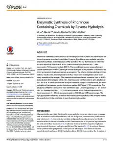
Behavioral
...
Controller Graph Model
Synthesis
} HardwareC Code
Hardware Component
Hardware Graph Model circle()
Interface Circuitry
Software Implementation using Case Descriptions In this approach, we merge different routines and describe all operations in a single routine using a method of description by cases [12]. This scheme is simpler than the coroutine scheme presented
Software Component line()
Software Implementation as Coroutines Coroutines provide an attractive means of achieving concurrency between various program threads by reducing the cost of switching execution from one thread to another [9]. In this scheme, the reprogrammable component runs a task scheduler based on a priority assigned to various routines which are maintained in a co-operative, rather than hierarchical, relationship to each other. Each coroutine maintains a local state and willingly relinquishes control of the execution machine at points of synchronization. Coroutines provide a limited form of message passing via following two primitive operations: resume and detach. A coroutine switch consists in saving the current machine status and restoring the machine status of the next process to be executed. In the most general case, where any interruptions or exceptions may cause a context switch, all machine registers and flags should be saved. In case of an R/M processor, that is a processor that provides instructions with a register and memory operands such as 8086, the code for a coroutine based scheduler amounts to 34 instructions taking about 100 bytes. The coroutine switch takes 364 cycles when implemented for 8086 processor. By contrast, implementation of a global task scheduler using subroutines takes 728 clock cycles for the 8086 processor [10]. It is possible to reduce the overhead due to context switch if all the coroutine switches are explicit and known at the compile time. By making sure that during code optimization, variable lifetimes do not cross the coroutine boundaries, then the only register that needs to be saved is the program counter of the current coroutine and also only register that should be restored is the program counter of the next coroutine to be executed. The code for a such a scheduler on 8086 processor takes 103 cycles for each context switch. By comparison, on an load/store (L/S) machine, such as DLX [11], the code for task scheduler is reduced to 17 instructions (19 machine cycles), as opposed to the general case when all 64 registers would have to be saved requiring 192 instructions.
Partitioning and Program threads generation
Thread1
Thread2
Figure 3: System Synthesis Example In order to illustrate our system synthesis approach we consider synthesis of a graphics controller that provides for drawing of lines and circles given the end coordinates (and radius in case of a circle). Figure 3 illustrates some of the steps in synthesis of the graphics controller. The HardwareC description consisting of 457 lines of code is input to the behavioral synthesis phase. The resulting system graph model is input to Vulcan-II. As a result of system partitioning and program threads generation in Vulcan-II, the system design at this stage consists of interacting hardware modules modeled by the hardware graph models and a software component modeled by program threads. Next step is to synthesize the interface circuitry that would facilitate synchronization and communication between heterogeneous system components. Synthesis of interface circuitry is driven by the requirements imposed by system synchronization. We shall revisit this example in Section 4 to show how multiple program threads are synchronized with the concurrently operating hardware portions.
3
System Synchronization
A system design consists of various components which carry out operations in response to input data. An event refers to the execution of a data input/output operation. Synchronization in a system design refers to constraints on system design that ensure the partial ordering of events and operation executions imposed by the system model must be observed in any execution trace of the system model. Some synchronization constraints are needed to ensure correctness of the execution model, for example, all the data generated within the system model must be consumed in the time order in which it was generated. Typically this is guaranteed by appropriate choice of the execution semantics for the system model. Additional constraints may be needed to ensure correctness of a set of concurrently executing models. Further, some synchronization conditions may be externally imposed. For
example, a certain precedence or simultaneity condition between execution of two operations imposed by the system control flow.
Communication Model In the system graph model, communication between two operations is indicated by presence of an edge between respective operation vertices. When considering hardware synthesis, an edge between two operations may translate into either a physical wire connection, or it may be buffered and/or blocked to facilitate asynchronous communication. Final selection of data-transfer mechanism is made based on the data transfer requirement and how individual communicating models are implemented. However, note that in a mixed system implementation, due to inherently different rates of computation between hardware and software modules, it is necessary to allow multiple executions of individual models in order to achieve high system throughput. However, in presence of variation in rates of communication across different models appropriate buffering and handshake mechanisms may be required.
3.1 Software Synchronization Our model of software component relies on the sequential execution of different threads of execution. Due to this serialization of the input system model, software synchronization is needed to ensure correct ordering of operations within the program threads and between different threads. A thread of execution already maintains an order of execution of its instructions, so a schedule of the operations is implicit to the sequential execution model of the instructions in a reprogrammable component. This solves the problem when a single thread of execution can be found for an entire description or among operations implemented in software belonging to the same thread - synchronization is only needed in points of synchronization and where the control is transferred between software and hardware. When data-dependent loops, and asynchronous message passing are present in the code, it may not always be possible to find a static schedule of the operations. If the order of execution can still be found, a single thread of execution could be determined that preserves the order in which the operations are executed. In case no such thread of execution can be determined, multiple threads of execution are required. In presence of multiple threads of executions (whether implemented as multiple programs or a single program using case descriptions described before) software synchronization consists of a mechanism to transfer control from one thread to another. In case of small number of threads, such a transfer can be done based on a statically defined priority of threads. For example, in case of two threads, control would simply switch from one thread to the other. In the general case, however, due to unbounded delay operations, we look for a dynamic scheduling of different threads of execution. Such a scheduling is done based on availability of data. Suppose we were to time stamp each data generated and also for each data request. Then the next thread of execution to be scheduled would be the one with the smallest request time stamp. Further, in order to maintain the correct order of data production and consumption, at any time the data being consumed is the one with the smallest time stamp. Such an scheme is implemented using a control FIFO that contains pointer to the next thread to be scheduled for execution [7]. Data transfer between two threads of execution can be implemented with shared memory or message passing. Shared memory can be facilitated by maintaining read and write pointers on each data-transfer. Such an scheme would add the overhead of maintaining and updating the read and write pointer for each data transfer across the program threads. Non-register based data-transfers (or data transfers which could culminate in control transfer) are well suited to be implemented as a queue connected with the control FIFO. On the other hand, register based transfers have the characteristic that once something
is written, the data may be read many times. It is possible to use processor registers to transfer information between threads. However, such a scheme requires global register assignments which are not available for reassignment by the compiler. A limited form of message passing can be achieved by using co-routine model of implementation described before.
3.2 Hardware-Software Synchronization Synchronization between hardware and software components is determined by the data transfer requirements between the sender and the receiver. A data transfer between two models can be either blocking or non-blocking. A blocking transfer protocol requires the sender(receiver) to block transfer until the corresponding receiver(sender) is ready to receive(send) data. Blocking can also be made conditional so as to reduce the associated timing penalties due to blocking [13]. With respect to their overheads, a nonblocking transfer consumes the system bus bandwidth, whereas a blocking transfer costs not only system bus bandwidth but also additional control lines that are needed to implement the required handshake. Therefore, for lower system costs, it is necessary to implement blocking only when absolutely necessary. A blocking transfer protocol can be thought of as a non-blocking transfer with an infinitely deep queue buffer. The queue size may be bounded by addition of handshake signals that treat queue as the sender or receiver of data. Alternatively, in presence of specific constraints on rates of data transfer, the queues can be sized algorithmically [14]. For a given data-transfer edge in the system graph model, we first attempt to determine the rates of data production and consumption associated with the sender and receiver models. Such a rate determination requires specification of data rates for external inputs and outputs. In case of unknown or varying data rates, a blocking protocol for both sending and receiving ends is selected. Either sender or receiver end of a transfer can be made non-blocking if it can be determined that the corresponding operations are always slower. In case of perfectly matched data-rates a synchronous non-blocking protocol is selected. After selecting transfer protocols for different data-transfers across the hardware and software models, the interface circuitry can be synthesized using asynchronous and synchronous logic synthesis techniques [15] [16]. For a description of the interface architecture the reader is referred to [7]. System Graph Model
Ariadne SLIF Netlist (Gate-level Description)
DLX Assembly Code
DLX Simulator
POSEIDON
Mercury
Implements: a. Interface protocol between models b. event-driven simulation of multiple models c multiple clocks and clock rates between models
Figure 4: Event-driven simulation of a mixed system design
4
Simulation of Hardware-Software Systems
We have developed an event-driven simulator, named Poseidon, that performs concurrent simulation of multiple functional models
InRq
ASIC Hardware
PROCESSOR
comm outPort
Consumer
Producer OutAk
inChannel
Figure 5: Simulation Example 1
Line
line data queue
Circle
circle data queue
Scheduler
Coordinate Generator
FIFO Control Control FIFO
Software Component: main program
implemented either as a program or as application-specific hardware. The software component is compiled into the assembly code of the target microprocessor. Poseidon currently supports simulation of assembly code for the DLX microprocessor, a RISC oriented load/store processor [11]. The hardware component of system design can be simulated either before or after the structural synthesis phase. The graph model before structural synthesis is simulated using program Ariadne. A gate-level description of the hardware component of system design is generated using structural synthesis techniques in program Hebe and simulated using program Mercury. Thus, Poseidon supports simulation of partially synthesized hardware modules along with the software component of the system design. Poseidon maintains an event queue which stores all simulation models sorted by their activation times. After simulating an event, the event is enqueued in the event queue. A system specification in Poseidon consists of following parts: 1. Model declarations: consists of declarations of the concurrently executing simulation models. Models can be either software or hardware models. Each model has an associated clock signal and clock cycle-time used for its simulation. It is assumed that the clock cycle-times are a rational multiple of each other. Further it is assumed that different models supply (latch) data at the interface using flip-flops at the interface edge-triggered by their respective clock signals. 2. Model interconnections: The interface between different system components is specified by connections among models. A connection between two models may be either a direct connection through a wire, or a port connection through a register or a queue. Queues can have multiple fanins and fanouts. Signal assignments indicate direct connections between respective models. For connections such as queues that require existence of additional control signals for synchronization, it is possible to group signals having identical synchronization requirements together for a given set of synchronization signals. 3. Communication protocols: Interface protocol for datatransfer is specified via guarded commands [17]. A guarded command is executed only when some precondition is true. Each precondition is specified as a logic equation of signal values and transitions. There are four commands recognized by the connection types. Enqueue and dequeue are used for queues port connections and load and store are used for register port connections. 4. System outputs: Outputs to be observed during simulation runs may be indicated by direct connections to the internal signals in the system model. For illustration purposes, we consider a simple example of two models, Producer and Consumer connected by means of a finitely sized queue as shown in Figure 5. We consider two cases: one in which the producer model is implemented in software and consumer in hardware and the other in which producer, consumer implementations are reversed. Example 1 shows system specification for this example for the first case. The three first lines of the specification declare the models to be simulated. Model io models the external system inputs and outputs. The following parameter specifies the clock period of the clock signal associated with the respective model. A value of 3.0 for the consumer model
int lastPC[MAXCRS]={scheduler,circle,line,main); int current=MAIN; int *controlFIFO = (int *) 0xaa0000; int *controlFIFO_rq = (int *) 0xaa0004; main(){ resume(SCHEDULER); }; int nextCoroutine; scheduler(){ resume(LINE); resume(CIRCLE); while (!RESET){ do { nextCoroutine = *controlFIFO; } while ((nextCoroutine & 0x4) != 0x4); resume(nextCoroutine & 0x3); } }
Figure 6: Example 2: Graphics Controller Design indicates that consumer is implemented in an ASIC technology that uses a clock signal that is three times slower than the clock used by the reprogrammable component, which is usually a custom designed component. The system input/outputs are sampled here at the same rate as the consumer. The last two parameters specify the directory location where the model description can be found and the model name. The queue statement declares a queue named, comm, which is 4 bits wide and 3 words deep. We use rq and ak signals to implement a blocking communication protocol as indicated by the guarded commands. A ‘+’ suffix indicates rising edge transition of the corresponding signal. A ‘-’ suffix indicates falling edge transition. Symbols ‘&’ and ‘!’ indicate the boolean and and not operations. Example 1:
Specification of a producer-consumer pair
(Figure 5). # Models model IO io 1.0 /local/ioDir IO; model P dlx 1.0 /local/ProducerDir Producer; model C mercury 3.0 /local/ConsumerDir Consumer; # Connections queue [4] comm[3]; C.RESET = IO.RESET; C.r[0:0] = IO.r[0:0]; # Communication protocol P.0xff004[0:0] = !comm.full; C.b_rq = !comm.empty; when (P.0xff000_wr+ & ! comm.full) do comm[0:3] enqueue P.0xff000[0:3]; when (C.b_ak+ & ! comm.empty) do comm[0:3] dequeue C.b[0:3]; # Outputs IO.inChannel[0:3] = P.0xff000[0:3]; IO.outPort[0:3] = C.c[0:3]; IO.InRq = P.0xff000_wr; IO.OutAk = C.b_ak;
In order to illustrate the effect of software and hardwaresoftware synchronization mechanisms we now consider the design of the graphics controller introduced in Figure 3. Figure 6 shows the final implementation of the system design. The design consists of application-specific portions containing initial coordinate generators and control logic for controlFIFO and a software portion implemented on the DLX processor. The software component consists two threads of execution corresponding to the line and circle drawing routines. Both program threads generate coordinates that are used by the dedicated hardware. Input to Poseidon consists of gate-level description of the ASIC hardware, assembly code of the coroutines, and a description of the interface. Example 2 shows the Poseidon interface specification of the graphics controller design.
5
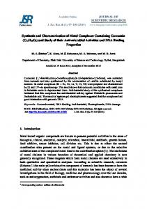
Figure 7: Example 2: Simulation of Graphics Controller
Example 2:
Specification of the graphics controller
interface (Figure 6). model model model model model
gc io 1.0 DIR GraphicsController; ccoord mercury 5.0 DIR gcircle; lcoord mercury 5.0 DIR gline; mp dlx 1.0 DIR main; CF mercury 1.0 DIR control;
queue [1] lqueue[16], cqueue[16]; queue [3] controlFifo[2]; CF.r[0:0] = lcoord.run[0:0] = ccoord.run[0:0] = gc.run[0:0]; CF.RESET = lcoord.RESET = ccoord.RESET = gc.RESET; CF.lrq[0:0] = !lqueue.empty; CF.lak[0:0] = mp.0xff004_rd; CF.crq[0:0] = !cqueue.empty; CF.cak[0:0] = mp.0xee004_rd; mp.0xee004[0:0] = !cqueue.empty; mp.0xff004[0:0] = !lqueue.empty; # Lqueue when (lcoord.queue_rq+ & !lqueue.full) do lqueue[15:0] enqueue lcoord.queue[15:0]; lcoord.queue_ak = !lqueue.full; when (mp.0xff000_rd+ & !lqueue.empty) do lqueue[15:0] dequeue mp.0xff000[15:0]; mp.0xff000[16:16] = !lqueue.empty; ...
Conclusions
Synthesis using application-specific as well as reprogrammable components provides a promising extension of high-level synthesis approaches to realize complex system designs without corresponding increase in the magnitude of the synthesis tasks. Use of a reprogrammable component, however, poses interesting problems due to inherently serial nature of program execution that must interact with concurrently operating hardware portions. Thus synchronization between various components constitutes one of the most important issues in system synthesis. We have presented an approach to synthesis of systems containing both application-specific and reprogrammable components and synchronization schemes that are used to facilitate data-transfer across concurrently executing system models. The resulting hardware and software components are simulated using an event-driven simulator, Poseidon which provides cycle-by-cycle simulation results. Since the selection of a synchronization scheme is driven by requirements of data-transfer rates, automatic selection of interface protocol can be made based on the data-rate constraints imposed on the system model. Work is underway to develop an automated tool to generate Poseidon interface specification and to synthesize appropriate interface circuitry once such a selection is made of all data transfers.
6
Acknowledgments
This research was sponsored by NSF-ARPA, under grant No. MIP 8719546 and, by DEC jointly with NSF, under a PYI Award program, and by a fellowship provided by Philips/Signetics. We acknowledge also support from ARPA, under contract No. J-FBI-89101. The second author was partially supported by CNPq-Brazil under contract 200212/90.7.
References
[1] G. D. Micheli, D. C. Ku, F. Mailhot, and T. Truong, “The Olympus Synthesis System for Digital Design,” IEEE Design and Test Magazine, pp. 37–53, Oct. 1990. # ControlFifo when (CF.outline_rq+ & !controlFifo.full) do controlFifo[1:0] enqueue [2] J. Rabaey, H. D. Man, and et. al., “Cathedral II: A Synthesis System for Multiprocessor DSP outline[1:0]; Systems”, in Silicon Compilation, editor: D. Gajski , pp. 311–360. Addison Wesley, 1988. CF.outline_ak = !controlFifo.full; ... [3] D. Thomas, E. Lagnese, R. Walker, J. Nestor, J. Rajan, and R. Blackburn, Algorithmic and Register-Transfer Level: The System Architect’s Workbench. Kluwer Academic Publishers, # Output specification 1990. gc.x_out[7:0] = mp.0xff100[7:0]; gc.y_out[7:0] = mp.0xff104[7:0]; [4] R. Camposano and W. Rosenstiel, “Synthesizing Circuits from Behavioral Descriptions,” gc.controlFifo[1:0] = controlFifo[1:0]; IEEE Transactions on CAD/ICAS, vol. 8, no. 2, pp. 171–180, Feb. 1989. gc.CF_ready = !controlFifo.empty; ... [5] M. B. Srivastava and R. W. Broderson, “Rapid-Prototyping of Hardware and Software in a Unified Framework,” in Proceedings of the International Conference on Computer-Aided Design, (Santa Clara), pp. 152–155, 1991.
Figure 7 shows some results of Poseidon simulations of the graphics controller. The hardware-software synchronization specified in Example 2 follows the scheme described in Section 3.2. The data-driven dynamic scheduling of program threads is achieved through the use of a 3-deep controlFIFO. In Figure 7, the circle and line drawing program threads are identified by id numbers 1 and 2 respectively. The program threads are implemented using the coroutine scheme described in Section 2. Signal ol rq and oc rq in Figure 7 indicate when the line and circle thread id’s are being enqueued on data request from the software component. Variable time distance between oc rq requests is due to data-dependent delay offered by the circle drawing routine in software. controlFifo wr represents when a thread of execution enqueues its thread id in the control FIFO and then yields the execution to another thread. x out and y out are the coordinates generated by the line routine and xcircle and ycircle are the coordinates generated by the circle routine. CF ready signals when the control FIFO is not empty and controlFifo rd shows when the scheduler checks to see if the control FIFO is not empty (and eventually read it).
[6] D. C. Ku and G. D. Micheli, “Synthesis of ASICs with Hercules and Hebe”, in High-level VLSI Synthesis, editors: Raul Camposano, Wayne Wolf, pp. 177–203. Kluwer Academic Publishers, 1991. [7] R. K. Gupta and G. D. Micheli, “System-level Synthesis Using Re-programmable Components,” in Proceedings of the European Design Automation Conference, Mar. 1992. [8] G. R. Andrews and F. Schneider, “Concepts and Notations for Concurrent Programming,” ACM Computing Surveys, vol. 15, no. 1, pp. 3–44, Mar. 1983. [9] M. E. Conway, “Design of a Separate Transition-Diagram Compiler,” Comm. of the ACM, vol. 6, pp. 396–408, 1963. [10] R. K. Gupta and G. D. Micheli, “System Synthesis via Hardware-Software Co-design,” CSL Technical Report CSL-TR, Stanford University, 1992. [11] J. L. Hennessey and D. A. Patterson, Computer Architecture: A Quantitative Approach, ch. 3. Morgan-Kaufmann, 1990. [12] P. J. H. King, “Decision Tables,” The Computer Journal, vol. 10, no. 2, Aug. 1967. [13] I. C. Wand and A. J. Wellings, Distributed Computing, F. B. Chambers et. al. editors, ch. 14: Programming Languages, pp. 201–215. Academic Press, 1984. [14] T. Amon and G. Borriello, “Sizing Synchronization Queues: A Case Study in Higher Level Synthesis,” in Proceedings of the 28th Design Automation Conference, June 1991. [15] T. H. Meng, Synchronization Design for Digital Systems, ch. Synthesis of Self-Timed Circuits, pp. 23–63. Kluwer Academic Publishers, 1991. [16] G. Borriello and R. Katz, “Synthesis and Optimization of Interface Transducer Logic,” in Proceedings of the IEEE Transactions on CAD/ICAS, Nov. 1987. [17] E. W. Dijkstra, “Guarded Commands, Nondeterminacy, and Formal Derivation of Programs,” CACM, vol. 18, no. 8, pp. 453–457, Aug. 1975.