Jun 1, 2004 - (73) Assignee: Immersion Corporation, San Jose, CA. (Us). ( * ) Notice: Subject to any disclaimer, the term of this patent is extended or adjusted under 35 ...... picture (jog) control. When the ... mid-point of its range of motion.
US007567243B2
(12) United States Patent
(10) Patent N0.: (45) Date of Patent:
Hayward (54)
SYSTEM AND METHOD FOR LOW POWER
4,050,265 A
HAPTIC FEEDBACK
4,131,033 A 4,236,325 4,262,240 4,513,235 4,553,080 4,560,983
(73) Assignee: Immersion Corporation, San Jose, CA
(Us) (*)
Notice:
A A A A A
9/1977 Drennen et al.
7/1979 Salsbury 12/1980 4/1981 4/1985 11/1985 12/1985
Hall et al. Arai Acklam et al. Cannon et al. Williams
Subject to any disclaimer, the term of this patent is extended or adjusted under 35
U.S.C. 154(b) by 752 days.
(Continued)
(21) App1.No.: 10/858,216 (22) Filed:
FOREIGN PATENT DOCUMENTS DE
Jun. 1, 2004
(65)
3524439
1/1987
Prior Publication Data US 2005/0012710A1
(Continued)
Jan. 20, 2005
OTHER PUBLICATIONS
Related US. Application Data
(60) Provisional application No. 60/474,434, ?led on May 30, 2003. (51)
Jul. 28, 2009
12/1978 Wright et al.
4,160,508 A
(75) Inventor: Vincent Hayward, Montreal (CA)
US 7,567,243 B2
The PowerBraille, Refreshable Braille Display User’s Guide; BlaiZie Engineering; 1998.
(Continued)
Int. Cl. G09G 5/00 G06F 3/01
Primary ExamineriHenry N Tran
(2006.01) (2006.01)
(74) Attorney, Agent, orFirmiwomble Carlyle Sandridge &
(52)
US. Cl. ..................... .. 345/184; 345/156; 715/701;
(58)
Field of Classi?cation Search ............... .. 345/156,
Rice, PLLLC
715/702
(57)
ABSTRACT
345/157,161,163,167,168,184; 715/700, 715/701, 702; 200/175, 11 TW, 6 B, 6 BB, 200/6 C, 19.2; 463/37, 38, 30; 700/17, 19,
Systems and methods for loW poWer consumption haptic feedback are described. In one described system, a device
700/83*85
comprises a manipulandum and a haptic effect generator in communication With the manipulandum. The actuator is operable to provide a ?rst haptic pro?le associated With a ?rst mechanical con?guration and a second haptic pro?le associ ated With a second mechanical con?guration. The device also comprises an actuator in communication With the haptic effect generator, Which is operable to sWitch the haptic effect
See application ?le for complete search history. (56)
References Cited U.S. PATENT DOCUMENTS 3,157,853 3,220,121 3,497,668 3,517,446
A A A A
11/1964 11/1965 2/1970 6/1970
Hirsch Cutler Hirsch Corlyon et al.
3,902,687 A
9/1975 Hightower
3,903,614 A
9/1975 Diamond et al.
generator between the ?rst haptic pro?le and the second hap tic pro?le. 27 Claims, 7 Drawing Sheets
104a 104b 104C 104d
|
\106
110
1
\ H
B
108 112
\\
\1
116a 11Gb 116C 116d
US 7,567,243 B2 Page 2 6,271,834 B1 6,283,859 B1 6,307,285 B1
US. PATENT DOCUMENTS
4,581,491 4,599,070 4,652,805 4,706,294 4,708,656 4,713,007 4,758,165 4,794,388 4,859,922 4,868,549 4,891,764 4,930,770 4,934,694 4,943,866 4,947,097 5,019,761 5,022,407 5,035,242 5,038,089 5,078,152 5,185,561 5,186,695 5,187,630 5,189,355 5,191,320 5,204,600 5,212,473 5,220,260 5,227,594 5,240,417 5,254,919 5,261,291 5,270,689 5,271,290 5,275,174 5,299,810 5,309,140 5,334,027 5,381,080 5,382,373 5,396,266 5,414,337 5,466,213 5,542,672 5,547,382 5,559,432 5,578,238 5,627,531 5,665,946 5,683,615 5,691,898 5,705,085 5,730,655 5,766,016 5,767,839 5,781,172 5,785,630 5,825,308 5,889,670 5,914,705 5,944,151 6,002,184 6,008,800 6,020,875 6,087,829 6,100,476 6,111,577 6,147,422 6,154,201 6,219,034 6,262,717
4/1986 7/1986 3/1987 11/1987 11/1987 12/1987 7/1988 12/1988 8/1989 9/1989 1/1990 6/1990 6/1990 7/1990 8/1990 5/1991 6/1991 7/1991 8/1991 1/1992 2/1993 2/1993 2/1993 2/1993 3/1993 4/1993 5/1993 6/1993 7/1993 8/1993 10/1993 11/1993 12/1993 12/1993 1/1994 4/1994 5/1994 8/1994 1/1995 1/1995 3/1995 5/1995 11/1995 8/1996 8/1996 9/1996 11/1996 5/1997 9/1997 11/1997 11/1997 1/1998 3/1998 6/1998 6/1998 7/1998 7/1998 10/1998 3/1999 6/1999 8/1999 12/1999 12/1999 2/2000 7/2000 8/2000 8/2000 11/2000 A *
Boothroyd
8/2001 May et al. 9/2001 Carlson et al. 10/2001 Delson et al.
Hladky et al.
6,320,487 B1*
11/2001
Kohn Ouchida De Vries et al. Alban Tieman et al. Matthews TauchenitZ et al. Af?nito et al. McIntosh Baker McIntosh Barker et al. Tao Kraft Horch et al. Franklin
6,324,928 B1
12/2001 Hughes
6,337,678 B1
1/2002 Fish
6,348,772 B1 6,373,465 B2
2/2002 May 4/2002 Jolly et al.
6,394,239 B1
5/2002 Carlson
6,420,806 B2
7/2002 Wittig
6,422,941 6,437,771 6,468,158 6,480,752
7/2002 Thorner et al.
B1
B1 B1 B1
7/2003
6,589,117 B1 6,591,175 B2
7/2003 Moritome et al. 7/2003 Numata et al.
RE38,242 E
9/2003 Engel et al.
6,636,197 6,636,202 6,637,311 6,640,940 6,646,632 6,876,891 6,965,370
SZakaly Mangseth et al. MacKay et al. Larkins et al.
MacKay
B1 B2 B2 B2 B2 B1 B2
6,987,508 B2 *
Kahkoska Louis Schuler Russo Smithson et al.
2001/0052893 2002/0044132 2002/0067336 2002/0084983 2002/0158842 2003/0006958 2003/0038774 2003/0079948 2003/ 0080939
Bridges et al. Schoch et a1. Hermann Fischer Cook Pierce Everett Wherlock Schnell et al. Carlson et al. Brirnhall Schuler
8/2002 Rosenberg et al. 10/2002 Ootori et al. 11/2002 Blume et al.
6,587,091 B2 *
6,613,997 B2 *
Bond Good et al.
Miller et al. .............. .. 335/274
A1 A1 A1 A1 A1 A1 A1 A1 A1
2003/0128192 A1
2003/0184518 A1
9/2003
10/2003 10/2003 10/2003 11/2003 11/2003 4/2005 11/2005 1/2006
12/2001 4/2002 6/2002 7/2002 10/2002 1/2003 2/2003 5/2003 5/2003
Serpa ....................... .. 345/156
Oster et al.
............... .. 200/564
Goldenberg et al. Ishmael, Jr. et al. Barden Carlson Wegmuller et al. Schuler et al. Gregorio et al. Numata et al. ............ .. 345/184
Jolly et al. Fish Wegmuller et al.
Boldy Guy et al. Onodera Piot et al. Jolly et al. Kobayashi
7/2003 van Os
10/2003 Numata et al.
FOREIGN PATENT DOCUMENTS EP EP EP EP JP JP JP JP
Hogan Meredith Yamasaki
Logue Weiss et al. Posso et al.
0349086 0626634 0 789 321 A2 1 217 496 A2 01-003664 02-109714 04-007371 05-193862
1/1990 11/1994 8/1997 6/2002 7/1990 1/1992 8/1993 1/1995
OTHER PUBLICATIONS
Nishijima et al. Munoz
Rosenberg et al.
Kim Nice; How Washing Machines Work; http://home. howstuffworks.com/washer.htm/printable; Aug. 20, 2003; pp. 12-16.
MunoZ et al.
Allen Bernard; Company Sees MEMS As Solution For A?ordable
Meredith Sinclair
Braille Displays; Smalltimes, News about MEMS, Nanotechnology
Rosenberg
cfm?dociid:3432; Apr. 9, 2002; pp. 1-3.
Engel et al.
Annex to Form PCT/ISN206, Communication Relating To the Results of the Partial International Search Report; Sep. 11, 2005; 2
and
Bobick et al.
Rosenberg
http://www.smalltimes.com/printidoc.
PgS~
Schuler et al. Johnson et al.
Microsystems;
International Search Report; Jan. 17, 2006; 4 pgs. ........... .. 345/163
Jakobs et al. Delson et al.
Pryor
Rosenberg, Louis B., “Virtual Fixtures”: Perceptual Overlays Enhance Operator Performance in Telepresence Tasks, Dept. of Mechanical Engineering, Stanford University, Aug. 1994, pp. ii-214. Snibbe, Scott S., “Haptic Techniques for Media Control,” In Proceed
Moore et al.
ing of the 14th Annual ACM Symposium on User Interface Software
Jager
and Technology, 2001, pp. 1-10. Adelstein, “A Virtual Environment For The Study of Human Arm
AdamietZ et al. Zilles et al. Delson et al.
11/2000 Levin et al. ............... .. 345/184
4/2001 Elbing et al. 7/2001 Donohue et al.
Tremor,” Ph.D. Dissertation, Dept. of Mechanical Engineering, MIT, Jun. 1989.
Adelstein, “Design and Implementation of a Force Re?ecting Manipulandum for Manual Control research,” DSC-vol. 42, Advances in Robotics, Edited by H. KaZerooni, pp. 1-12, 1992.
US 7,567,243 B2 Page 3 Aukstakalnis et al., “Silicon Mirage: The Art and Science of Virtual
KacZmarek et al., “Tactile Displays,” Virtual Environment Technolo
Reality,” ISBN 0-938151-82-7, pp. 129-180, 1992. Baigrie, “Electric Control LoadingiA Low Cost, High Performance Alternative,” Proceedings, pp. 247-254, Nov. 6-8, 1990. BejcZy et al., “Kinesthetic Coupling Between Operator and Remote
gies.
Kontarinis et al., “Display of High-Frequency Tactile Information to
Teleoperators,” Telemanipulator Technology and Space Telerobot ics, Won S. Kim, Editor, Proc. SPIE vol. 2057, pp. 40-50, Sep. 7-9,
Manipulator,” International Computer Technology Conference, The
1993.
American Society of Mechanical Engineers, San Francisco, CA,
Marcus, “Touch Feedback in Surgery,” Proceedings of Virtual Real
Aug. 12-15,1980.
ity and Medicine The Cutting Edge, Sep. 8-11, 1994. McAffee, “Teleoperator Subsystem/Telerobot Demonstrator: Force Re?ecting Hand Controller Equipment Manual,” JPL D-5172, pp. 1-50, A1-A36, B1-B5, C1-C36, Jan. 1988.
BejcZy, “Sensors, Controls, and Man-Machine Interface for Advanced Teleoperation,” Science, vol. 208, No. 4450, pp. 1327 1335, 1980. BejcZy, “Generalization of Bilateral Force-Re?ecting Control of
Manipulators,” Proceedings Of Fourth CISM-IFToMM, Sep. 8-12, 1981.
BejcZy, et al., “Universal Computer Control System (UCCS) For Space Telerobots,” CH2413-3/87/0000/0318501.00 1987 IEEE, 1987.
BejcZy et al., “A Laboratory Breadboard System for Dual-Arm Teleoperation,” SOAR ’89 Workshop, J SC, Houston, TX, Jul. 25-27, 1989.
Brooks et al., “Hand Controllers for TeleoperationiA State-of-the
Art Technology Survey and Evaluation,” JPL Publication 85-11; NASA-CR-175890; N85-28559, pp. 1-84, Mar. 1, 1985. Burdea et al., “Distributed Virtual Force Feedback, Lecture Notes for Workshop on Force Display in Virtual Environments and its Appli cation to Robotic Teleoperation,” 1993 IEEE International Confer ence on Robotics and Automation, pp. 25-44, May 2, 1993. Caldwell et al., “Enhanced Tactile Feedback (Tele-Taction) Using a
Multi-Functional Sensory System,” 1050-4729/93, pp. 955-960, 1993.
“Cyberman Technical Speci?cation,” Logitech Cyberman SWIFT Supplement, Apr. 5, 1994. Eberhardt et al., “OMARiA Haptic Display for speech perception
Minsky, “Computational Haptics: The Sandpaper System for Syn thesiZing Texture for a Force-Feedback Display,” Ph.D. Dissertation, MIT, Jun. 1995. Ouh-Young, “Force Display in Molecular Docking,” Order No. 9034744, p. 1-369, 1990. Ouh-Young, “A Low-Co st Force Feedback Joystick and Its Use in PC Video Games,” IEEE Transactions on Consumer Electronics, vol. 41, No. 3, Aug. 1995. Ouhyoung et al., “The Development of a Low-Cost Force Feedback Joystick and Its Use in the Virtual Reality Environment,” Proceedings of the Third Paci?c Conference on Computer Graphics and Applica
tions, Paci?c Graphics ’95, Seoul, Korea, Aug. 21-24, 1995. Patrick et al., “Design and Testing of A Non-reactive, Fingertip, Tactile Display for Interaction with Remote Environments,” Coop erative Intelligent Robotics in Space, Rui J. deFigueiredo et al., Editor, Proc. SPIE vol. 1387, pp. 215-222, 1990. Pimental et al., “Virtual Reality: through the new looking glass,” 2'” Edition; McGraw-Hill, ISBN 0-07-050167-X, pp. 41-202, 1994. RabinowitZ et al., “Multidimensional tactile displays: Identi?cation of vibratory intensity, frequency, and contactor area,” Journal of The Acoustical Society ofAmerica, vol. 82, No. 4, Oct. 1987. Russo, “The Design and Implementation of a Three Degree of Free
dom Force Output Joystick,” MIT Libraries Archives Aug. 14, 1990,
by deaf and deaf-blind individuals,” IEEE Virtual Reality Annual International Symposium, Seattle, WA, Sep. 18-22, 1993. Eberhardt et al., “Including Dynamic Haptic Perception by The Hand: System Description and Some Results,” DSC-vol. 55-1, Dynamic Systems and Control: vol. 1, ASME 1994.
pp. 1-131, May 1990. Russo, “Controlling Dissipative Magnetic Particle Brakes in Force Re?ective Devices,” DSC-vol. 42, Advances in Robotics, pp. 63-70,
Gobel et al., “Tactile Feedback Applied to Computer Mice,” Interna tional Journal of Human-Computer Interaction, vol. 7, No. 1, pp. 1-24, 1995. Gotow et al., “Controlled Impedance Test Apparatus for Studying Human Interpretation of Kinesthetic Feedback,” WA11-11:00, pp.
tion, vol. 9, No. 11, Nov. 1994. Shimoga, “Finger Force and Touch Feedback Issues in Dexterous Telemanipulation,” Proceedings of Fourth Annual Conference on
332-337.
technic Institute, Sep. 30-Oct. 1, 1992.
Howe, “A Force-Re?ecting Teleoperated Hand System for the Study of Tactile Sensing in Precision Manipulation,” Proceedings of the
Snow et al., “Model-X Force-Re?ecting-Hand-Controller,” NT Con trol No. MPO-17851; JPL Case No. 5348, pp. 1-4, Jun. 15, 1989.
1992 IEEE International Conference on Robotics and Automation,
Stanley et al., “Computer Simulation of Interacting Dynamic Mechanical Systems Using Distributed Memory Parallel Proces sors,” DSC-vol. 42, Advances in Robotics, pp. 55-61, ASME 1992. Tadros, “Control System Design for a Three Degree of Freedom Virtual Environment Simulator Using Motor/Brake Pair Actuators”,
Nice, France, May 1992. IBM Technical Disclosure Bulletin, “Mouse Ball-Actuating Device With Force and Tactile Feedback,” vol. 32, No. 9B, Feb. 1990.
Iwata, “Pen-based Haptic Virtual Environment,” 0-7803-1363-1/93 IEEE, pp. 287-292, 1993. Jacobsen et al., “High Performance, Dextrous Telerobotic Manipu lator With Force Re?ection,” Intervention/ROV ’91 Conference &
Exposition, Hollywood, Florida, May 21-23, 1991. Jones et al., “A perceptual analysis of stiffness,” ISSN 0014-4819
ASME 1992.
Scannell, “Taking a Joystick Ride,” Computer Currents, Boston Edi
Intelligent Robotic Systems for Space Exploration, Rensselaer Poly
MIT Archive © Massachussetts Institute of Technology, pp. 1-88, Feb. 1990.
Terry et al., “Tactile Feedback In A Computer Mouse,” Proceedings of Fourteenth Annual Northeast Bioengineering Conference, Univer sity ofNew Hampshire, Mar. 10-11, 1988.
Springer International (Springer-Verlag); Experimental Brain Research, vol. 79, No. 1, pp. 150-156, 1990.
* cited by examiner
US. Patent
Jul. 28, 2009
Sheet 1 of7
US 7,567,243 B2
3-,
3n“B6:u2.,
2,N:2;Q:
32.25_.
.QE3.
US. Patent
Jul. 28, 2009
Sheet 2 of7
US 7,567,243 B2
1043 104b 1946 104d __
f
_
.
104 n/
\
120
__\—‘____L___J \ r1
\106
110
FIG. 15
108 112
119
US. Patent
Jul. 28, 2009
210 208
202
204
I214
Sheet 3 of7
212
US 7,567,243 B2
US. Patent
Jul. 28, 2009
Sheet 4 of7
US 7,567,243 B2
E6Eamon
2682%
a
a
Sc2E85 MOSign
.5 m
6wobadm Elm
56@32AE:
US. Patent
Jul. 28, 2009
Sheet 5 of7
US 7,567,243 B2
602
608
612 602
Fig. 606610 61' 4
US. Patent
Jul. 28, 2009
Sheet 6 of7
kagm wI.m~/ \\\\\\\\\\\\\\\\\\\\\\\\‘ \
New
@V/ /
N;V
a;
N:
US 7,567,243 B2
US 7,567,243 B2 1
2
SYSTEM AND METHOD FOR LOW POWER HAPTIC FEEDBACK
FIG. 1C is a sectional vieW shoWing a second channel
having surface features including depressions and a stop, con?gured to provided a second haptic pro?le; FIG. 1D is a sectional vieW shoWing a channel con?gured
CROSS-REFERENCE TO RELATED APPLICATIONS
to provided a further haptic pro?le; FIG. IE is a schematic diagram illustrating a knob With
programmable detent pro?les in another embodiment of the
This patent application claims priority to US. Provisional Application Ser. No. 60/474,434, ?led May 30, 2003, the
present invention; FIG. 2 is an schematic diagram of a resistive actuator With
entirety of Which is hereby incorporated by reference.
programmable friction in one embodiment of the present
invention;
FIELD OF THE INVENTION
FIG. 3 is a ?owchart illustrating a method for controlling the resistive actuator of FIG. 2 in one embodiment of the
The present invention generally relates to haptic feedback.
present invention;
The present invention more speci?cally relates to kinesthetic loW poWer force feedback devices.
FIGS. 4 and 5 are schematic diagrams illustrating a pro grammable surface feel in one embodiment of the present
invention;
BACKGROUND
FIGS. 6 and 7 are schematic diagrams illustrating a pro
grammable surface feel in another embodiment of the present
Many conventional buttons, sliders, dials, and other con
invention; and
trols provide tactile or haptic feedback to the user. Feedback may be provided to the user by mechanical elements, such as detents, Which are fabricated into the device. The feedback
provided by devices relying primarily or solely on mechani cal elements is rarely variable and, if variable, is not control lable in real time and hence is not programmable. Some conventional controls comprise active or resistive (also referred to as passive) feedback, Which is controllable in real time, see, e.g., US. Pat. No. 5,220,260. The addition of controllable haptic feedback to a device normally requires an
FIG. 8 is a ?owchart illustrating a process for controlling the operation of an actuator, such as the actuator shoWn in FIGS. 6 and 7, in one embodiment of the present invention. 25
Embodiments of the present invention comprise systems and methods for loW poWer haptic feedback. There are a
variety of systems and methods according to the present 30
actuator, and the actuator requires a poWer source. In devices
designed for loW poWer consumption, such as cell phones and other handheld devices, the poWer necessary to supply the actuator may be di?icult to provide. Thus, a need exists for systems and methods for providing
DETAILED DESCRIPTION
invention. One device according to the present invention comprises a manipulandum, a haptic effect generator, and an actuator. The
device may be con?gured such that the haptic effect generator is in communication With the manipulandum. The manipu 35
controllable haptic feedback While minimizing poWer
landum may be a knob, a slider, a push button, a joystick, or
other manipulandum. The haptic effect generator may be operable to provide at least tWo haptic pro?lesione associ
requirements.
ated With a ?rst mechanical con?guration and another asso
SUMMARY 40
example, they may be independent, or they may be combined
Embodiments of the present invention provide systems and
in one or more ?les, data sets, records, or transmissions.
methods for loW poWer consumption haptic feedback. In one embodiment according to the present invention, a device comprises a manipulandum and a haptic effect generator in
communication With the manipulandum. The haptic effect generator is operable to provide a ?rst haptic pro?le associ
The actuator may comprise a solenoid, DC motor, shape memory alloy (SMA), or other suitable actuator. The actuator 45
able manner. For example, one haptic effect generator com
The device may also comprise an actuator in communication 50
are substantially parallel to one another. Each channel com
Further details and advantages of the present invention are set forth beloW. 55
BRIEF DESCRIPTION OF THE FIGURES
60
An actuator in communication With the folloWer is oper able to move the folloWer betWeen the channels (or the tWo
FIG. 1A is a schematic diagram illustrating a knob With programmable detent pro?les in one embodiment of the
surface features con?gured to provided a ?rst haptic pro?le;
a surface, or paths on multiple surfaces, that is not Within a channel. For example, a folloWer may be con?gured to folloW the surface of a cam.
nying draWings, Wherein:
FIG. 1B is a sectional vieW shoWing a ?rst channel having
effect generator in such an embodiment also comprises a folloWer. A folloWer is an element con?gured to folloW a surface or surface feature. IN one embodiment, the folloWer may be con?gured to folloW a channel. In another embodi
ment, the folloWer may be con?gured to folloW a path along
These and other features, aspects, and advantages of the
present invention;
prises a surface. The surface comprises tWo channels, Which
prises a plurality of surface features (e.g., depressions, pro trusions, stops, etc.), Which de?ne a haptic pro?le. The haptic
second haptic pro?le.
present invention are better understood When the folloWing Detailed Description is read With reference to the accompa
may be in communication With the haptic effect generator, and may be operable to sWitch the haptic effect generator
betWeen the ?rst haptic pro?le and the second haptic pro?le. The haptic effect generator may be con?gured in any suit
ated With a ?rst mechanical con?guration and a second haptic pro?le associated With a second mechanical con?guration.
With the haptic effect generator and operable to sWitch the haptic effect generator betWeen the ?rst haptic pro?le and the
ciated With a second mechanical con?guration. The tWo hap tic pro?les may be con?gured in any suitable manner. For
paths) and thereby change the haptic pro?le. The surface may 65
comprise more than tWo channels.
In another embodiment, the haptic effect generator com prises a ?rst surface comprising a ?rst plurality of surface
US 7,567,243 B2 3
4
features and a second surface comprising a second plurality of surface features. The tWo surfaces are substantially parallel to one another and con?gured to move together. The haptic effect generator also comprises a folloWer to folloW a surface,
The present invention is not limited to the examples given, but the examples are given to illustrate types of embodiments of the present invention.
and an actuator to move the folloWer from the ?rst surface to a second surface.
Examples With Reference to the Figures
In one embodiment, the haptic effect generator may be con?gured to comprise a cylinder having a plurality of cams,
mechanical con?gurations. The lever may comprise a spring
Referring noW to the draWings in Which like numerals indicate like elements throughout the several ?gures, FIG. 1A is a schematic diagram illustrating a knob With programmable detent pro?les in one embodiment of the present invention. Embodiments of the present invention provide systems and
loaded lever, a spring-loaded pin, a paWl, and/ or other suitable
methods for providing haptic feedback to a user that mini
and a lever operable to engage at least one of the plurality of cams. The plurality of cams may have the same or different
structure. As another example, the haptic effect generator
miZes the consumption of poWer. Haptic feedback provides
may comprise a brake. A single-part shoe brake or other
tactile sensations that depend on movement, such as move
suitable brake may be used. A screW or other structure may be used to vary a friction exerted by the brake. A DC motor or
the present invention, the poWer for providing the haptic
ment of a user’ s hand or of an actuator. In one embodiment of
other device may be used to turn or move the screW or other
effect is provided by a user moving a manipulandum. The
such structure.
user experiences multiple haptic pro?les that depend on mul
As another example, the haptic effect generator may be con?gured such that it may be operable to alter a surface of the manipulandum. A pin or other structure may be positioned
beloW the surface of the manipulandum. The haptic effect generator may comprise a slider operable to project the pin above the surface of the manipulandum. One embodiment comprises device comprising a manipu
20
tions depend on an external agent such as a computer, or more
generally, a circuit that is aWare of information external to the
device. Hence such embodiments may be programmable. In other embodiments, a user utiliZes a mode selector, Which 25
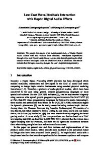
The embodiment shoWn in FIG. 1A comprises a knob 102. A user can rotate the knob 102 to perform some function, such as selecting a song from a play list on a digital music player. The knob 102 is connected to a haptic effect generator com
prising a cylinder 104. A haptic effect generator is a device
moves the pin from the ?rst position to the second position. Devices according to the present invention may also
capable of generating a haptic effect, either directly or indi rectly, on a manipulandum. The cylinder comprises four cams
include other features. For example, a membrane or other
104a-d having distinct mechanical (physical) pro?les deter 35
at least tWo haptic pro?les.
Each one of the four cams 104a-d provides a different
haptic pro?le. A haptic pro?le comprises a pre-de?ned set 40
feedback similar to a potentiometer. The second cam 1041)
accordance With the present invention. One method accord
ing to the present invention comprises generating an output
haptic pro?le and a second mechanical con?guration associ ated With the second haptic pro?le, or another con?guration.
comprising one or more haptic sensations, such as bumps, detents, stops, or other sensations. For example, in one
embodiment, the ?rst cam 10411 is smooth and provides haptic
There are a variety of methods that may be carried out in
signal operable to cause an actuator to sWitch a haptic effect generator from a ?rst haptic effect to a second haptic effect. The haptic effect generator used in such a method may com prise a ?rst mechanical con?guration associated With the ?rst
mining the haptic effect generated on the knob 102 and felt by the user manipulating the knob 102.
interfering With the operation of the haptic effect generator. As another example, a processor may be in communication With the actuator and be operable to affect a sWitch betWeen the ?rst of the at least tWo haptic pro?les and the second of the
controls the haptic pro?le, or a manufacturer performs a mode
selection before installing the device.
landum, such as a button. The manipulandum comprises a surface, a portion of Which de?nes a hole. The device also comprises a pin con?gured to move through the hole from a ?rst position at or beloW the surface to a second position above the surface. An actuator in communication With the pin
structure may be placed proximate to the surface of the manipulandum such that it may prevent foreign matter from
tiple stable mechanical con?gurations or a loW-poWer device. In one embodiment of the present invention, haptic sensa
45
(FIG. 1B) includes detents 10319 that are shalloW and closely spaced, providing haptic feedback similar to What is often provided by conventional audio volume controls. The third cam 1040 includes a detent in the center of rotation and is
otherWise smooth, providing haptic feedback similar to What is often provided by conventional tone, balance, or fader controls of an automotive audio system. The fourth cam 104d 50
(FIG. 1C) includes four deep detents 104d spread evenly
A method according to the present invention may also com
betWeen tWo hard stops 105d, providing feedback similar to
prise receiving an input signal associated With a haptic effect
What is often provided for a fan control of an automotive climate control system. Another example of a cam including
sWitch. The input signal may be associated With a device state or other data. In one embodiment of a method according to the
present invention, the actuator comprises a DC motor. The
output signal may comprise any suitable signal. For example, the output signal may comprise a positive pulse. The level of the pulse may be proportionally higher than a previous maxi
protrusions 103x is shoWn in FIG. 1D. 55
a ball 112. The ball 112 presses on one of the cams 104a-d.
The pressure of the ball 112 on the cam 104a-d provides the haptic effect. When the ball 112 is in a cam 104a-d, the
mum. As another example, the output signal may comprise a
negative pulse, proportional to the current level of friction,
60
and a positive pulse of a magnitude proportional to the desired level of friction. Embodiments of the present invention may also include a computer-readable medium encoded With code to carry out such methods. Any suitable code type may be used.
BeloW, systems and methods in accordance With the present invention are described With reference to FIGS. 1-8.
In the embodiment shoWn, a slider 106 on a square shaft
108 holds a lever comprising a leaf spring 110 terminated by
65
mechanism provides a stable mechanical con?guration. The mechanical con?guration does not change until the actuator acts upon the haptic effect generator. In another embodiment, a spring-loaded pin is used instead of the lever. In the embodiment shoWn in FIG. 1A, an actuator deter mines the position of the slider 106. The actuator comprises a solenoid 114 With four coils 116a-d and one iron core 118. The iron core 117 is connected to the slider 106 by a rod 120.
US 7,567,243 B2 5
6
Activation of a coil 116a-d neighboring the present position of the core 118 changes the position of the slider 106, and
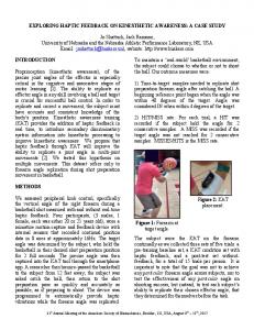
embodiment shoWn in FIG. 2, a resistive actuator With pro
grammable varying friction consumes poWer only When the friction is changed. In the embodiment shoWn, a knob (not shoWn) is connected to a shaft (not shoWn). The shaft is positioned in the center 202
consequently moves the ball 112 from a ?rst cam 11411 to a
second cam 114b, and thereby changes the haptic feedback provided to the user. The coils 16a-d are connected to a poWer
of a single part shoe brake 204 so that When the brake is applied, it resists rotation of the shaft. A motor 206, such as a
supply (not shoWn) and a sWitch (not shoWn). The sWitch may be a processor or may be connected to a processor.
Although FIG. 1A illustrates an embodiment for providing haptic effect pro?les to a knob, a variety of similar devices
DC motor, turns a screW 208 to actuate the brake 204. The
brake has tWo ends 210, 212. When the motor 206 turns the screW 208, the tWo ends 210, 212 are pulled together or
could operate on this principle, including, for example, slid ers, push buttons, and joysticks. In various embodiments, a
pushed apart along line 214. When the tWo ends 210, 212 are
mode selector, a processor, or some other control means may
pulled together, the brake 202 tightens around the shaft (not
control the actuator. Similarly, the solenoids and plunger system used to sWitch betWeen the haptic pro?les is used for illustrative purposes only. In other embodiments of the present invention, any suitable mechanical system having a
shoWn) to provide a resistive force. When the tWo ends 210, 212 are pushed apart, the resistive force abates. The pitch of the screW 208 is such that When no poWer is applied to the
motor 206, the friction exerted by the brake 204 remains approximately constant and stable. The level of friction applied by the brake 204 is determined by the cycles of current applied to the motor 206. It can be
?nite number of stable con?gurations coupled With one or more actuators able to displace the system into any of these
stable con?gurations could be used according to the needs of particular applications. Various types of actuators may be utiliZed, including the exemplary actuators described herein.
20
One embodiment of the present invention comprises a pro cessor in communication With the actuator and programmed to provide feedback based on parameters, such as user input
and environmental factors, provided by sensors. Processors
precisely determined in open loop by taking advantage of the hysteretic properties of friction. The principle is to apply a different signal pro?le depending on Whether friction has to be increased or decreased.
25
Applying pulses to the motor 206 achieves the controlling of the amount of friction applied to the manipulandum. The
shape of the pulses is not important, only the magnitude of their extrema is. By convention, a positive pulse tightens the
can comprise, for example, digital logical processors capable of processing input, execute algorithms, and generate output as necessary to control the actuator in response to input. Such
screW 208. To increase friction by a given amount, the level of
controllers may comprise a microprocessor, an Application
the pulse must be proportionally higher than the previous
Speci?c Integrated Circuit (ASIC), and state machines. Such processors comprise, or may be in communication With,
maximum. To decrease friction, a negative pulse if ?rst applied proportionally to the current level of friction (to
media, for example computer readable media, Which stores
reset), followed by a positive pulse of the desired magnitude.
instructions that, When executed by the processor, cause the processor to perform the steps described herein as carried out,
Because of the small masses and small movements involved, the time scale of these pulses can be of milliseconds. Other
or assisted, by a processor.
30
35
control methods may be utiliZed as Well.
40
In the embodiment shoWn in FIG. 2, the amount of friction applied to a control remains constant betWeen control pulses. For example, in one embodiment of the present invention, a knob is used to select the volume and frequency for a radio receiver. Control of the volume does not require a ?ne degree
Embodiments of computer-readable media comprise, but are not limited to, an electronic, optical, magnetic, or other storage or transmission device capable of providing a proces sor, such as the processor in a Web server, With computer readable instructions. Other examples of suitable media com
of accuracy. Selecting a frequency requires a ?ner grain of
prise, but are not limited to, a ?oppy disk, CD-ROM,
magnetic disk, memory chip, ROM, RAM, ASIC, con?gured
control to achieve the desired accuracy. When a user selects a
processor, all optical media, all magnetic tape or other mag
function, such as the volume control mode, a pulse is sent to the actuator that results in loW friction, i.e., the screW loosens or resets and then provides minimum friction. The user is able
netic media, or any other medium from Which a computer processor can read. Also, various other forms of computer
45
readable media may transmit or carry instructions to a com
to quickly rotate the dial and make large changes in volume.
puter, comprising a router, private or public netWork, or other
HoWever, the user is less able to make ?ne adjustments to the volume. When the user selects the frequency control mode, a pulse is sent to the actuator that causes a greater level of
transmission device or channel. The embodiment shoWn in FIG. 1A utiliZes a solenoid
actuator. Another embodiments of the present invention
50
shoWn in FIG. 1E includes a DC motor 119 as an actuator and
friction to be applied to the shaft of the knob. By applying friction, the brake sloWs the movement of the shaft doWn;
uses a pin 113 (instead of a ball 112). In other embodiments,
such a control pro?le alloWs a user to more easily exercise
actuators incorporating shape memory alloy (SMA) ?bers,
precision in selecting a frequency.
modulated signal. Useable actuators are available from a
FIG. 3 is a ?owchart illustrating a method for controlling the actuator illustrated in FIG. 2 in one embodiment of the present invention. In the embodiment shoWn, a knob or other
variety of sources, including Nanomuscle, Inc. of Antioch,
manipulandum provides a mechanism for scrolling through a
Calif. (WWW.nanomuscle.com). Other types of actuators may
list of names in an address book application or in a music play list of a digital music player. Each time the cursor encounters
such as NiTi ?bers, provide actuation. Such actuators can be
activated in single pulse mode using a simple pulse Width
also be utiliZed, such as pieZo or polymer actuators. In one embodiment, an actuator utiliZing mechanical ratchets to dis
55
60
place the haptic effect generator into its multiple stable con ?gurations, Which are also referred to as rest positions, is used. FIG. 2 is an illustration of a resistive actuator in one
embodiment of the present invention. Conventional devices,
an item in the list, the actuator is controlled to cause a tactile
pulse to be experienced by a user. In the embodiment shoWn, poWer is spent only to increase or decrease the applied fric tion. When the user moves the knob such that the cursor encoun
such as electromagnetic poWder brakes, With programmable
ters a feature, Which is to be tactilly represented, such as a detent, step 308 detects the event corresponding to the cursor
friction consume poWer during nominal operation. In the
entering the feature. If this event is detected, then friction
65
US 7,567,243 B2 7
8
level is increased at step 310 by sending a pulse to the actuator 206. If the event of exiting the feature is detected at step 312, the friction is decreased at step 304 by resetting the device With a negative pulse su?icient to reduce the friction below the nominal level, and then by bringing the friction back to the nominal level With a positive pulse of the desired magnitude. The process continues While the user is utiliZing the address book mode. In this manner, the user is able to quickly scroll through a long list of names and addresses and is also able to
pins (410) 512. lfthe device is noW on, the processor sends a
signal to the actuator (414) to retract the pins (410) 514. The
process then ends 516. Again, solely by touching the button (402), the user is able to determine the state of Whatever system or device the button (402) controls. For example, in one embodiment, a button With an actuator
according to the present invention controls the rear defroster of an automobile. Conventional buttons for controlling the rear defroster of an automobile often comprise an indicator
precisely place a cursor or other indicator on an individual
light, Which is illuminated When the defroster is on. With
entry in an address book list. FIGS. 4 and 5 are schematic diagrams illustrating a pro grammable surface feel in one embodiment of the present
defro sters that turn themselves off after a time period, the user must look at the indicator light to determine Whether or not
the defroster is on. A button according to the present invention
invention. Such an embodiment is capable of providing pro
alloWs the user to determine Whether or not the rear defroster
grammable surface feel in various manipulanda, including,
is on simply by touching the control button. If the defroster is
for example, to a push button or other device designed to engage contact With a user’s skin during operation. The button 602 comprises a surface 604. The surface 604 has an array of holes matching a plurality of teeth of an
on, the pins are extended, and the user is able to feel the pins through the surface membrane of the sWitch. The embodiment shoWn in FIGS. 4, 5, 6, and 7 is merely exemplary of hoW surfaces may be altered by embodiments of the present invention. Embodiments of the present invention
element 614 Which can have tWo stable con?gurations, one in Which the teeth are protruding as in FIG. 4 and the other in
20
may provide numerous other surface alterations as Well.
Which the teeth are recessed as in FIG. 5. The sWitch from one
An embodiment of the present invention may be advanta
con?guration to the other is accomplished by activating one ofthe solenoid coils 606 or 608 acting in the iron core 610. An elastic membrane 612 is use to maintain the element 614 in one of the tWo stable con?gurations. FIGS. 6 and 7 are schematic diagrams illustrating a pro
geously implemented in applications Where loW poWer con 25
volume, fast-forWard/reWind (shuttle) and frame-by-frame
grammable surface feel in another embodiment of the present invention. In the embodiment shoWn, a button 402 has a surface 404. The surface 404 of the button 402 has an array of
holes, including hole 406. Located beneath the button surface 404 is an element 410 including a plurality of pins corre sponding to the holes in the surface 404. A slider 412, Which is activated by a solenoid 414, has tWo stable positions. The left position illustrated in FIG. 6 alloWs the array of pins to
30
and sixty degrees through a series of equidistant detents. 35
40
45
manipulandum, a membrane (not shoWn) is positioned above-the pins. The membrane alloWs a user to feel the pins
and prevents dirt, dust, or other foreign matter from entering 50
mid-point comprises a neutral position. Embodiments of the present invention may be pre-pro grammed. For example in one embodiment, a knob according to the present invention comprises three programmable pro ?les. The manufacturer of the knob delivers a shipment of
different functions, requiring distinct pro?les for each or 55
(410) retracted, the user can determine that the device is off Without looking at the button or any other indicator.
betWeen many of these distinct functions. The manufacturer is able to program the knob to provide a speci?c pro?le upon installation of the knob by applying poWer to the actuator. The knob retains this pro?le unless or until the pro?le is later changed. In the meantime, the device requires no poWer to
impart the desired haptic effect. 60
Embodiments of the present invention may be used alone or in combination With other loW-poWer haptic feedback devices, conventional mechanical devices, and active and passive/resistive haptic feedback devices. For example, a knob having various loW-poWer detent effects may also be in
65
communication With a vibratactile actuator, for example, an
indicating that the device is noW on 508. The processor deter mines Whether the device is noW on or off by evaluating a data
value associated With the signal 510. For example a value of “1” may indicate that the device is on; a value of “0” may indicate that the device is off. If the device is noW off, the processor sends a signal to the actuator (414) to extend the
toggle sWitch comprises a third detent at approximately the mid-point of its range of motion. In one such embodiment, the
these knobs to an automobile manufacturer. The automobile manufacturer uses the same type of knob to perform many
actuator (414) to retract the pins (410). When the user places a ?nger on the membrane above the button (402) With the pins When the user depresses the button (402), turning on the device, the processor receives a device status change signal
Which is further connected to an actuator. The toggle sWitch is able to move in one plane betWeen tWo stops. In a ?rst pro?le, the toggle sWitch is able to move throughout its range of motion With no detents. In a second pro?le, the toggle sWitch comprises a detent at or near one end of its range of motion
selectively engaging one or several cams as in the knob
For example, if a processor determines via a sensor signal that a device is turned off, the processor sends a signal to the
One embodiment of the present invention comprises a toggle sWitch connected to a controllable pro?le element,
and at or near the second end of its range of motion, operating like a conventional tWo -Way light sWitch. In a third pro?le, the
example above.
the mechanism an interfering With movement of the pins. FIG. 8 is a ?owchart illustrating a process for controlling the operation of the actuator shoWn in FIGS. 6 and 7 in one embodiment of the present invention. When a device changes state, this state is sent by a signal to the programmable button.
to move freely betWeen to stops, a minimum and a maximum.
When the user selects the jog control mode, the actuator
When the slider 412 is in the position illustrated by FIG. 7, the button surface 404 feels rough because the projects extend
In one embodiment utiliZing holes in the surface of a
picture (jog) control. When the user selects the volume con trol mode, the actuator engages a pro?le that alloWs the knob
engages a pro?le that alloWs the knob to move three hundred
move freely With the surface of the button 402. The button surface 404 feels smooth When depressing the button 402.
beyond the surface. In another embodiment, an actuator shifts the array of pins sideWays With respect to the surface rather than indenting the skin. This can easily be accomplished by
sumption is critical, such as in a remote control. In one embodiment of the present invention in a remote control, a knob alloWs the user to control multiple functions, such as
eccentric rotating mass (ERM) actuator, Which imparts a vibration on the knob under certain conditions.
US 7,567,243 B2 9
10
The foregoing description of the embodiments of the invention has been presented only for the purpose of illustra
an actuator in communication With the folloWer and oper able to move the folloWer betWeen the ?rst surface and
tion and description and is not intended to be exhaustive or to
the second surface, Wherein the actuator comprises a
limit the invention to the precise forms disclosed. Numerous modi?cations and adaptations thereof Will be apparent to those skilled in the art Without departing from the spirit and scope of the present invention. That Which is claimed: 1. A device comprising: a surface having a ?rst channel comprising a ?rst plurality of surface features, the ?rst plurality of surface features con?gured to provide a ?rst haptic pro
member formed of shape memory alloy. 12. A device comprising: a haptic effect generator operable to provide a ?rst haptic pro?le associated With a ?rst mechanical con?guration and a second haptic pro?le associated With a second
mechanical con?guration; and an actuator in communication With the haptic effect gen
erator and operable to sWitch the haptic effect generator betWeen the ?rst haptic pro?le and the second haptic pro?le, Wherein the actuator comprises a member
?le, and a second channel substantially parallel to the ?rst channel and comprising a second plurality of surface features, the second plurality of surface features con?gured to
formed of shape memory alloy. 15
provide a second haptic pro?le; a folloWer con?gured to folloW the ?rst channel and the
second channel; and an actuator in communication With the folloWer and oper able to move the folloWer betWeen the ?rst channel and
20
the second channel, Wherein the actuator comprises a
member formed of shape memory alloy. 2. The device of claim 1, Wherein the surface comprises the surface of a cylinder. 3. The device of claim 2, Wherein the ?rst channel com prises a ?rst cam and the second channel comprises a second
13. The device of claim 12, further comprising a manipu landum in communication With the haptic effect generator. 14. The device of claim 13, Wherein the manipulandum comprises one of a knob, a slider, a push button, and a joy stick. 15. The device of claim 12, Wherein the haptic effect gen erator comprises: a cylinder comprising at least tWo cams, each of the tWo cams having different mechanical con?gura tions; and a lever operable to engage at least one of the at least tWo cams.
25
16. The device of claim 15 Wherein the lever comprises a
spring-loaded lever. 17. The device of claim 15, Wherein the lever comprises a
spring-loaded pin.
cam.
18. The device of claim 12, Wherein the haptic effect gen
4. The device of claim 1, Wherein at least one of said ?rst
plurality of surface features comprises a protrusion.
30
19. The device of claim 18, Wherein the brake comprises a
5. The device of claim 1, Wherein at least one of said ?rst
single part shoe brake.
plurality of surface features comprises a stop. 6. The device of claim 1, Wherein at least one of said ?rst
plurality of surface features comprises a depression. 7. The device of claim 1, Wherein the folloWer comprises
35
one of a pin, a paWl, and a lever. one of a solenoid and a DC motor. 40
comprises one of a knob, a slider, a push button, and a joy stick.
11. A device comprising: 45
tures, the ?rst plurality of surface features con?gured to provide a ?rst haptic pro?le, and a second surface substantially parallel to the ?rst channel and con?gured to move With the ?rst surface, the second surface comprising a second plurality of surface fea
tures, the second plurality of surface features con?gured to provide a second haptic pro?le;
22. The device of claim 12, Wherein the haptic effect gen erator is operable to alter a surface of the manipulandum. 23. The device of claim 22, Wherein the haptic effect gen erator comprises a pin positioned beloW the surface of the
manipulandum.
10. The device of claim 9, Wherein the manipulandum
a ?rst surface comprising a ?rst plurality of surface fea
20. The device of claim 18, further comprising a screW operable to vary a friction exerted by the brake. 21. The device of claim 20, Wherein the actuator comprises a DC motor operable to turn the screW.
8. The device of claim 1, Wherein the actuator comprises
9. The device of claim 1, further comprising a manipulan dum in communication With said surface.
erator comprises a brake.
24. The device of claim 23, Wherein the haptic effect gen erator further comprises a slider operable to project the pin above the surface of the manipulandum. 25. The device of claim 23, Wherein the actuator comprises a solenoid.
26. The device of claim 22, further comprising a membrane
proximate to the surface of the manipulandum. 50
27. The device of claim 12, further comprising a processor in communication With the actuator and operable to affect a
sWitch betWeen the ?rst of the at least tWo haptic pro?les and the second of the at least tWo haptic pro?les.
a folloWer con?gured to folloW the ?rst surface and the
second surface; and
*
*
*
*
*