taken to ensure safe operation. Keywords â Autonomous Systems, Railway, Systems of Systems,. Hazard Analysis, Risk Management. I. INTRODUCTION.
SysCon 2008 – IEEE International Systems Conference Montreal, Canada, April 7–10, 2008
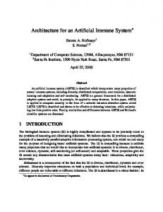
System Architecture and Risk Management for Autonomous Railway Convoys 1
Christian Henke1, Matthias Tichy2, Tobias Schneider1, Joachim Böcker1, Wilhelm Schäfer2 Power Electronics and Electrical Drives, University of Paderborn, Warburger Str. 100, 33098 Paderborn, Germany 2 Software Engineering Group, University of Paderborn, Warburger Str. 100, 33098 Paderborn, Germany
Abstract – The RailCab project envisions autonomous railway vehicles which drive in convoy without mechanical coupling. The RailCabs can dynamically and autonomously build and dissolve convoys. This enables an on-demand use of these vehicles while retaining the cost and ecological advantages of public transport. The development of such system has to be rigorous with respect to safety issues in order to avoid loss of lives and other damages. In this paper we present an overview about the system architecture of the RailCab prototype on the test track as well as the actions to be taken to ensure safe operation. Keywords – Autonomous Systems, Railway, Systems of Systems, Hazard Analysis, Risk Management
I.
autonomously driving vehicles. The RailCab vehicles are designed in a modular way. For driving and braking a doubly-fed linear motor is used. An active suspension and tilt module provides high passenger comfort. Additionally, the RailCabs are equipped with an active steering module, which enables joining and leaving a convoy using passive switches. The doubly-fed linear drive consists of two motor components. One part is located at the track; the other one is part of the vehicle. Thus, even a single RailCab is a distributed system. We use a layered approach for the design of the system architecture.
INTRODUCTION
In terms of ecological values, public transport by bus or railway is deemed superior to individual transport by car. Unfortunately, individual transport clearly provides more flexibility and comfort for the passenger. The RailCab project was founded at the University of Paderborn in 1998 in order to develop a new railway system that features the advantages of both techniques in terms of cost and fuel efficiency as well as flexibility and comfort [1]. The novel system is characterized by autonomous vehicles operating on demand instead of trains according to a fixed schedule. The doubly-fed linear motor allows convoy driving without mechanical coupling [2]. This allows increasing amounts of vehicles on a track as well as energy savings. The RailCab project envisions networks of thousands of RailCabs which are acting autonomously and interacting with each other. Consequently, it is a good example of a system of individual and autonomous systems. For real-life validation of the complex mechatronic system, a test track in a scale of 1:2.5 was built at the University of Paderborn in 2002. At present, two railway vehicles, so-called RailCabs, can be operated simultaneously. In the next section, the system architecture of a single RailCab is introduced. Section 3 describes the autonomous convoy operation and the resulting architecture of the distributed system. The communication architecture of the test track is presented in Section 4. The autonomous convoy operation is safety-critical. The hazard analysis and the resulting system design are described in Section 5. We conclude with an outlook on future work in Section 6. II. RAILCAB ARCHITECTURE The novel railway system is characterized by small,
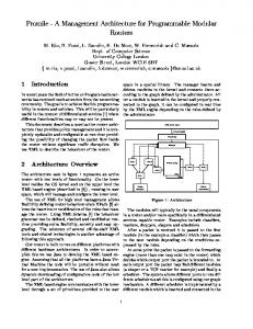
Fig. 1. Operator Controller Module (OCM)
The Operator Controller Module (OCM) [3] represents the control architecture of a vehicle as shown in Figure 1. It is partitioned into three main components: The controller links the physical elements and performs the controlled process depending on the desired operation mode (e.g. distance control for convoy operation). The operation mode is controlled by the reflective operator. That part includes also the risk management and the generation of reference set
values for the controller. Both components are operating under hard real-time constraints and are safety-critical. The cognitive operator deals with operating point optimization and logistics under soft real-time requirements. Reliability and safety especially in case of emergency situations have to be provided in convoy mode as well as in all other situations. A proper control system for autonomous operations is mandatory [2]. Additionally, the occurrence of system faults has to be considered during the system design process. Therefore, a modular safety system has been integrated into the reflective operator component to handle hazardous incidents. Indicated failures are evaluated by a hazard list depending on the operation mode [2]. In case of a hazard occurrence, set values will be adapted by the reference generator to transfer the vehicle from an undesired to a safe state in order to provide a fail-safe operation (see Section 5). III.
ARCHITECTURE OF A RAILCAB CONVOY
The concept of convoy driving envisions that vehicles align with others during driving without mechanical coupling. The doubly-fed linear motor enables distance adjustment between vehicles even on the same stator section. Additionally, forming and dissolving of convoys is possible when moving. Furthermore, the active steering allows dissolving of convoys in combination with the passive track switch. Therefore dynamic convoy driving is possible, which offers the following potential to be utilized: •
Increasing the track capacity
• Decreasing the power consumption Best results can be achieved, if rapid approach processes and small distances between the vehicles are realized. To meet these demands information about other vehicle positions, operational profiles and system status are required. The convoy control is divided into controlling acceleration, velocity, position and distance of the RailCabs as well as the message-based coordination, whether a convoy should be built and when it should be dissolved. This separation of concerns is reflected by the OCM architecture (see Fig. 2). The controller contains the control algorithms whereas the message-based convoy coordination is included in the OCM’s reflective operators of the two RailCabs. The reflective operator contains also the configuration control. It activates the controller to be used in a certain state of the convoy coordination. Each individual system is modeled as a hierarchy of OCMs. Distributed systems like a RailCab convoy do not share a common OCM but use message-based protocols between the reflective and cognitive operators to coordinate their behavior to satisfy a common goal as in our example the safe convoy operation.
Fig. 2. OCM Structure for two RailCabs in convoy mode including the real-time coordination pattern with safety condition
IV.
COMMUNICATION INFRASTRUCTURE
A. Communication Topology The vehicles are driving autonomously on the test track. Only the operational profile is transmitted via radio communication by an operator from a control room, while the control of the drive and the other on-board components are running on the vehicle itself. The vehicle sends its position and the requested set points for the track-sided motor part via a second communication channel realized by radio modems using bi-directional transmissions in 2.4 GHz ISM band. Additionally, a third radio communication provides data transfer between the vehicles operated in the same area. This wireless communication includes continuous information like speed and position, which are needed for the distance control. Additionally, a message-based information exchange for initialization and handling of the convoy operation is required. Both communication paths are using the wireless communication network, which is employed between the different RailCabs in a convoy. The resulting communication topology of the test facility is illustrated in Figure 3.
Fig. 3. Communication topology of the test bench
B. Communication in a Convoy The communication between the RailCabs is crucial for a safe convoy operation. Thus, we present it in the following in more details. Wireless communication suffers from value as well as omission faults. As we have two different types of communication between the vehicles with different requirements (periodical and on-demand), we use two data link layers (see Fig. 4). The first one only masks value faults whereas the second one additionally masks omission faults. These two data link layers only deal with sporadic faults. If the communication breaks down completely, each RailCab of a convoy will start a safe braking procedure (see Section 5). Figure 4 shows the architecture for the communication between two RailCabs. We employ Linksys WRT54g routers for the wireless communication between the RailCabs. The routers are connected via DS 4502 Ethernet boards to the RailCab execution hardware. The communication on this lower level uses UDP/IP. UDP does already provide mechanisms to detect value faults and discard faulty packets. A value fault is therefore transformed into an omission fault.
processed by the reflective operator or the data link layer. This data link layer is an implementation of standard protocols from the literature [7]. C. Data Protocol The employed UDP-protocol includes no timing information. For evaluating the time behaviour clock synchronization is useful. The signal of a vehicle mounted radio synchronized clock (DCF77 module), which provides an accuracy of 4 ms, is integrated into to the communication protocol as a time stamp. Thus data packet overtaking and high latency can be identified. The inter-vehicular communication has a cycle time of 20ms for the bi-directional data transfer. The communication protocol contains continuous values for convoy control like speed and position. Furthermore, system status is sent continuously, which includes information about status of the linear drive, the on-board energy system and possible system faults. The communication protocol is divided into protocol overhead needed for validating received data and the user data. Table 1 shows data, data type and length of the protocol. Table 1. Communication protocol
Data
Data type
Length [Byte]
watchdog BCH code clock position track section velocity stator current stator frequency state acknowledge id message parameter
uint(8) double double double uint(8) double uint(8) uint(8) uint(8) unit(8) uint(8) uint(8) double
1 4 4 4 1 4 1 1 1 1 1 1 4
overhead
continuous data
messagebased data
Σ 28
V. HAZARD ANALYSIS & RISK MANAGEMENT IN CONVOY MODE Fig. 4. Communication of two RailCabs in convoy mode
This behavior is appropriate for the continuous communication for convoy control since sporadic omission faults are handled by the control algorithm. This behavior is inappropriate for the message-based communication between RailCabs which is concerned with building and dissolving convoys since the communication protocol depends on the reliable exchange of messages. A message lost by an omission fault would result in a protocol deadlock. Consequently, we implemented a data link layer which specifically deals with sporadic omission faults by resending data packets until an acknowledgement of the packet reception has been received. Messages are buffered in incoming and outgoing packet queues until they are
As hazards during convoy operation may cause catastrophic results, the requirements on the developed system and the development process are high. Performing a hazard analysis is mandatory for safety-critical systems. The resulting hazards must be either eliminated, reduced, controlled or the associated damage minimized [10]. A hazard can be eliminated by eliminating the hazardous state from the system. A hazard is reduced when the likelihood of its occurrence is reduced e.g. by reducing the likelihood of the conditions which lead to the hazard. A hazard is controlled if the likelihood of it leading to an accident is reduced e.g. by detecting a hazard and transferring to a safe state. Finally, the consequences or losses of an accident may be minimized.
In this section, we first present an extract of the hazard analysis for the RailCab convoy. Thereafter, we describe different actions we took in order to reduce the likelihood of a hazard as well as to control it. A. Hazard List and Fault Tree Analysis for Convoy Mode Central point of the risk management is the early identification of hazardous incidents. We performed a hazard analysis on the system as well as the subsystem level. The result is a hazard list. The hazard analysis has been performed on the functions of the subsystem in accordance with [9]. This approach considers the system as a closed control loop for a clearer understanding (see Figure 5). It maps each malfunction of a subsystem to the parts of the closed control loop.
•
Absolute braking distance: d < d abs
• Relative braking distance: d < d rel The fault tree for hazard collision is composed of different branches, representing on the one hand the operating mode and the braking distances and on the other hand system failures. Figure 6 shows an extract of the fault tree for the hazard collision with two RailCabs.
Fig. 6. Fault tree for hazard collision (following vehicle) Fig. 5. Closed control loop for functional analyses
For this purpose, the system is divided into four sections: Physical execution, value detection, configuration control and setting of driving values. Table 2 shows an extract of functional faults in accordance to the resulting accidents for the regarded application. Table 2. Hazard list and resulting accidents (extract)
Process
Malfunction detection of position (velocity)
signal detection
physical process reference generator
configuration control
fault detection of radio communication detection of distance to leader radio communication distance control drive control calculation of distance references calculation of references for linear drive selecting convoy mode status control of radio communication status control of linear drive
Accident derailment, collision collision collision collision collision derailment, collision collision derailment, collision collision collision derailment, collision
In this paper, we focus only on the fault tree for the hazard collision in convoy mode. The absolute distance dabs is the maximal braking distance of one vehicle whereas the relative braking distance drel is the difference of the maximal braking distances if both follower and leader RailCab brake. Three cases are distinguished for distance control in convoy mode based on these braking distances [2]: • Safe distance: d ≥ d abs
The combinations of events which result in the hazard are the results of the fault tree analysis. The following sections contain our actions against these combinations. We reduce the likelihood of the hazard occurrence by eliminating the hazardous event combination “Leader RailCab in Convoy mode” and “following RailCab in NoConvoy mode” by the behavioral specification and subsequent formal verification. We control the hazard by reacting to the faults of the system components. We distinguish severe and minor faults. Severe faults require fail-safe actions whereas minor faults merely result in a degraded operation. B. Hazard Reduction It is a hazardous situation when the front vehicle (Leader) is in the NoConvoy state whereas the rear vehicle (Follower) is in the convoy state according to the hazard analysis. This is hazardous since the front vehicle might brake with maximum force believing it has enough distance to the following vehicle due to the fact that it is not in convoy mode although the rear vehicle is driving in a close distance. In order to reduce the likelihood of the hazard we specified the software in such a way that this state combination is impossible. We use model-based formal verification techniques [4, 5] to automatically check whether this state combination is reachable by the specified software behavior. Systems of systems with thousands of elements and dynamic structural changes as envisioned in the RailCab project do not allow the specification and verification of the whole system. Instead compositional approaches have to be employed where parts are precisely defined. Each system part is individually specified and verified with respect to safety conditions. The compositional approach then guarantees that
the whole system is safe with respect to the safety conditions when the system is correctly assembled from the base parts.
Fig. 7. Real-Time coordination pattern for the convoy coordination
We employ the compositional approach of [5] for the design and verification of the reflective operator. The approach is based on the notion of real-time coordination patterns (see Fig. 7). These patterns specify distinct coordination activities between system elements – the mentioned convoy operation, coordination between local and regional supervisors, coordination with track infrastructure, etc. These patterns are individually verified with respect to safety conditions. FrontRole
front vehicle whereas the lower figure shows the behavior of the rear vehicle. The coordination behavior is based on a simple message exchange protocol which is non-deterministically started by the rear vehicle by sending a convoy proposal to the front vehicle which plays the front role in this coordination behavior. The front vehicle either refuses or accepts this convoy proposal. Both vehicles change into the convoy state in the second case. The behavior for dissolving a convoy is similar. It has been formally verified using model checking that the above specified hazardous state combination is not possible even in the case of arbitrary communication faults [5]. The reflective operators of the system elements reuse and refine the behavior specified in the presented real-time coordination pattern as well as others. If the patterns are correctly refined the safety conditions are then guaranteed for the whole system [5]. The verified specification of the reflective operator has been refined and implemented using the Matlab/Simulink/Stateflow environment and its real-time code generation facility for the test bench. The refinement of the specified abstract behavior did include exchange of additional messages which are used to decide on the convoy join position and join velocity as well as the emergency and normal braking forces. C. Hazard Control
noConvoy / rearRole.convoyProposalRejected
default
rearRole.convoyProposal /
rearRole.breakConvoy /
wait
/ rearRole.startConvoy
Some event combinations for the hazard cannot be eliminated. Therefore, we control the hazard by transferring the system into a safe state whenever a hazard is detected. The hazard control is performed by the reflective operator of the OCM RailCab as shown in Figure 9.
Convoy wait
/ rearRole.breakConvoyProposal
default
OCM RailCab
rearRole.breakConvoyProposalRejected /
Configuration control
RearRole
Hazard reaction
Reference generator
frontRole.convoyProposalRejected /
default
/ frontRole.convoyProposal
Vehicle Components
Reflective Operator
wait
System status Hazard occurrence No hazard
OCM Drive / Brake
Hazard list System status
System analysis
OCM Power Supply OCM Guidance
OCM Spring / Tilt Set values
Sensor signals
Motion control / Mechanical brake
frontRole.startConvoy
convoy
frontRole.breakConvoyProposal / frontRole.breakConvoy
Fig. 9. Hazard handling for motion control
default
frontRole.breakConvoyProposal / frontRole.breakConvoyRejected
Fig. 8. Behavior for two vehicles concerning the convoy coordination.
Figure 8 shows the behavior of two vehicles which is specified in the real-time coordination pattern “ConvoyCoordination” [5]. We consider here only the simpler case of a two vehicles convoy (see [6] for a presentation of the coordination behavior for convoys with more vehicles). The upper figure shows the behavior of the
The first step is the system analysis, which is separately executed for each component resulting in a simple state description. Three states are defined. Either the component is operating, restricted in terms of functionality, or defect. Therefore only the system state is submitted to the higher level system. The system analysis of the motion control is directly executed inside the OCM RailCab and considers the state of the inter-vehicular communication device as well as distance information to nearby RailCabs in case of convoy mode.
By means of the system information of subordinated OCMs, a comparison with the predefined hazard list [9] results either in hazard detection or in regular operating mode. In case of hazard occurrence the configuration control decides hazard reactions like adaptation of set values or emergency brakes in order to convey the system from an undesired to a safe state. This is implemented by the vehicle safety system. All safety providing components and functions have to be installed redundantly. Two levels for the system safety can be distinguished due to the communication system described above. The central track sided host system supervises all vehicles by means of the exact position and velocity data needed for activating the stator sections. The other local automatic operating system is located on-board the vehicle within the reflective operator as described in Section 2. A further safety system is based on an environment detection device which collects data about objects close to the vehicles. Distance information of other vehicles being in the measuring range is of particular importance. A differentiation of the measured distances provides velocity information. Hence, additional static obstacles can be identified. Measurement devices are employed, as utilized typically in automobile applications, based on ultrasonic, infra-red and radar technology to cover areas from close range up to large distances. However, contrary to the communication device, important information about system status cannot be generated. Therefore, the environment detection system is only used for validating information received via the radio communication or in case of communication failures.
Fig. 10. Vehicle safety concept for convoy operation
All data is collected in the reflective operator, which evaluates the current situation. The risk management identifies disturbances, resulting in adapted reference values or requested emergency brakes (see Figure 10). Inside the reflective operator, fault detection mechanisms are implemented. If transmission faults of the inter-vehicular communication arise, the message based data communication repeats its protocol until a fault-free communication has been ensured. However, for distance control continuous position and velocity data are required. With a Kalman filter observation of position can be achieved. The Kalman filter is
a stochastic observer, which estimates the current position depending on the past velocity trajectory. With every incoming position data, the estimation error will be corrected. In order to detect faults and to describe the state of the system, all signals, components and modules have to be checked continuously during runtime. A plausibility check will be conducted with measured data, including a verification of value margins and gradients. In addition, a model-based plausibility approach is useful [8]. Therefore a validated model runs parallel to the real plant, in order to check the variations between calculated and measured system behaviour (see Figure 11).
Fig. 11. Structure of model-based fault detection
In case of clearly faulty measures values, the values will be discarded. Otherwise, the input signals of the model will be updated. This monitoring function is not only useful for validating sensor signals. Functionality checks of the synchronization of the distributed drive train, which cannot be directly measured, are possible. With a model of the track and the model of the vehicle-sided and track-sided motor and their on-board the vehicle calculated current references, position and velocity trajectories can be simply estimated. With this method functionality faults can be reliably identified. Further fault detection mechanisms are operating with redundant sensors. For measuring the vehicle position four wheel-mounted encoders are applied. After value margin and gradient checks only the best two encoder signals will be used. However the most effective method is diverse redundancy as used for getting distance information about vehicles in a convoy by radio communication and environment detection (see Figure 10). The convoy mode envisions that vehicles operate in convoy mode with distances of only few centimetres. However, if a hazardous situation has been identified, the configuration control outputs a hazard reaction like dissolving the convoy or increasing the distance. Corresponding to the branches of the fault tree, hazard reactions have to be defined. The branch, which covers faults within the message-based communication, can be disregarded because of the design process. However, mentioned severe faults cannot be excluded and will cause an emergency brake. The RailCabs agree on their behavior in these emergency cases before convoy formation using the message-based communication. In the following, three example cases will be presented: A – Communication failure: If the communication fails for over 100ms, both RailCabs enter an emergency state and exit the convoy mode. The leading RailCab remains in a speed control mode whereas the following RailCab performs an emergency brake (see Figure 12). This is a fail-safe state.
RailCab 2
RailCab 1
convoy
convoy a: data (cf. Section 4.C)
{b.sendTime – a.sendTime = 10ms}}
counter := currentTime data
counter := currentTime
{b.receiveTime – a.receiveTime = 10ms}}
b: data data
counter := currentTime
[currentTime – counter > 100ms]
data
[currentTime – counter > 100ms]
watchdog.emergency
C – Restricted communication and restricted drive and brake module of the leader: The occurrence of this combination of two minor faults results in remaining in convoy mode but with increasing distance references and decreasing velocity. Driving within the relative braking distance is too unsafe. Therefore both vehicles will start decelerating. According to the agreement the follower decelerates faster than the leader. The absolute braking distance and the final speed of the leader will be adjusted by the follower. An acknowledgement for the braking procedure will not be awaited (see Figure 13). This is a degraded but safe state.
watchdog.emergency emergency emergency
Fig. 12. Communication failure
B – Additional breakdown of drive and brake module on the leader: The convoy mode cannot hold up. An emergency stop using the mechanical emergency brake is unavoidable. Because of interchanged vehicle parameters (weight, maximum force and maximum speed), the leading vehicle estimates the braking distances of the follower and its own by calculating maximum decelerations al,max and af,max. As a result, the difference of the braking distances ∆dbr can be estimated: ∆d br =
2 vmax v2 − max 2al ,max 2a f ,max
Fig. 14
Results case C
(1)
With the reaction time for the identification of a communication breakdown Tcb the time delay ∆Tbr for an emergency brake results: ∆Tbr = ∆dbr / v max + Tcb (2) The leader reacts with a time-delayed activation of the mechanical brake, whereas an acknowledgement of the follower is not needed. The mechanical brake of the following RailCab will be released immediately (see Fig. 13). This is a fail-safe state.
VI. CONCLUSIONS We presented in this paper the system architecture of an autonomous railway convoy as implemented in the RailCab project. The architecture is based on the Operator Controller Module (OCM) architectural style which was specifically designed for safety-critical mechatronic systems. We conducted a hazard analysis of the RailCab system and presented the resulting fault tree for the hazard collision. The presented risk management reduces the likelihood of the hazard and additionally controls it by transferring the system into a safe state when the hazard occurs. We currently extend the presented system architecture for longer RailCab convoys. This results in changes of the system architecture as well as the convoy control. The development of this new feature is accompanied by activities ensuring the safety of the system. ACKNOWLEDGEMENTS
Fig. 13
Results case B
This work was developed in the course of the Collaborative Research Centre 614 – Self-optimizing Concepts and Structures in Mechanical Engineering – University of Paderborn, and was published on its behalf and funded by the Deutsche Forschungsgemeinschaft.
REFERENCES [1] [2]
Web-Page: http:// www.railcab.de C. Henke, N. Fröhleke, J. Böcker: Advanced Convoy Control Strategy for Autonomously Driven Railway Vehicles. Intelligent Transportation Systems, Proc. 2006 IEEE, 2006, pp. 1388-1393 [3] T. Hestermeyer, O. Oberschelp, H. Giese: Structured Information Processing For Selfoptimizing Mechatronic Systems. In: Araújo, H.; Vieira, A.; Braz, J.; Encarnaçao, B.; Carvalho, B. (Hrsg.): Proceedings of 1st International Conference on Informatics in Control, Automation and Robotics (ICINCO 2004). Setubal, Portugal, 2004 [4] H. Giese, S. Burmester, W. Schäfer, O. Oberschelp: Modular Design and Verification of Component-Based Mechatronic Systems with Online-Reconfiguration. Proc. of 12th ACM SIGSOFT Foundations of Software Engineering 2004 (FSE 2004), Newport Beach, USA, ACM Press, November 2004, pp. 179-188 [5] H. Giese, M. Tichy, S. Burmester, W. Schäfer, S. Flake: Towards the Compositional Verification of Real-Time UML Designs'. In Proc. of the European Software Engineering Conference (ESEC), Helsinki, Finland, pp. 38-47, ACM Press, September 2003 [6] M. Hirsch, S. Henkler, H. Giese: Modeling Collaborations with Dynamic Structural Adaptation in Mechatronic UML. In Proc. of the ICSE 2008 Workshop on Software Engineering for Adaptive and SelfManaging Systems (SEAMS'08), Leipzig, Germany, pp. 1--8, ACM Press, May 2008 [7] A. S. Tanenbaum: Computer Networks – Fourth Edition. Prentice Hall, 2007 [8] A. Schwarte, R. Isermann: Model-Based Fault Detection of Diesel Intake with Common Production Sensors. SAE technical paper 200201-1146. SAE World Congress, Detroit, MI, USA, Mar 2002 [9] J. Drewes, J. May: Structured approach of a generic (signalling) hazard list for railway (interlocking) systems. 5th European Congress and Exhibition on Intelligent Transport Systems and Services, Hannover, Germany, 2005 [10] N. Leveson: Safeware, System Safety and Computers. Addison-Wesley, 1995