74
IEEE TRANSACTIONS ON COMPONENTS AND PACKAGING TECHNOLOGIES, VOL. 31, NO. 1, MARCH 2008
System Design Issues for Harsh Environment Electronics Employing Metal-Backed Laminate Substrates John L. Evans, Pradeep Lall, Member, IEEE, Roy Knight, Elliott Crain, Tushar Shete, and James R Thompson
Abstract—Designing harsh environment electronics continue to increase in difficulty to a rapid increase in feature content while electronics packaging technologies are often providing less reliability. In addition, restricted under-the-hood airflow and integrated (mechatronic) designs are significantly increasing operating temperatures toward their maximum operating capability. To provide a cost effective design, automotive electronics designers are pursuing circuit board assemblies directly attached to a metal plate. For cost purposes, this metal plate can also be used as part of the module housing to provide protection, as well as thermal efficiency. Unfortunately, the metal backing can often further reduce component reliability due to increases in substrate coefficient of thermal expansion. The paper investigates the impact of metal attachment on component reliability as it investigates the use of several board attachment options. These analyses are compared to finite element modeling to further understand the causes of earlier failure. In addition, the impact of additional component encapsulants and conformal coatings are investigated. Because all attachment materials must meet a certain thermal performance (both initial design and long-term performance) the thermal efficiencies of these design options are investigated, as well as the delamination due to product life. Finally, failure analyses are presented and ensure that failures match expected characteristics. Index Terms—Harsh environment electronics, laminate, metalbacked substrates, substrates, thermal substrates.
I. INTRODUCTION HE RESEARCH described herein investigates the use of metal-backed organic laminate substrate technology to provide a reliable low-cost solution for high-temperature powertrain vehicle electronics. In particular, the research investigates the solder joint reliability and thermal performance of metal-backed PCBs intended for next generation powertrain products. This research also investigates the potential for substrate delamination, as well as the impact of conformal coating on component reliability.
T
Manuscript received May 7, 2004; revised July 19, 2007. This work was recommended for publication by Associate Editor P. McCluskey upon evaluation of the reviewers comments. J. L. Evans and E. Crain are with the Department of Industrial Systems Engineering, Center for Advanced Vehicle Electronics, Auburn University, AL 36849 USA. P. Lall, R. Knight, and T. Shete are with the Department of Mechanical Engineering, Center for Advanced Vehicle Electronics, Auburn University, AL 36849 USA (e-mail:
[email protected]). J. R. Thompson and D. Naylis are with Siemens VDO Automotive, Huntsville, AL 35824-7701 USA. Color versions of one or more of the figures in this paper are available online at http://ieeexplore.ieee.org. Digital Object Identifier 10.1109/TCAPT.2008.916792
II. BACKGROUND A. Automotive Powertrain Electronics Vehicle electronic systems have changed significantly over the past 30 years. Initial systems performed spark advance functions for engine management, and vehicle sensing for systems performance. Today, vehicle system electronics have evolved into complex computer systems performing functions including fuel injection and emission control, anti-skid braking, active suspension, and electronic transmission control. The trend to advanced electronic vehicle controls will likely continue in the future. New control systems like drive-by-wire (throttle-, steer-, brake-, shift-, and suspension–by-wire), collision avoidance systems (automatic braking, steering and throttling with radar), and advanced energy systems (42 V, fuel cell controllers and advanced energy converters) appear to be poised to increase the use of vehicle electronic systems [10]. The technological growth in vehicle electronics is demonstrated by the evolution of powertrain system electronics—in particular engine and transmission management controllers (Table I). Currently, most harsh environment electronics are designed to withstand a temperature range of 49 C to 125 C. These systems must also typically meet automotive vibration requirements while exceeding 10 years and 100 000 miles of operation. To limit the effects of the vehicle environment, electronics modules are often separated from the mechanical systems which they control. Locations like vehicle “firewalls” and fender wells offer the ability to sink module-generated heat while reducing exposure to temperatures created by the mechanical systems and allowing some access to airflow available under-the-hood. However, these modules are constantly under pressure to improve thermal efficiency while reducing cost [4]. Traditionally these thermal requirements have been met with improved heat-sink design, and thermal attachment materials promoting thermal conductivity between the electronics and the module casing. Fig. 1 shows an illustration of a traditional module using double-sided reflow components and thermally conductive pads to thermally connect the substrate and the metal housing. This design increases the material cost of the module by adding the thermal enhancing material and creates an added manufacturing process for attaching the thermal pad to the housing. While this design meets the thermal and reliability requirements for the module, the system design is not optimal. An alternative to the previous design structurally attaches the metal directly to the substrate providing an improved thermal path. This design has the added advantage of allowing the metal
1521-3331/$25.00 © 2008 IEEE
EVANS et al.: SYSTEM DESIGN ISSUES FOR HARSH ENVIRONMENT ELECTRONICS
TABLE I ENGINE MANAGEMENT TRENDS
75
TABLE II COMPONENT PAD INFORMATION.
and to provide recommendations to automotive system designers. This research involves designing an effective program to evaluate the thermal efficiency and component reliability of a variety of attachment materials and metal carriers. In addition, this research investigates the impact of component encapsulants on solder joint reliability. Finally, root cause analysis is performed to better understand the failure mechanics related to metal-backed substrate designs intended for automotive applications [5]–[8]. III. TEST DESIGN
Fig. 1. Traditional module design.
Fig. 2. Alternative module design with direct PCB attachment.
to act as a module “cover” and employs a single-path manufacturing process (see Fig. 2). Utilizing this design significantly reduces the module system cost, and improves product quality by limiting the assembly to single-pass reflow exposure. However, attaching the metal directly to the substrate (FR4) increases the assembly’s effective coefficient of thermal expansion (CTE) thus decreasing the solder joint reliability for most components soldered to the substrate [4]. The focus of this research is to evaluate the system-level issues related to a metal-backed substrate design option, provide modeling techniques to further investigate design alternatives,
To evaluate the performance of metal-backed technology, a test vehicle was design using components and materials available for high volume programs. This test vehicle was design to investigate both the thermal efficiency and the component reliability of a wide variety of substrate, attachment, and encapsulant options. The substrates used were standard HASL finished high temperature glass epoxy laminate (FR4-06) attached to .100 in aluminum with a variety of adhesives. The boards contain six trace layers to simulate the thermal mass of a true production board, though all functional traces were run on the topmost layer. All pads on the board were solder mask defined (SMD) and had a HASL finish. The components and pad designs are provided in Table II [12]–[14] The 2512 ceramic chips have a large mismatch in CTE with the organic substrate and, from previous testing [15] are typically the first components to fail during accelerated life testing. Because the CTE of proposed backplane metals is greater than that of the FR4 substrate material, and adhering the metal to the organic substrate will increase the CTE mismatch and therefore accelerate failure rates for low-CTE devices like ceramic chip resistors and capacitors. Previous testing by the Center for Advanced Vehicle Electronics (CAVE) had also shown that the reliability of surface-mount transformer solder joints was of concern for future programs. However, though transformers contain a significant amount of metal, it is expected that their CTEs are matched closer to the metal backing than the glass-epoxy substrate. While this device is a composite design making it difficult to measure the exact CTE, the reliability is expected to increase with the metal backing. This test vehicle will allow the theory to be fully evaluated. IV. TEST VEHICLE HEAT DISSIPATION Component heat effects vary widely depending upon the component type and the technology employed within. The components that are least heat-tolerant will dictate the design of any thermal solution. It is important to note that 2512 resistors are utilized in the test vehicle design because of their inability to withstand extensive thermal shock testing and their pervasive use in designs. These components will be included in the production design and subjected to extreme-temperature
76
IEEE TRANSACTIONS ON COMPONENTS AND PACKAGING TECHNOLOGIES, VOL. 31, NO. 1, MARCH 2008
Fig. 3. Thermal resistance of individual materials.
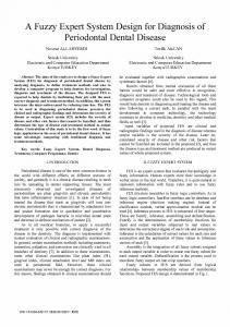
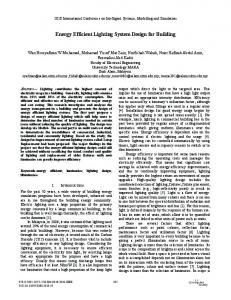
environments. A general thermal model was developed to evaluate various design options to ensure the material selected from reliability performance testing met thermal requirements. This thermal evaluation included the previous design (with seal pad) along with the design options investigated for this program [16]. The thermal resistances of the individual materials used in the test combinations were computed from the published material properties. These values are plotted in Fig. 3 to indicate the degree to which each material affects the thermal performance of the combinations. The chart shows that the metal backplanes are excellent thermal conductors as would be imagined since they are used as the primary heat sink. The thermal resistances of the attachment adhesives have a rather wide range which will impact the thermal resistance of the test combination [9]. The combinations of substrates, adhesives, and metal backplanes have an overall thermal resistance that is based upon the resistances of the individual composition layers. Because each of these layers is assumed to have the same surface area and a uniform thickness, the overall thermal resistance of the material combination can be easily computed. Using a 1-D model estimation based on Fourier’s law, a calculation of theoretical temperature losses were calculated for an estimated eight watt power input (Fig. 4 and Table III). This value was based on DCX’s maximum power input requirements for the module design. To meet the overall thermal management for this design, the overall thermal loss for this test cannot exceed 3.5 C. The modeling and testing of thermal performance was important to ensure any selected attachment options met the worse case requirements for the product design. The first notable aspect of the values generated is the excellent thermal performance of the heat sink pad. The material used in this pad had a thermal conductivity factor that was several times the value of any of the adhesives tested. What must be mentioned is that this value is based upon a perfect thermal coupling between the rear surface of the circuit board and the aluminum housing, an assumption far from accurate. While the portion of the PCB that is oriented over the pad has a great ability to dissi-
Fig. 4. Attachment material evaluation on aluminum. Temperature losses calculated and experimentally measured for an estimated 8 W power input.
TABLE III THEORETICAL TEMPERATURE DROP ACROSS INDICATED MATERIAL COMBINATION (8 W INPUT)
pate heat, the other areas of the board have very different properties. The measured air gap between the rear surface of the circuit board and the rear surface of the housing was found to be 0.185 in. As can be seen in the table, the indicated temperature drop for this application is more than 160 C. All other values for the test combinations ranged between 1.8 C and 3.5 C. In addition, the calculations using the seal pad design assume
EVANS et al.: SYSTEM DESIGN ISSUES FOR HARSH ENVIRONMENT ELECTRONICS
77
100% contact between the device and the metal. When an air gap is added (which is common in actual manufacturing) the temperature drop increases. For example, adding an air gap of 30% increases the temperature drop from 1.859 C to 1.921 C. V. ACTUAL PERFORMANCE–MODEL VALIDATION In order to offer some validation of the theoretical model described in the previous section, physical tests were performed to relate the thermal characteristics of the different material combinations. While many of these values are easy to measure, one that is not is the thermal power input into the board. The setup used for this experiment did not offer the capability of determining the quantity of heat lost into the atmosphere, though it could be reasonably said that this figure was static between all test combinations. The ambient air temperature inside the plastic encased testing area was measured for each combination tested, and there was less than 0.2 C range in all recorded temperatures. Since the heat source provider produced a constant source of heat and the loss into the environment was consistent, the variance of heat input ( ) into the system was assumed to be negligible for calculation purposes. To validate the thermal models, a water-based heat transfer system was used to conduct heat from the bottom of the substrate to the top. A special fixture was designed to ensure accuracy and repeatability. In addition, five thermocouples were used to ensure independent thermal measurements and uniform thermal performance of the material. Fig. 4 shows the measured thermal drops across three specific design options and their comparison with the thermal model. These values illustrate that the model reasonably estimates the thermal performance of each design option. After validation, the model was used as an initial design hurdle before the design option was tested for reliability. Only materials that were able to meet the 3.5 C thermal drop and below were allowed to proceed to the component reliability phase.
Fig. 5. SSA versus PSA on FR4/AL.
Fig. 6. PSA evaluation.
VI. RELIABILITY ANALYSIS As in previous analysis, the use of the term component failure in this section is assumed to mean failure of the solder joints that form the electrical connection between the component and the circuit board. 2512 resisters have shown from past data that they have the capability to survive well over 1000 thermal shock cycles on bare FR4 substrate. Of the components often used in automotive electronic circuit design, these components are often the least reliable components for thermal cycle reliability. In addition, the failure distributions are typically very tight and the 2512 resistor packages are easier to continuously monitor. Based on theoretical computations, it is anticipated that introducing any of the metal backplanes will cause serious degradation in the life expectancy of the solder joints associated with ceramic chip resistors. Because the 2512s are primarily composed of ceramic material, they have a CTE much lower than that of FR4. The CTE of any one of the tested metal backplanes is greater than that of FR4, so mechanical stresses from the expansion of the backplane will cause the substrate to expand at a faster rate. The increased thermal expansion results in additional stress in the solder joints of the resistors and therefore
potentially degrades the expected lifespan. The primary investigation of this research is to find a solution (or series of solutions) that will offer the needed thermal performance while meeting the reliability requirements. Ideally, the design would have the thermal performance of direct attachment to the metal while having the same reliability of components attached to laminate substrates without metal. This creates the need for the attachment material to have properties providing very good thermal conductivity while providing mechanical decoupling between the laminate and the metal. In this portion of the research program a series of thermal management materials including a silicone structural adhesive (SSA), a pressure-sensitive adhesive (PSA), and laminate PrePreg was investigated. Previous testing had shown the limited decoupling ability for PrePreg. The stress decoupling performance of the PrePreg material was so poor that it was only considered an option if a different backplane metal was chosen whose CTE more closely matched the FR4 laminate. For this reason, the PrePreg option was only tested using the Beryllium Copper (BeCu) backplane.
78
IEEE TRANSACTIONS ON COMPONENTS AND PACKAGING TECHNOLOGIES, VOL. 31, NO. 1, MARCH 2008
Fig. 7. Bonded PCB CTW measurements versus thermal cycles to 2512 solder joint failures.
The first evaluation was to compare the various board attachment materials using aluminum with the reliability of components using no metal backing. Fig. 5 shows the reliability of the 2512 chip components using the SSA and PSA to attach the FR4 to aluminum. Also shown is the reliability of the same 2512s attached to FR4 without metal backing. The data shows that the SSA attachment material was significantly worse than the PSA material. The figure also shows that the reliability of both attachment materials is less than the surface mount components with no metal backing to the laminate material. The next evaluation was to investigate the impact (and sensitivity) of attachment materials applied between the laminate and the metal and the application processes used to attach the metal to the FR4 substrate. Fig. 6 shows the reliability between a 5 mil and a 10 mil thick PSA attachment process. This figure also shows the impact of an additional surface preparation process (called a pickling) to improve adhesion. This evaluation shows that there was no significant difference in the component reliability for the selected thicknesses. Theoretically the attachment thickness has an impact on component reliability; however, this impact was negligible over the limited testing range. A. CTE Measurements Fig. 7 shows the relationship between the measured CTE of the substrate material for the test board and expected number of cycles-to-failure for a 2512 resistor. For each of the three data points, a failure distribution is indicated on the graph to show the 1% failure point. The lower solid line indicates the 1% failure trend of the resistors versus the CTE of the substrate. The upper
dotted line indicates the 50% failure versus the CTE measurement. Both lines indicate that the expected life of the component solder joints for 2512 s increases as the CTE of the substrate decreases. The broader application of this information is that it is additional evidence that the increase in CTE mismatch between the substrate and the component decreases the expected life of the component solder joint. B. Alternate Substrate Metals The next investigation was to try a different backplane metal with properties which better match the properties of the substrate material. The proposed aluminum alternative for testing was beryllium copper (BeCu). BeCu was tested knowing that it was so expensive that any design utilizing it was cost prohibitive unless money could be recovered somewhere else in the design. Thus, the only combination that could be cost effective utilized a PrePreg bonding material to affix the backplane to the PCB. This adhesive was not tested with the aluminum because the PrePreg material had such inelastic characteristics that it would buffer very little of the mechanical stresses associated with material expansion. Thus, if a material such as aluminum was used, the CTE mismatch along with the strong inelastic bond would be a very destructive combination. It was hoped that the mismatch between the BeCu and FR4 laminate material would be low, thus yielding higher component reliability. As can be seen in Fig. 8, the BeCu and PrePreg combination proved to be only slightly better than the PSA material at the 1% failure intercept. As in previous situations, this margin of improvement is so small that it could be attributed to error or
EVANS et al.: SYSTEM DESIGN ISSUES FOR HARSH ENVIRONMENT ELECTRONICS
79
TABLE IV VALUES OF ANAND CONSTANTS USED FOR SIMULATION
TABLE V MATERIAL PROPERTIES Fig. 8. Comparing the reliability of the BeCu/PrePreg combination.
variation in testing. An important point of discussion is the beta of the failure line for the beryllium copper data. The failure line is much more vertical than the lines attributed to the aluminum backed samples and thus the majority of the failures associated with the BeCu are expected to come well before those on the aluminum. One possible explanation for this is that beryllium was added to provide stiffness to the substrate. The material stiffness may have contributed these early failures as the substrate was affected by greater forces during cycling. In addition, the PrePreg provides a very rigid connection between the laminate substrate and metal. It is possible that the adhesive deterioration between the materials may degrade slower (than the PSA and SSA), thus maintaining a more rigid substrate over the entire test. The above reliability data provides an insight into the impact of adding metal to the back of laminate substrate materials for thermal performance. As shown, the selection of the attachment material and metal has a significant impact on the component reliability. It is also easy to see that the components select can play an important role in the reliability of a design. These analyses indicate that the reliability using metal-backed laminate substrates is very dependent on the product design. To this end, it is important to have tools and techniques to accurately predict the reliability of a wide number of materials, metals, and components without performing accelerated life testing on all design options. Below is a discussion of the development and implementation of finite element modeling with the validation associated with the above reliability data. VII. FINITE ELEMENT MODELING A. Material Models Linear and non-linear, elastic, plastic, creep, temperature and time dependent and time-independent material properties have been incorporated in the finite element models. It is well known that solder is above half its melting point at room temperature which is why time-dependent creep phenomena dominate solder joint fatigue. The thermal fatigue failure of electronic packages is associated with combined plastic-deformation and creep of solder joints. The Anand Viscoplasticity model,
TABLE VI MEASURED VALUES OF EFFECTIVE MATERIAL PROPERTIES
in ANSYS™, which has been used by several researchers to model the constitutive behavior of solder – has been used in this study. This constitutive law has been used by [1]–[3] and [11] in development of damage relationships. The constant values for the Anand Viscoplasticity model used in the models are shown in Table IV. Other materials, including ceramic, copper, printed circuit board (PCB), attachment and metal backing have been modeled with elastic material properties. Values of material properties are shown in Table V. An additional study is done for CTE measurement of the test boards which actually affects the reliability of the solder joint. Measurements are performed with Strain Gage Method on the test boards (as outlined in Measurements Group Technical Note TN-513). Table VI shows the measured values of effective material properties. Experimental data on CTE indicates that the addition of SSA/aluminum increases the CTE to 16.15 ppm C. The attachment-to-BeCu with PrePreg produces the lowest effective CTE of 15.18 ppm C. Attachment with 5-mil thick PSA on Aluminum produces the second lowest effective CTE (15.29 ppm C) of any metal-backed combination.
80
IEEE TRANSACTIONS ON COMPONENTS AND PACKAGING TECHNOLOGIES, VOL. 31, NO. 1, MARCH 2008
TABLE VII DAMAGE RELATIONSHIP CONSTANTS [11]
TABLE VIII CORRELATION OF MODEL PREDICTIONS WITH EXPERIMENTAL DATA
Fig. 9. Finite-element mesh in quarter-symmetry model.
B. FE Model Two-dimensional (plane stress, plane stress with thickness input, plane strain) and 3-D nonlinear finite element models have been developed for 2512 chip resistors. The 2-D models have been investigated mainly for computational efficiency. Material configurations investigated include, two types of metal substrates Aluminum and Beryllium Copper and three types of adhesives including, SSA, PSA, and PrePreg. SOLID45 elements have been used for resistor and PCB. VISCO107 elements have been used for solder. The test vehicles have been subjected to liquid-to-liquid temperature shock. The thermal shock temperature range is, 165 C ( 40 C to 125 C). The thermal shock duration is 15 minutes with 5 minutes dwells at each temperature extreme. The quarter model has a symmetry boundary condition along the symmetry line of the full package and vertical movement is free along the corner edge (centerline) of the package. A typical 3-D finite element mesh of a quarter symmetry package is shown in Fig. 9. The element thickness has been chosen to be 1.5 mils for the correlation. A volume averaging technique was used to reduce this sensitivity to meshing. For all configurations considered, the stresses elastic and plastic strains, displacements and total plastic work done by each element were calculated and then used for further calculations. The following damage relationship from [11] (see Table VII) has been used for computation of cyclic life
where , , , and are Thermomechanical Fatigue Constants, is the number of Cycles, is the crack length, and is the number of cycles to crack initiation. Model predictions agree with experimental data both in trends and in absolute values within percentage of relative error noted in Table VIII. The beryllium–copper metal-back with lowest effective CTE from effective properties measurements reported earlier in the paper, also showed the lowest degradation with regard to nonmetal backed configuration.
Fig. 10. Transformer reliability.
C. Transformer Solder-Joint Reliability Transformers are often one of the least reliable components for powertrain electronics. While it is expected that the CTE better matches the metal, and thus should be more reliable on metal back substrates, this test vehicle compared the reliability of transformers on FR4 with and without metal backing. Two types of surface mount transformers were included in the test vehicle design. It can be seen below in Fig. 10 that the expected lifespan of the solder joints associated with one of the transformers are approximately double their lifespan on bare FR4. The other transformer design had no failures at the time the thermal shock test was stopped. The increase in transformer lifespan noticed with the addition of a metal backing is a function of the CTE of the metal backings. The CTE of a 2512 resistor is in the range of 3–5 ppm C, while the CTE of a transformer is in the range of 19 to 21 ppm C. The significant difference in these coefficients is found because the resistors are composed of ceramic and the transformers have a high metal content due to their internal windings. The CTE of FR4 and aluminum are 16 ppm C and 21 ppm C, respectively. The theory is that the metal backing adhered to the FR4 forces the substrate to expand and contract at a rate closer to the natural CTE of the transformer. Because this rate of expansion is closer to that of the component, solder joint stresses are minimized and therefore the life of the component is extended.
EVANS et al.: SYSTEM DESIGN ISSUES FOR HARSH ENVIRONMENT ELECTRONICS
81
Fig. 11. 2512 Lead encapsulation with epoxy.
Fig. 13. Silicone based encapsulate.
Fig. 12. Component reliability with solder joint encapsulation.
D. Reliability With Encapsulates and Conformal Coatings One possible option to improve component level reliability is the use of encapsulates or conformal coats for the module. This solution is intended to absorb some of the thermal stresses and physically hold the component in place delaying the crack initiation and delaying the solder joint separation after the crack has occurred. There are many methods for coating these components from individually coating the component termination to completely covering the entire circuit board assembly. Obviously each of these options has material cost and manufacturing process ramifications and the particular selection will be based on many factors. The first option investigated was the use of epoxy encapsulants coating the individual component termination (Fig. 11). This option is expected to provide the greatest improvement in component reliability but is the most expensive to process for a large number of components.Fig.12showsthereliabilityimprovement for one printed board attachment material. Notice that the component reliability improved significant an actually exceeds the reliability of the 2512 component on FR4 without metal backing. For a design where the usage of large chip components is very low or the manufacturing volumes are low, this solution may provide an outstanding solution to solve the component reliability problem. However, since many designs involve many large chip components and since automotive applications typically involve high volume and low cost, other solutions were explored. Three basic types of additional encapsulation materials were evaluated for the enhancement of design life. These types
were silicone based polymers, epoxies, and one silicone/epoxy copolymer adhesive. Theoretically, the lower tensile strengths and low glass transition temperatures of silicone materials make them excellent candidates for conformal coat application. The benefits of these material properties in a conformal coat application are both the uniform bond that is formed across the surface of the PCB, and the fact that this bond has elastic characteristics which will not destroy components due to expansion and contraction. Epoxies generally have higher tensile strengths and offer a more rigid bond between the bonding surfaces. This is important because high-strength epoxies are more capable of isolating stresses from the solder joints than many of the encapsulants containing silicone. The downside to these epoxy materials is that they cannot be applied as a conformal coat due to their high strength. Instead of expanding and contracting with the FR4 material of the circuit board, the epoxy actually controls the expansion rate of the PCB. The strength of the epoxy bond works against the adhesive attaching the backplane to the PCB, and in the case of one test, the PCB was peeled from its backplane. Many of the encapsulation materials tested were epoxies. These material types typically have much higher tensile strengths, on the order of 1000 that of the silicone-based materials. Bonds created by the epoxy materials are much more rigid and have the capability of improving solder joint reliability. However, because this bond is more rigid, the material is less suitable for uniform application across a non-uniform surface. Since it was decided that these epoxies could not be applied to individual component leads in a full-scale production scenario, individual component encapsulation was evaluated. Component encapsulation allows for imprecise rapid dispensing of material without covering the entire surface of the circuit board. The idea is to achieve the reliability benefits of individual solder joint encapsulation without devoting the cycle time necessary for precision material application. Figs. 13 and 14 show application of the encapsulation materials to the groups of resistors on the test vehicles.
82
IEEE TRANSACTIONS ON COMPONENTS AND PACKAGING TECHNOLOGIES, VOL. 31, NO. 1, MARCH 2008
Fig. 16. Conformal coating application. Fig. 14. Non-silicone based encapsulate.
Fig. 17. Cracked conformal coating (15
2).
Fig. 15. Effect of selective encapsulations on reliability.
Encapsulation materials evaluated for selective component application were a combination of silicone based and non-silicone based materials. These materials were dispensed over each of the resistor banks on the test vehicle in hopes of minimizing solder joint stresses. From the data in Fig. 15, it can be seen that the effect of the selective coatings was highly variable. This investigation illustrates that many selective coats can provide a significant reliability improvement and some can approach the reliability of the 2512 components on FR4 without metal backing. This data also illustrates the actual improvement is somewhat process dependent and accounts for most of the Weibull correlation ( ) discrepancies shown on this figure. To improve the consistency of the reliability data and to match the manufacturing process of many high volume manufacturers, a final series of encapsulants were investigated. This series completely coated the circuit board (SSA conformal coats) and is intended to provide the reliability improvement and circuit protection often desired for under-the-hood automotive electronics.
The SSA conformal coating application of an encapsulation material is shown in Fig. 16. The material is applied using a spray nozzle, which coats the entire top surface of the circuit board, providing rapid application of the encapsulation material. The thickness of the application is less than the selective encapsulations and the viscosity of the coating is generally less viscous. It is apparent that the SSA conformal coatings are undertaking stresses at the resistor joints by looking at the image shown in Fig. 17. This image was taken at 15 magnification with an SEM and shows cracking in the coating over the resistor after undergoing 2000 cycles. The materials used as conformal coatings generally had less tensile strength than the spot epoxies for reasons previously described. Possibly these lower tensile strengths caused the coating to crack at the points of maximum stress. Fig. 18 shows the thermal shock failure cycle relationship between each of the tested materials applied as a conformal coating. The above figure shows the improvement in failure consistency over the selective coating operations. This figure also illustrates that the material used for conformal coating can have
EVANS et al.: SYSTEM DESIGN ISSUES FOR HARSH ENVIRONMENT ELECTRONICS
83
Fig. 20. Cross section of component with encapsulant.
Fig. 18. Reliability relationship between SSA conformal coating materials for 2512 chip resistors. Fig. 21. Thermal image of test circuit.
Fig. 19. Cross section of a tested 2512 chip resistor component.
a significant impact on the improvements in component reliability. This selection is somewhat design dependent and must conform to the cost and manufacturing process requirements for the particular design. E. Failure Analysis The above investigation addressed the component reliability and thermal performance of using a variety of attachment materials and encapsulates. One additional investigation needed to complete this study is the failure analysis of the failed components and the continued thermal performance (potential delamination) of the substrate. For solder joint failures, a number of cross sections were investigated to ensure proper wetting of the solder and that no problems were caused by the component termination of substrate pad. Fig. 19 shows the typical cross section of the tested components. All components tested exhibited similar failure criteria. During all analysis, only standard solder joint fatigue failures were shown and the investigators feel all data presented are valid. The failure analysis changes slightly for components which have been encapsulated. Fig. 20 shows a chip component with encapsulant. Notice that the crack initiation is much lower to the circuit board and does not completely separate. This is very
common with previously encapsulations tested at CAVE and illustrates the reasons the solder joint life is extended with encapsulations and conformal coatings. The final investigation for failure analysis is the question of continued thermal performance of the substrate throughout the product life. To investigate this, many samples were tested before and after thermal cycling for continued thermal performance. The method of locating delaminations involves thermally testing the sample before and after accelerated life testing. The image from the initial testing is directly compared to the image created after thermal shock testing. A comparison image is created by the WinTES software indicating temperature differences between the two images. If the majority of the points on the images compared are very similar, then conclusions can be drawn about areas on the board showing significant temperature differences before and after thermal shock testing. Since the thermal performance is time dependent, these images were 0 until the assembly reached a steady-state taken from time value (approximately 2 min). Fig. 21 shows the thermal image of a test circuit that had not been thermal cycled while Fig. 22 shows the thermal image from a test assembly after thermal cycling. Notice that there are some minor areas of thermal change, which indicates that the thermal performance has deteriorated slightly. For all the data shown, this thermal change is believed to be very minor and does not constitute a series failure. CAVE tested many materials where the boards completely separated (data not shown). For all assemblies tested, if the circuit assembly did not demonstrate circuit board to metal separation during the cycle range, the thermal performance did not deteriorate significantly. VIII. SUMMARY In this paper, various configurations of printed-circuit substrates have been investigated for competing design goals of solder-joint reliability and thermal performance. Various parts including 2512 chip resistors, and surface mount transformers have been studied for thermomechanical reliability on
84
IEEE TRANSACTIONS ON COMPONENTS AND PACKAGING TECHNOLOGIES, VOL. 31, NO. 1, MARCH 2008
needed for these same product designs to meet higher temperature environments. Because of these issues facing the harsh environments industry, CAVE is actively addressing these issues for next generation applications. REFERENCES
Fig. 22. Thermal image of test circuit after thermal cycling.
metal-backed PCBs. Board configurations studied include, aluminum, and beryllium-copper in presence of various adhesives including Pre-Preg, Pressure Sensitive Adhesives, and Silicone Structural Adhesive. It has been shown that the addition of an aluminum plate, adhesively attached to organic laminate PCB increases the CTE of the Laminate Assembly. The effect of the increased CTE on decrease in reliability has been demonstrated on metal-backed board assemblies subjected to thermal shock tests from 40 C to 125 C. Organic laminate assemblies attached with pressure-sensitive adhesive/Aluminum and Pre-Preg/BeCu have been shown to exhibit best thermomechanical reliability for all the configurations tested.
IX. CONCLUSION The research described herein provides a framework for understanding the issues and material selection criteria for using metal adhered to FR4 substrates for harsh environment applications. It has been shown that, the attachment material selected and encapsulation material both play a critical role in meeting the reliability goals for harsh environments. The addition of metal backing increases the CTE of the substrate and create potential reliability issues for many electronic packages. While the metal improves the effective thermal conductivity and offers a systems level cost savings for many designs, it will reduce the overall reliability for low CTE packages. This reduction is in direct contrast to the evolution of new packaging technologies, the increase in operating temperatures for the vehicle (i.e., 150 C and above) , and the increased reliability requirements ( 150 000 miles) facing automotive suppliers. While this research focused on the thermal performance and reliability impact of board attachment materials and the use of encapsulants and coatings, further investigations are needed to evaluate the broader impact on all electronic devices. Many of these devices will have similar reliability concerns and will not be helped by encapsulants. For example, small ball grid array packages will have reduced reliability when attached to metal. Underfill materials will be needed to increase the reliability of these packages. In addition, many leadless packages may have difficulty in meeting automotive requirements when attached to metal backed substrates. Finally, alternative materials may be
[1] R. Darveaux, “Solder joint fatigue life model,” in Proc. TMS’97 Conf., 1997, pp. 213–218. [2] R. Darveaux and K. Banerji, “Constitutive relations for tin-based solder joints,” IEEE Trans. Compon., Hybrids, Manufact. Technol., vol. 15, no. 6, pp. 1013–1024, Dec. 1992. [3] R. Darveaux, K. Banerji, A. Mawer, and G. Dody, “Reliability of plastic ball grid array assembly,” in Ball Grid Array Technology, J. Lau, Ed. New York: McGraw-Hill, 1995, pp. 379–442. [4] J. L. Evans, W. Johnson, J. Suhling, R. Thompson, and P. Seto, “Reliability of next generation components and substrates for under-the-hood automotive electronics,” in Proc. SMTA Int., Chicago, IL, 2002, pp. 1–7. [5] “World OEM automotive electronics to 2005,” in Market Study. Cleveland, OH: Freedonia Group, 2001. [6] Harper and A. Charles, Eds., Electronic Packaging and Interconnection Handbook. New York: McGraw-Hill, 1991, pp. 2.34–2.36. [7] J. R. Wayne, J. L. Evans, P. Jacobsen, and J. R. Thompson, “High temperature automotive electronics,” IEEE Trans. Electron. Packag. Manufact., vol. 27, no. 2, pp. 164–176, Jul. 2004. [8] J. R. Wayne, J. L. Evans, L. E. Bosley, and C. S. Romanczuk, “High temperature requirements for automotive electronic controllers,” in Proc. 2nd Int. High Temp. Electron. Conf., Jun. 1994, pp. I-3–I-7. [9] S. Kakac and Y. Yener, Heat Conduction, 3rd ed. Washington, D.C.: Taylor & Francis, 1992. [10] G. Kobe, “Electronic what’s the driving the growth electronics in motor vehicles,” Automotive Industries, vol. 180, no. 8, pp. 26–33, Aug. 2000. [11] P. Lall, N. Islam, J. Suhling, and R. Darveaux, “Model for BGA and CSP in automotive underhood environments,” IEEE Trans. Compon., Packag., Manufact. Technol. A, vol. 27, no. 3, pp. 585–593, Sep. 2004. [12] Prasad and P. Ray, Surface Mount Technology—Principals and Practice. New York: Chapman & Hall, 1997, pp. 149–150. [13] C. S. Romanczuk, S. W. Burcham, J. L. Evans, R. W. Knight, and R. W. Johnson, “Finite element analysis of the thermal characteristics of an automotive powertrain controller,” in Proc. ISHM Int. Symp. Hybrid Microelectron., Nov. 1993, pp. 650–655. [14] P. Roubaud, S. Prasad, F. Carson, R. Bulwith, R. Herber, S. Kamath, and A. Garcia, “Impact of intermetallic growth on the mechanical strength of Pb-free BGA assemblies,” in Proc. APEX’01 Conf., 2001, pp. 1–5. [15] J. C. Suhling, J. L. Evans, S. T. Lin, R. W. Johnson, and B. Han, “Finite element and moire interferometry study of chip capacitor reliability,” in Proc. InterPACK’97, Jun. 1997, pp. 15–19. [16] J. C. Suhling, R. W. Johnson, J. D. White, K. W. Matthai, R. W. Knight, C. S. Romanczuk, and S. W. Burcham, “Solder joint reliability of surface mount chip resistors/capacitors on insulated metal substrates,” in Proc. Electron. Compon. Technol. Conf., 1994, pp. 465–473.
John L. Evans received the B.S. and M.S. degrees in electrical engineering from Auburn University, Auburn, AL, and the Ph.D. degree in engineering management and manufacturing systems engineering from the University of Alabama, Huntsville. He is an Associate Professor of Industrial and Systems Engineering and Associate Director of the National Science Foundation Center for Advanced Vehicle Electronics (CAVE), Auburn University. Before joining Auburn University in 2001, he spent 17 years at Daimler Chrysler Corporation in Huntsville. During his tenure at DaimlerChrysler, he was a Design Engineer, Lead Engineer, Financial Specialist, Electronics Packaging Supervisor, and Technology Manager. His most recent position was Manager of strategic business and advanced technology for DaimlerChrysler Hunstville, Electronics. He also served as an Adjunct Assistant Professor (1991–2001) in the Department of Industrial and Systems Engineering and as a Lecturer in the Administrative Science Department, University of Alabama.
EVANS et al.: SYSTEM DESIGN ISSUES FOR HARSH ENVIRONMENT ELECTRONICS
Pradeep Lall (M’92) received the B.E. degree in mechanical engineering from the Delhi College of Engineering, University of Delhi, Delhi, India, in 1988, the M.S. and Ph.D. degrees in mechanical engineering from the University of Maryland, College Park, in 1989 and 1993, respectively, and the M.B.A. degree from Kellogg School of Management, Northwestern University, Evanston, IL, in 2002. He has ten years of industry experience. He was previously with Motorola’s Wireless Technology Center. He is currently an Associate Professor with the Department of Mechanical Engineering and Associate Director of the NSF Center for Advanced Vehicle Electronics, Auburn University, Auburn, AL. He has published extensively in the area of electronic packaging with emphasis on modeling and predictive techniques. He has authored and coauthored several book chapters and is an Associate Editor for the ASME Journal of Electronic Packaging. He is lead author of Influence of Temperature on Microelectronic and System Reliability (Boca Raton, FL: CRC, 1997). He holds three U.S. patents. Dr. Lall received the Samuel Ginn College of Engineering Senior Faculty Research Award in 2007, three Motorola Outstanding Innovation awards, five Motorola Engineering Awards, four Publication Awards, and nine Best Paper Awards. He is a Six-Sigma Black-Belt in Statistics, an Associate Editor for the IEEE TRANSACTIONS ON ELECTRONICS PACKAGING MANUFACTURING, and a Member of Beta Gamma Sigma.
Roy Knight received the Ph.D. degree from The University of Texas, Austin, in 1986. He is a faculty member with the Mechanical Engineering Department, Auburn University, Auburn, AL. He teaches thermal science courses, works on thermal issues in electronics packaging, and is a Researcher with the Center for Advanced Vehicle Electronics (CAVE).
85
Elliott Crain received the B.S. degree in industrial and systems engineering and the M.S. degree in electronics manufacturing from Auburn University, Auburn, AL, in 2001 and 2003, respectively. He has spent the last five years in supply chain engineering, three years with Exel Logistics and currently as a Logistics Manager at The Home Depot, Atlanta, GA.
Tushar Shete received the B.E degree in mechanical engineering from the University of Pune, Pune, India, and the M.S. degree in mechanical engineering from Auburn University, Auburn, AL, in 2004. He is currently a Reliability Engineer at Tyco Electronics Power Systems, Mesquite, TX. Prior to that, he was Research Assistant in Department of Mechanical Engineering, Auburn University, working in the field of electronic packaging reliability under harsh thermomechanical environments, with emphasis on modeling and experimental techniques.
James R. Thompson received the B.S. degree in chemical engineering and the M.S. degree in mechanical and aerospace engineering from The University of Alabama, Huntsville. He is presently employed by Continental Corporation, Huntsville, where he is a Business Development Manager for the Americas. His previous experience includes Advance Engineering Manager with Chrysler and DaimlerChrysler Corporations where he was responsible for advance product, materials, and process development. He was also a Research and Development Manager with Thiokol Corporation where he was responsible for material characterization, and shelf-life extension programs for satellite launch and tactical missile systems. In addition, he was a member of the Space Shuttle Solid Rocket Booster (SRB) redesign team where he was responsible for the characterization and viscoelastic modeling of the SRB solid propellant.