CHEN LAYOUT
6/20/11
4:11 PM
Page 148
ACCEPTED FROM OPEN CALL
System-Level Simulation Methodology and Platform for Mobile Cellular Systems Li Chen, Wenwen Chen, Bin Wang, Xin Zhang, Hongyang Chen, and Dacheng Yang
ABSTRACT System-level simulation has been widely used to evaluate the comprehensive performance of different mobile cellular systems. System-level simulation methodologies for different systems have been discussed by different organizations and institutions. However, the framework for a unified simulation methodology and platform has not been established. In this article, we propose a general unified simulation methodology for different cellular systems. Both the design of the simulation structure and the establishment of the simulation platform are studied. Meanwhile, the unified modeling and the realization of various modules related to the system-level simulation are presented. The proposed unified simulation methodology and the general simulation platform can be used to evaluate the performance of multiple mobile communication systems fairly. Finally, the overall performance of LTE and Mobile WiMAX systems is evaluated through the proposed framework. The key simulation results for both Full Buffer and VoIP traffics are presented and discussed. It is shown that the LTE system exhibits better performance than Mobile WiMAX.
INTRODUCTION Mobile communication has continued to evolve rapidly in recent years. The third-generation (3G) mobile cellular systems, such as wideband code division multiple access (WCDMA), cdma2000, time division synchronous code division multiple access (TD-SCDMA), and world interoperability for microwave access (WiMAX), have been commercialized, while the research for the new beyond 3G (B3G) systems (e.g., the Third Generation Partnership Project (3GPP) long term evolution (LTE) and 802.16m) or even 4G systems (e.g., LTE-Advanced (LTE-A)) are still in progress. Many commercial mobile systems today, which are based on orthogonal frequency division multiple access (OFDMA) technology with relatively wide bands, evolved from International Mobile Telecommunications-2000 (IMT-2000). In order to evaluate the expected performance of these mobile cellular systems or to do research on related key technologies of air interface, we
148
0163-6804/11/$25.00 © 2011 IEEE
often have to resort to the system-level simulation. Due to the importance of system-level simulation, multiple simulation methodologies have been proposed by 3GPP, 3GPP2, and the Institute of Electrical and Electronics Engineers (IEEE). Each organization has published the corresponding simulation methodology for the system it standardizes. For example, 3GPP2 provided the simulation methodology for cdma2000 1x evolution-data optimized (EV-DO)/evolution-data and voice (EV-DV) evaluations [1], IEEE announced [2, 3] for 802.16 series standards, and 3GPP issued [4, 5] for WCDMA. Besides, numerous related papers have been published in IEEE. These methodologies evolve with the standardization progress. Each of them, however, focuses only on one specific system. One may ask a natural question: can we evaluate the performance of multiple mobile cellular systems through system-level simulation in a unified framework? Actually, this problem has not been studied extensively. In [6], Gao et al. has proposed a fair manner to evaluate different systems. However, they only unified the simulation configurations to compare the performance of different systems fairly. There are still some issues that need to be clarified regarding the design and realization of a system-level simulation platform and the unified simulation methodology. Also, several other problems about the system-level simulation e.g., how to model the modules and interfaces, how to evaluate the key technologies involved, and the network performance, etc., have not been fully considered yet. All of these obstacles constitute the motivations for our work in this article. Our major task in this article is to establish a unified framework for system-level simulation methodologies for different mobile cellular systems. In addition to capturing important aspects of the unified simulation methodology, this article also highlights the modules in the framework for system-level simulation. Moreover, the issues among different simulation methodologies developed by various standardization bodies are clarified. Finally, we show an example evaluating the performance of LTE and Mobile WiMAX systems using the unified system-level simulation methodology. The analytical and simulation
IEEE Communications Magazine • July 2011
CHEN LAYOUT
6/20/11
4:11 PM
Page 149
work provides much insight into the technical principle and also the benefits of a deep understanding of the potential of commercial mobile communication systems. The rest of this article is organized as follows. The next section gives an overview of systemlevel simulation. We study the unified modeling of various simulation modules. After that, the unified system-level simulation evaluation methodology and platform are proposed. We present simulation results by using the proposed methodology and platform. Finally, conclusions are summarized.
Resource management Application layer System-level simulation
MAC layer parameter Traffic model
TCP/IP layer
Transport layer
Interface
MAC layer
OVERVIEW OF SYSTEM-LEVEL SIMULATION PURPOSE OF SIMULATION Due to the complicated structures of mobile cellular communication systems, we cannot describe them completely through a simple and abstracted mathematical model. Thus, we always resort to the simulation to evaluate their performance. Computer programs are used to simulate the operating mechanisms of mobile cellular communication systems, the loaded traffics, etc. The performance of these systems can be reflected by the results obtained from the simulation programs ultimately. Moreover, the simulation can be used as an assistant tool for theoretical studies. Whenever new algorithms or strategies are proposed, we usually cannot apply them directly to real networks to evaluate their performance because of the high cost. Since the simulation is able to emulate the practical scenarios in a statistical manner, qualitative or quantitative complexity analysis and performance evaluation of any new algorithm or strategy can rely on the simulation. In the following, we discuss the advantages of the simulation, including its efficiency and flexibility, which are also the reasons why we need the simulation. The efficiency means that we can develop a simulation platform for a mobile communication system in a very short period of time instead of constructing a practical complicated system. By the use of the simulation platform, the system performance can be predicted easily and effectively. The flexibility refers to facilely changing any component of the system by modifying the corresponding programming module with low cost and risk. Valid conclusions and suggestions can be obtained from the simulation. However, they are not obsoletely accurate since it is impossible for the simulation to describe the physical nature of the actual system with infinite precision. The simulations do not have complete authenticity, reliability, or reproducibility, but they have quasi-authenticity, quasi-reliability, and quasireproducibility. They only approach the physical nature in the sense of probability.
LINK-LEVEL SIMULATION VS. SYSTEM-LEVEL SIMULATION The simulation for mobile communication systems includes the link-level simulation and the system-level simulation. Both of them are widely
IEEE Communications Magazine • July 2011
Physical layer parameter Physical layer
Link-level simulation
Propagation model Channel model
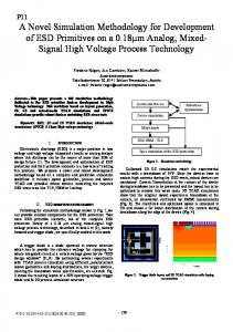
Figure 1. Component layers and model for simulation methodology. employed to evaluate the associated performance. The link-level simulation focuses on the performance of a transmission between base stations (BSs) and mobile stations (MSs). The performance metrics usually include the bit error rate (BER), signal to noise ratio (SNR), achievable rate, etc. In general, the link-level simulation concentrates on the physical layer. On the left side of Fig.1, we show its relationship to other components in communications. For the purpose of theoretical studies, the performance of modulation/demodulation or coding/decoding schemes in different radio channel models can be obtained from the link-level simulation. The scenario for the system-level simulation generally consists of a network with multiple BSs and MSs. Different from the link-level simulation, the system-level simulation focuses on the application layer performance metrics as expressed by system throughput, user fairness, user-perceived quality of service (QoS), handover delay or success rate, etc. The system-level simulation concentrates on the higher layers above the physical layer, such as the MAC layer, transport layer, TCP/IP layer, and application layer. Figure 1 shows the component layers related to the system-level simulation. For the purpose of theoretical studies, the performance of resource allocation, handover, cell deployment, or other strategies can be obtained from the system-level simulation.
STRUCTURE OF SYSTEM-LEVEL SIMULATION The simulation methodology model is plotted in Fig. 1. System-level simulation includes the scheduling process, power control process, adaptive modulation and coding scheme (MCS) selection process, and other MAC layer processes. Also, the system-level simulation needs to be operated with incorporation of the link-level simulation. In general, the link-level simulation is separately abstracted to a set of SNR-BER curves on different MCS levels. The outputs of the link-level simulation are mapped through an interface to the system-level simulation as inputs of the system-level simulation.
149
CHEN LAYOUT
6/20/11
4:11 PM
Simulation methodologies have been comprehensively discussed in different organizations and institutions. With the evolution of communication standardization, international organizations and companies have made much effort to develop the simulation methodologies for them and their evolutions.
Page 150
How can we know the precision of this system-level simulation methodology? How can we know whether the proposed platform for the system-level simulation is comparable to other works? In order to guarantee the precision and comparability, we developed the following mechanism. First, we establish the platform for the system-level simulation of a certain cellular system, and then the platform needs to be calibrated with the corresponding standard organizations, such as the simulation methodologies from the International Telecommunication Union Recommendations (ITU-R), 3GPP, 3GPP2, and IEEE WiMAX forum. The calibration method is to adapt the simulation platform to the achievement of the same simulation results as that from the standard organizations with the same parameters and conditions. After the common calibration, we can confirm that the simulation platform is accurate enough to implement the performance evaluation or compare with others.
OVERVIEW OF EXISTING SIMULATION METHODOLOGIES Simulation methodologies have been comprehensively discussed in different organizations and institutions. With the evolution of communication standardization, international organizations and companies have made much effort to develop the simulation methodologies for them and their evolutions. The simulation methodologies for cdma2000 and Mobile WiMAX systems have been explicitly presented in 3GPP2 C.R1002 [1] and WiMAX forum document [3], respectively. 3GPP has also made an effort on simulation methodology for WCDMA and its evolutions such as HSDPA/HSUPA and LTE. However, the methodology for LTE-A has not been established yet. It would be improved with the development of the LTE-A standard. These simulation methodologies involve many modules, including the cell layout model, channel model, radio resource allocation, interference model, physical layer abstraction, traffic models, and other key factors. In the next section, we will study the unified modeling of these modules in detail and discuss their realization or deployment in the system-level simulation.
UNIFIED MODELING OF SIMULATION MODULES Through the overview of existing methodologies, we find that different simulation methodologies and configurations proposed by various organizations aim at different systems, and they are not applicable to each other. Thus, we propose a unified structure for a simulation model and simulation platform, and establish a general framework for different system-level simulation methodologies in this article. The models proposed here provide a unified method to evaluate the performance of various systems. It eliminates many inconsistent aspects in previous literature and keeps the most essential parts. There are many static and dynamic modules for the system-level simulation. In this section,
150
we study the unified models of various modules, which are the components of the unified systemlevel simulation methodology. Their simulation methods and realization in the platform are also discussed.
CELL LAYOUT MODEL AND WRAPAROUND TECHNOLOGY There are several common service area models: single-cell, 7-cell, 19-cell, and 36-cell. If the number of cells in the model is too large, which means the system has many BSs and MSs, it will take a long time to develop and debug the simulation platform. The reason is that the calibration of the simulation platform needs iteratively modifying, running the platform, and analyzing results. Thus, the model with fewer cells can accelerate the evolution of the simulation platform. However, if the number of cells in the model is too small, the inter-cell interference (ICI) suffered by one cell may not be enough. Thus, it may not be able to reflect the practice with tolerable precision. Therefore, the scalability and the adaptability of the simulation platform need to be considered in the selection of the service area model. In some methodologies, the 19cell model is the preferred standard service area. WrapAround is a technology that can simulate the ICI and at the same time improve simulation efficiency. In the 19-cell model without WrapAround, a serious defect would happen in the ICI calculation for the MSs in the edge cells. After the simulation, only the data of the center cell that are reliable can be collected, which leads to low efficiency. Much more time is consumed by the work of the MSs that are out of the center cell, but they only serve as foils to a small quantity of MSs in the center cell. Thus, WrapAround is recommended as the cell layout of the simulation platform to form a toroidal surface to enable faster simulation run times. A toroidal surface is chosen because it can be easily formed from a rhombus by joining the opposing edges. The cell cluster of 19-cell is virtually repeated 8 times at rhombus lattice vertices. Then the structure includes the original 19-cell cluster remaining in the center, called the center cell cluster, while the eight copies evenly surround this center set. By adopting WrapAround technology, the simulation platform can solve the ICI calculation problem since each cell of the center cluster has enough interference. Also, it is able to improve the efficiency of the simulation and the data statistics since all the data in the center cell cluster can be collected. It only makes the system realization a little more complicated. Typically, the MSs are uniformly distributed in the system. Some methodologies [3, 7] specify that every cell or sector has the same number of MSs. This is because with the same number of MSs, not only the traffic density is guaranteed to be uniform in the simulation, but also the effects of the admission control could not be taken into account specially. In order to satisfy the requirements of debugging, testing and researching, the simulation platform should support some fashions of MS dropping. These may include fixed point dropping with only one MS in the service
IEEE Communications Magazine • July 2011
CHEN LAYOUT
6/20/11
4:11 PM
Page 151
area or fixed point dropping with one MS each sector, which can ensure the fast debugging of the platform; fixed point dropping with multiple MSs in each sector, which is beneficial to the fast comparison testing; hotspot dropping, which can support the research for the hotspot, admission control and congestion control; or dropping with fixed cell radius. It proposes the requirements for the design of the simulation system that the operations of users and the realization of dropping algorithm should be detached.
CHANNEL MODEL The multipath channel model proposed in ITU-R M.1225 [7] has been widely used for the cellular systems with a single-input multiple-output (SIMO) (typically 1 transmit by 2 receive antennas) antenna configuration. M.1225 defines several scenarios: indoor A/B, pedestrian A/B, and vehicular A/B, each with six subpathes except for pedestrian A, which has four subpathes. The relative delay profile and average power for each subpath are also specified. Different systems have distinct bandwidths, which leads to different multipath resolutions, and we cannot use these models directly. Thus, channel models need to be modified for different systems. If multiple-input multiple-output (MIMO) technology is adopted, the spatial-time channel model (SCM) or SCM-Enhancement (SCM-E) [8] should be used to generate multipath fading. Indeed, SCM-E can also be used in SIMO with suitable setting. The simulation platforms for different systems adopt different channel models, which are recommended in corresponding simulation methodologies. For the purpose of the performance comparison among several systems, the unified mixed channel model should be applied. In [6], the authors describe how to unify the model parameters for ITU channels. They established the unified channel model by finding the similarity of number of paths, the power and the delay profile of each path, among different channel models.
RESOURCE ALLOCATION STRATEGY Resource allocation, including subcarrier assignment among users and power allocation on subcarriers, is an important issue in OFDM-based mobile cellular systems. In general, the resource allocation process can be divided into several steps: determination of the available resource; calculation of the packet transmission order over the air interface; implementation of the resource allocation signaling process; and generation of downlink (DL) or uplink (UL) MAC packets. Typical optimization problems of interest for resource allocation include the capacity problem, i.e., maximizing the sum data rate subjects to a power constraint, or the power control problem, i.e., minimizing the transmit power so that a certain quality of service metric for each user is satisfied. Besides, in order to balance the system efficiency and user fairness, we can also try to maximize the aggregate utility of users in the network. More strategies on this issue for OFDM systems are studied in [9] and its references. A basic resource unit is the minimum unit allocated to one user, and is unique for each sys-
IEEE Communications Magazine • July 2011
tem. In our simulation platform, a basic resource unit in the time-frequency domain is one subchannel in Mobile WiMAX or one resource block (RB) in LTE. On each resource unit, the proportional fair (PF), round robin scheduling algorithm, or other scheduling strategies are used for subcarrier assignment.
INTERFERENCE MODEL Interference is a primary factor that significantly affects system performance in multiuser networks, especially in OFDM systems. One of the key benefits of the OFDMA air interface is its ability to enable frequency reuse, that is, the same frequency can be used in all neighboring cells and sectors. It makes the system deployment much easier since frequency planning is no longer needed. With high frequency reuse patterns, however, the system becomes interference limited. The ICI seen by an MS in DL or a BS in UL is typically frequency- and time-selective. In the system-level simulation, the ICI should be modeled according to the practical channel model, including large scale fading and fast fading components. In our simulation platform, the interference is computed in real-time along with the simulation running through the signals received by the MS from different BSs or by the BS from different MSs.
Interference is a primary factor that significantly affects system performance in multiuser networks, especially in OFDM systems. One of the key benefits of the OFDMA air interface is its ability to enable frequency reuse, that is, the same frequency can be used in all neighboring cells and sectors.
PHYSICAL LAYER ABSTRACTION In general, in order to reduce the complexity of the simulation platform, the effects of the linklevel strategies are abstracted to a set of curves, which are the inputs of the system-level simulation as described previously. In OFDM systems, the total bandwidth is divided into a number of orthogonal subcarriers, each of which has a signal to interference plus noise ratio (SINR). Several subcarriers are combined into a subchannel, and its effective SINR is the combination of the SINRs of these subcarriers. Many mapping solutions have been proposed. The 3GPP and the WiMAX Forum AWG group recommend the exponential effective SINR mapping (EESM) model as a typical and default solution for the SINR combination. When the bandwidth is large, such as 10MHz in Mobile WiMAX or LTE systems, the size of fast Fourier transform (FFT) is 1024. The amount of calculation for the SINRs on subcarriers or RBs becomes quite large, which would greatly reduce simulation efficiency. Thus, we propose an interpolation method, which calculates the SINR every four or eight subcarriers first, and then the SINRs on all subcarriers can be obtained through linear interpolation. Through our simulation verification and validation, it can be found that if the effective SINR is calculated by using the values on every four subcarriers instead of every subcarrier, the simulation accuracy under the conditions and models mentioned above will not be affected, but the simulation complexity will be greatly reduced.
SERVICE AND TRAFFIC MODELS With the development of mobile cellular systems, the traffics evolve from voice dominant toward mixed ones. Different types of traffics have dif-
151
CHEN LAYOUT
6/20/11
4:11 PM
Page 152
)
Slotwork()
tw or
Readtime()
k(
Slo
or
Driven object
n
rive
e-d
Tim
tw
Driven object
Forward
Slo
k()
Driving module
Driven object
Figure 2. Structure of modules. ferent performance evaluation output metrics. Although there are various types of traffics in practical systems, they can be classified into two categories. One is the packet data traffic without delay requirement, such as Full Buffer. System throughput and user fairness are two guidelines for this type of traffic. However, the throughput is associated with the system bandwidth and typically increases when more bandwidths are occupied. Thus, the spectrum efficiency, which is defined as the throughput divided by the effective bandwidth with unit of bits per second per Hertz, is the normalized performance index for this type of traffic. The other category is the delay sensitive traffic that has a delay requirement, such as voice over IP (VoIP) or streaming media. The packet delay and outage probability are the most critical performance metrics. Different traffic models generate data with different characteristics. However, all traffics can be abstracted as a data generator in the system-level simulation platform. In the platform, there is a data pool at the transmitter which contains data to be transmitted. The data generators for various traffic models fill in this pool with different rules. In practice, the mixed traffic is preferred.
OTHER KEY ALGORITHMS Other key technologies such as hybrid automatic repeat request (HARQ), adaptive modulation and coding (AMC), channel quality indication (CQI) feedback, power control, and interference over thermal (IoT, or rise over thermal, RoT) control in UL are standardized specifically in different systems or widely used. They may be adjusted for different systems according to their own characteristics.
UNIFIED SYSTEM-LEVEL SIMULATION METHODOLOGY AND PLATFORM Based on the unified modeling of various modules, we study the unified system-level simulation methodology and the general simulation plat-
152
form in the following. In order to compare the performance of different systems, the simulation settings should be unified. Since different systems operate under various parameters or configurations, each organization for one system proposes a body of simulation methodology and recommends a set of parameters. They cannot match each other completely. The unified simulation parameters and configurations can be obtained by comparing the characteristics of different systems, as discussed in [6]. For most of the parameters and configurations, we choose a set of common values from the values’ range or optional configurations of different systems. If there is no common value for some parameters or some system specific configurations, we could set them as close as possible for different systems. The system-level simulation platform developed by us is established based on the model shown in Fig. 1. By realizing all the unified modules above, we calibrate the simulation platform by comparing it with published results. After that, the platform can be used for the research or system performance comparison under the unified settings. The unified simulation methodology consists of the unified models of various modules and this unified flow for different systems. The general system-level simulation platform adopts a time-driven mode to drive the system progress, which is the combination of drop and time slot driven. A drop is a process by which all MSs are dropped in the service area in a certain manner. In our platform, the MSs are uniformly distributed in the system. A time slot is the minimum step duration for time in the simulation, which is determined by the system-level minimum control interval. In the Mobile WiMAX system, the period for the scheduling or the power control is a frame, so the time slot in the platform is 5ms, while in the LTE system, the time slot is 1ms since the control period is a subframe. The simulation duration for a drop contains many time slots, which is long enough for the system to become stable. The data for the system outcomes should be collected from the time slot when the simulated system is stable till the end of a drop. A drop can be regarded as one Monte-Carlo simulation. Thus, multiple drops should be simulated in the system-level simulation platform before average values are obtained. The flow for the system-level simulation platform is as follows. Before the time slot simulation, the initialization should be implemented first, which includes reading simulation parameters, initializing service area and BSs, dropping MSs in the system, initializing MSs and the path losses of links between MSs and BSs, etc. After that, the time-driven module drives the progress of the system, and other modules perform their own work in every time slot, which can be summarized in function slotwork(). The progress ends when the simulation time is out. Through the simulation flow, we can observe the relationship among different modules in the simulation platform, which is shown in Fig. 2. The interface between the driving modules and
IEEE Communications Magazine • July 2011
6/20/11
4:11 PM
Page 153
the driven objects is the slotwork() function. The clock in Fig. 2 is the time slot module. Only the system driving module that is the central controller can push the clock forward and reset it, while the other modules are driven objects, such as the behaviors of MSs and BSs, which can only read the time slot module. In the whole process of the system-level simulation, all the modules are operating based on the time slot module. The proposed unified system-level simulation methodology and the general simulation platform can be used to evaluate the performance of any mobile communication system or mobile broadband technology. The output performance of different systems is compared fairly and credibly through the unified simulation. In addition, the simulation platform can be used to evaluate the comprehensive performance of the proposed algorithm reflected in the system. With the development of mobile communication standards, the process and method to establish the unified simulation methodology are similar. The unified modeling and methodology can also be used in other areas, such as network planning and network optimization, for which suggestions can be provided through the systemlevel simulation. Moreover, the unified methodology can be extended to compare different network costs by adding some cost modules in the platform. It would be possible for operators to lower their capital and operating expenditures by deploying the system with better performance.
SIMULATION RESULTS In this section, by using the unified simulation methodologies and the methods for the unified parameters studied above, we evaluate the performance of LTE and Mobile WiMAX systems. In the following, the simulation configurations are presented first, and then the results are shown and analyzed. Some evaluating indicators for different traffic models are also presented in the following analysis. By comparing the system parameters and configurations in [3, 10], we summarize a set of unified configurations, as shown in Table 1. The V-MIMO in it is the abbreviation for virtual MIMO. The system performance greatly depends on deployment settings and system configurations below. In the simulation, all MSs are randomly dropped in a layout of three-tier 19 hexagonal cells with three identical sectors in each cell. The wraparound model is employed to simulate interference from neighboring cells. EESM is used to combine the SINRs on the subcarriers. Mobile WiMAX and LTE systems also have some specific key technologies. In Mobile WiMAX, synchronous HARQ with a four processes interlaced structure is adopted, and the maximum number of retransmissions is 4. The Chase Combing model is used to perform the SINR recalculation after the retransmission. Hard handover and AMC with six MCS levels are used in Mobile WiMAX. Besides, basic open-loop power control is applied in UL. How-
IEEE Communications Magazine • July 2011
1 Fairness criterion WiMAX LTE
0.9 0.8 0.7 0.6 CDF
CHEN LAYOUT
0.5 0.4 0.3 0.2 0.1 0
0
0.5
1
1.5 2 2.5 Normalized throughput
3
3.5
4
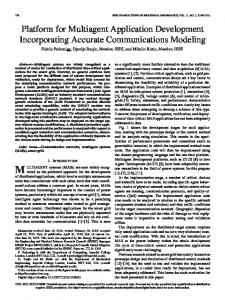
Figure 3. Fairness curves of different systems in DL and UL.
ever, in LTE, the adaptive asynchronous HARQ, Intra-LTE handover, AMC with 15 MCS levels, and closed loop power control are adopted. The simulation platform is established by Visual Studio C++. The system-level simulation is based on the unified methodology with the above configurations. The simulation results about the throughput, spectrum efficiency, user fairness for Full Buffer traffic and capacity, packet loss, and user satisfaction rate for VoIP traffic are shown hereafter. Table 2 shows the performance at the peak user rate, the system throughput, and the spectrum efficiency for Full Buffer traffic in DL and UL. It is observed that the LTE system has higher system throughput and spectrum efficiency in both DL and UL. Moreover, the cell-edge performance in LTE is also better than that in Mobile WiMAX. Another performance index for Full Buffer traffic is the fairness among users, which can be achieved by using a proper scheduling algorithm, such as PF scheduler. The throughput and the spectral efficiency discussed above refer to aggregate system performance, whereas the fairness refers to the per-user performance, especially to the performance of cell-edge users. We should make an effective tradeoff between fairness and throughput. In order to achieve satisfying fairness with high spectral efficiency at the same time, we have calibrated the relevant parameters (α-factor in PF) in scheduling algorithms so that the following two criteria are met: • Fairness curves are similar to each other in shape and under the fairness criterion, which will guarantee the consistency and fairness among different systems. • Fairness curves are as close to the fairness criterion as possible, which indicates that the spectral efficiency is maximized. Figure 3 gives the user fairness curves in DL. It is shown that all curves are on the right side
153
CHEN LAYOUT
6/20/11
4:11 PM
Page 154
Simulation Parameters
Unified Value
System Configurations Frequency
2 GHz
Bandwidth
10 MHz
Duplex
TDD
DL:UL ratio
22:15 for WiMAX; 3:2 for LTE
Antenna configuration
DL:2 × 2; UL:1 × 2(or 2 × 2V-MIMO)
BS-to-BS distance
1 km
Minimum distance between BS and MS
35 m
Maximum UL total path loss
140 dB
Frequency reuse factor
1
Thermal noise density
–174 dBm/Hz
Scheduler
PF for Full Buffer; MLWDF for VoIP
Subchannel model for Mobile WiMAX
PUSC [3]
Propagation Parameters Propagation model
COST 231 Suburban
Log-normal Shadowing Std
8.9 dB
Correlation distance of shadowing
50 m
Shadowing correlation between cells
0.5
Shadowing correlation between sectors
1.0
Channel models
SCM-E
Penetration loss
20 dB
BTS Configurations BTS transmit power
43 dBm per antenna
BTS noise figure
5 dB
BTS antenna gain with cable loss
14 dBi
Antenna height of BS
30 m
Antenna horizontal pattern
70° with 20 dB front-to-back ratio
MS Configurations MS transmit power
23 dBm
MS noise figure
8 dB
MS antenna gain
–1 dBi
Antenna height of MS
1.5 m
MS velocity
3 km/h
MS number
10/sector
Traffic type
Full Buffer and VoIP
Table 1. Simulation parameters.
154
of the three-point fairness criterion curve, guaranteeing fairness among users. At the same time, each curve is as close to the fairness criterion as possible. The two curves are close to each other, which means that they are similar in terms of fairness. In addition, the probability of users with smaller throughput in LTE is lower than that in Mobile WiMAX, which accords with the cell-edge throughput in Table 2. The fairness curves in UL similar to that in Fig. 3 are omitted. Figure 4 gives the average ICI performance of LTE and Mobile WiMAX systems with respect to the number of users per sector. It shows that LTE has lower average ICI value than Mobile WiMAX, which means LTE can mitigate the ICI more effectively. With the increase of the user number, the average ICI of users decreases for both systems. Full Buffer is an ideal data traffic without a delay requirement, which can only reflect the throughput and the spectral efficiency performance. In the following, we evaluate the performance for VoIP traffic. The voice activity factor for VoIP is 50 percent, and the total voice payload on the air interface is 40 Bytes. The results for VoIP traffic in DL and UL are listed in Table 3. VoIP capacity is the average number of users in one sector when more than 95 percent of users satisfy the following three criteria: • The packet delay for each user is not more than 50ms with probability of 98 percent. • The packet loss for each user is lower than 3 percent. • Capacities for users in DL and UL are comparable. The user satisfaction rate is the proportion of users that satisfy the packet delay and the packet loss conditions. From the results, we can see that the LTE system has higher VoIP capacity than Mobile WiMAX with a little higher packet loss proportion in DL. Besides, the user satisfaction rate of LTE is nearly equal to or higher than that of Mobile WiMAX. Thus, the LTE system has better performance than the Mobile WiMAX system in general.
CONCLUSION In this article we proposed a general unified system-level simulation evaluation methodology for mobile cellular systems and presented the framework for the establishment of a unified simulation platform. The unified methodology highlights the features of air interfaces and the advantages of different system standards. Moreover, in order to compare various systems’ performance comprehensively, the unified modeling of various modules in different systems is studied. After that, the simulation structure and the general platform are proposed. Finally, based on the unified configurations and parameter settings, simulation results of LTE and Mobile WiMAX systems for both Full Buffer and VoIP traffics in DL/UL are presented through the proposed platform. The results show that the LTE system has higher spectrum efficiency, larger VoIP capacity, and better user satisfaction than
IEEE Communications Magazine • July 2011
CHEN LAYOUT
6/20/11
4:11 PM
Page 155
Mobile WiMAX. The work in this article can serve as a reference for researchers, product developers, or engineers.
-73
LTE WiMAX
-74
REFERENCES
BIOGRAPHIES LI CHEN [S] (
[email protected]) received his B.Eng. degree in communication engineering from Beijing University of Posts and Telecommunications (BUPT) in 2007. Now he is pursuing his Ph.D. degree in communications and information systems at BUPT. His research interests focus on Network Coding, cross-layer optimization, radio resource management and performance evaluation of wireless communications. WENWEN CHEN (
[email protected]) received her B.Eng. (2007) degree in communication engineering, M.Eng. (2010) in communications and information systems from BUPT. She joined Qualcomm in 2010, as an engineer in Qualcomm Wireless Communication Technologies (China) Limited. Her research interests mainly focus on performance analysis of key technologies for B3G/4G systems. BIN WANG [S] (
[email protected]) received his B.Eng. degree in communication engineering from BUPT in 2009. Now he is pursuing his M.Eng. Degree in communications and information systems at BUPT. His research interests focus on Device to Device underlay cellular networks, cooperation communications, and performance evaluation of wireless communications. XIN ZHANG [M] (
[email protected]) received his B.Eng. (1997) degree in communication engineering, M.Eng. (2000) degree in signal and information processing, and Ph.D. (2003) degree in communications and information systems from BUPT. He joined BUPT in 2003, working in the Wireless Theories and Technologies Laboratory, and focuses his research mainly on key technologies and performance analysis of air interfaces for wireless networks. HONGYANG CHEN (
[email protected]) received his B.S. (2003) degree and M.S. (2006) degree in Institute of Mobile Communications from Southwest Jiaotong University, Chengdu, China. Currently, he is a Ph.D. student of the Graduate School of Information Science and Technology, University of Tokyo. In 2009, he was a visiting researcher in the UCLA Adaptive Systems Laboratory, under the supervision of Prof. Ali.H.Sayed. His research interests include Wireless Localization, Wireless Sensor Networks, Statistical Signal Processing. He has served as a TPC member for some flagship conferences. He organized a Session on WSNs at IEEE MILCOM’08. He received the Best Paper Award from IEEE PIMRC’09. He has been listed in Marquis Who’s Who in the World. D ACHENG Y ANG (
[email protected]) received his M.S. (1982) and Ph.D. (1988) degrees in circuits and systems
IEEE Communications Magazine • July 2011
-75 Average ICI per user (dBm)
[1] 3GPP2 C.R1002-0 v.1.0, “cdma2000 Evaluation Methodology,” Dec. 2004. [2] R. Jain, S.-I. Chakchai, and A.-K. AL Tamimi, “SystemLevel Modeling of IEEE 802.16E Mobile WiMAX Networks: Key Issues,” IEEE Wireless Commun. Mag., vol.15, no.5, Oct. 2008, pp. 73–79. [3] WiMAX Forum, “WiMAX System Evaluation Methodology V4,” July 2008. [4] 3GPP TR 25.896, “Feasibility Study for Enhanced Uplink for UTRA FDD,” v.6.0.0, Mar. 2004. [5] 3GPP TS 25.214, “Physical Layer Procedures (FDD),” v.8.0.0, Dec. 2007. [6] Y. Gao et al., “Unified Simulation Evaluation for Mobile Broadband Technologies,” IEEE Wireless Commun. Mag., vol. 47, no. 3, Mar. 2009, pp. 142–49. [7] ITU-R Rec. M. 1225, “Guidelines for Evaluation of Radio Transmission Technologies for IMT-2000,” Jan. 1997. [8] 3GPP TR 25.996, “Spatial Channel Model for Multiple Input Multiple Output (MIMO) Simulations,” v.6.1.0, Sept. 2003. [9] L. Chen et al., “Inter-Cell Coordinated Resource Allocation for Mobile WiMAX System,” Proc. IEEE WCNC 2009, Budapest, Apr. 2009, pp. 1–6. [10] 3GPP TS 36.211, “Evolved Universal Terrestrial Radio Access (E-UTRA) Physical Channels and Modulation,” v.8.2.0, Mar. 2008.
-76 -77 -78 -79 -80 -81 -82
5
10
15
20 25 30 Number of users per sector
35
40
Figure 4. Average ICI per user with different user numbers.
DL
UL 1 × 2 (2 × 2 V-MIMO)
Performance Indices WiMAX
LTE
WiMAX
LTE
Peak User Rate (Mb/s)
31.68
80.2
5.04 (5.04)
20.3 (20.3)
System Throughput (Mb/s)
7.91
8.23
2.38 (2.79)
2.74 (2.83)
Spectrum Efficiency (bps/Hz)
1.33
1.44
0.59 (0.69)
0.64 (0.66)
Cell-edge Throughput (Mb/s)
0.058
0.11
0.06 (0.04)
0.061 (0.03)
Table 2. Peak user rate, throughput and spectrum efficiency.
DL
UL 1 × 2 (2 × 2 V-MIMO)
Performance Indices WiMAX
LTE
WiMAX
LTE
VoIP Capacity
240
390
128 (164)
250 (286)
User Average Throughput (kb/s)
9.8
8.3
7.2 (9.1)
7.95 (9.5)
Proportion of Users with Packet Loss > 3%
1.7%
2.0%
3.6% (3.6%)
2.4 (2.3)
User Satisfaction Rate in %
97.3
97.2
95.1 (95.9)
96.8 (97)
Table 3. Results for VoIP traffic. from BUPT. From 1992 through 1993 he worked at the University of Bristol, United Kingdom, as a senior visiting scholar, where he was engaged in Project Link-CDMA of the RACE program. In 1993 he returned to BUPT as an associate professor. Currently he is a professor at BUPT, working in the Wireless Theories and Technologies Laboratory, and his research interests are focused on wireless communications.
155