UML is not a methodology for how to model a system and to develop a software ..... http://www.omg.org/cgi-bin/doc?omg/03-06-01.pdf. [Accessed: September ...
Scientific Journal of Riga Technical University Computer Science. Applied Computer Systems
2010
________________________________________________________________________________________________
Volume 43
System Modeling in UML with Two-Hemisphere Model Driven Approach Oksana Nikiforova, Riga Technical University Abstract - System modeling in an object-oriented manner at the initial stage of software development can be considered as a comprehensive knowledge presentation, which enables the developer practice problem domain (instead of code) to reuse and to share responsibilities between system objects at the high enough level of system abstraction. Unified Modeling Language (UML) is an industrial standard for software specification, modeling and software development in object-oriented manner. UML is not a methodology for how to model a system and to develop a software, but just a notational conventions for “drawing” of model elements. And developers have to identify model elements from problem domain based on some guidelines or their own intuition. It can arouse and frequently arise situations, where system model is not adequate to problem domain and has information loss, duplication and discrepancy. The paper offers to use two-hemisphere model driven approach for system modeling at the problem domain level to avoid problems of manual or intuitive system modeling, and illustrates how two-hemisphere model can be translated into software model expressed in UML by using rules for graph transformations. The problem domain of assigning the pupils of the driving school has been adopted for the illustration case study. Keywords: modeling, sequence diagram, statechart, twohemisphere model driven approach, UML
I. INTRODUCTION In general there exist two ways of looking at any software system. One way is to consider just data, including variables, arguments, data structures and files where the operations are examined only within the framework of the data. And the other way of viewing the software system is to consider just the operations performed on the data where data are of the secondary importance [1]. Accordingly to object-oriented software development data and operations are viewed at equal importance, in spite of the fact that sometimes data have to be stressed and other times operations are more critical. The main attention during object-oriented software development is devoted to the definition of system objects according to problem domain. Objects are the primary artifacts of the developed system and include the information about data and operations together. Therefore one of the fundamental tasks during object-oriented software development is to define an object structure and to share the responsibilities of object, i.e. to determinate the operations for objects to perform. Preliminary system modeling can solve the problem of sharing responsibilities between objects. And modeling of both system aspects – static as well as dynamic - plays an important role during object-oriented software development. In the development of software system different modeling languages are employed at different stages of development
process. The author illustrates the process presenting firstly a two-hemisphere model [2] for a business domain and then investigates construction of diagrams of Unified Modeling Language (UML) [3], which is a standard for object-oriented modeling of the system [4]. The objective of the studies is to conduct a preliminary exploration on using Two-hemisphere model as a problem domain modeling tool for developing a model of software system expressed by diagrams of Unified Modeling Language (UML). Since UML is an industrial standard for software specification, it is more readily understood by software developers [5]. The paper is structured as follows. Section II explains the essence of object-oriented software development and discusses the importance of object definition and responsibilities sharing between them during object oriented system analysis and modeling. Section III shortly reminds an application of twohemisphere model for identification of object classes and dependency relations between them, which are published in [6] – [7]. Sections IV and V introduces author’s new investigations on application of two-hemisphere model for definition of object interaction expressed in UML sequence diagram and its further application for definition of state transitions. So far there has been shown how an aspect of system dynamic modeling is achieved by initial presentation of problem domain in the form of two-hemisphere model. Section VI illustrates an example of application of the ideas expressed in the paper for the modeling of pupil assigning to driving school as a case study. II. ESSENCE OF OBJECT-ORIENTED SOFTWARE DEVELOPMENT Object-oriented software development assumes that main attention is to be devoted to identification of objects from problem domain and to sharing responsibilities of operation execution between these objects. Therefore the role of system modeling becomes very important. In object-oriented software development the standard notation for system modeling is Unified Modeling Language (UML) [3]. UML diagrams give a possibility to present different aspects of software system, but UML is just a notation and does not content methodological instructions on how to model the system. The developer needs the information about the system to be developed in the form, which gives an ability to transform this information into UML diagrams. Therefore software system development starts with gathering of business information and presentation of it in the
37
Scientific Journal of Riga Technical University Computer Science. Applied Computer Systems
2010
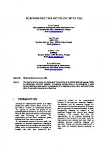
________________________________________________________________________________________________ Volume 43 form suitable to be a base for further software system oriented system analysis. The first one is to identify objects modeling. In classical approach this information is presented themselves. This task is solved by [13] – [14]. In general the as processes to be performed and information flows required analysis of entity relationship [15] can serve as a base for for process execution. Then this presentation of business object identification of the software system. And the second information has to be transformed into software system model, activity of object-oriented system analysis is so called which in object-oriented manner for software development “sharing of responsibilities” among objects, which is not so requires to present objects to interact in the form of UML trivial and is stated for solving by the author of the paper. The sequence diagram [3]. Sequence diagram shows objects, their main task to be defined is which operation will be executed by life lines and messages to be sent by objects-senders and which object and in which time sequence. performed by object-receivers. Sequence diagram is used to Rumbaugh [13] proposes to solve the problem of modeling present dynamic aspect of the system, which in object-oriented of object interaction with construction of sequence diagram approach is expressed in terms of message transfer among based on analysis of trace scenarios. Jacobson [16] in parallel objects. The dynamic of interactions is defined by an ordering with Rumbaugh proposes to base creation of sequence of the message sending and receiving actions. It serves as a diagram on description of use cases. Use case driven approach basis for definition of operations performed by objects to be is one of the methods for obtaining of object interaction. A set grouped into classes, as well as to present and to verify a of problems is related with the use cases in [17]. dynamic aspect of class state transition. As well as object-oriented approach views the both aspects The problem which is recently widely researched in the area of the system, the data and the operations, the modeling of of analysis of object interaction is formal transitions among problem domain already has to concentrates on both these models presented at the level of problem domain and system aspects. The two-hemisphere model driven approach [2] may realization expressed in terms of objects, if we are dealing be considered as a version of business process model driven with object-oriented software development and using Model approach. The approach addresses the following issues Driven Architecture (MDA) [8]. MDA is a standard, which currently relevant in software development: proposes the formal description of system with models, and requires definition of formal transitions among models. For • Business process models are usually developed in a now this transition is defined only informal, some guidelines comparatively high level of abstraction and rarely pin exist on how these transformations should be performed, but down all needed details for software development; formal algorithms or methods have not been defined yet. And • Diagrams preferred by business team differs from those therefore there is no CASE tool to support and manage the preferred by software developers. process of system modeling in UML by automatic generation of UML diagrams from formal or informal description of the Therefore the two-hemisphere model driven approach system. utilizes the problem domain concept model and the business The core of this paper is a hypothesis that business process process model for driving the software development process in and concept model contains enough information for sharing object-oriented manner. It is based on sophisticated models, responsibilities among objects and can serve as a base for but it enables the generation of simpler models from the definition of object interaction by using of UML sequence sophisticated ones in order to support development of diagram. Whereas UML sequence is stated as a one of stakeholders’ tacit knowledge. An essence of two-hemisphere ambiguous UML diagrams [9], with the implicit and informal model and its application for the definition of structural aspect semantic that designers can give to basic sequence diagram as of the system is described in the next section. a result of this conflict [10] – [12]. Two-hemisphere model [2] III. DEFINITION OF OBJECT CLASSES BASED ON TWOcontains information about business processes and concepts HEMISPHERE MODEL and has already been used for representation of object interaction with UML communication diagram in [6], where Two-hemisphere model driven (2HMD) approach [2] only static view of the system is investigated and an ordering proposes the application of business process modeling and of message sending and receiving is missed. Now the author concept modeling to represent systems in the platform tries also to find dependency between elements of two- independent manner and describes how to transform business hemisphere model and elements of UML sequence diagram, process models into UML models. For the first time the especially in its timing aspect. strategy was proposed in [18], where the general framework A nature of transition from business information into object for object-oriented software development was presented and interaction is found in the definition of which processes have the idea of the usage of two interrelated models for software to be performed in the system and which performer will system development was stated and discussed. The strategy execute exact process at the software level of system supports gradual model transformation from problem domain modeling. In order to identify a performer of the process at the models into program components, where problem domain software level of system presentation the process has to be models reflect two fundamental things: system functioning analyzed with the aim to define a software operation to (processes) and structure (concepts and their relations). execute the process and to notice the object to perform this Fig. 1 shows the schema of two-hemisphere model driven operation. So far two general steps can be defined for object- approach for system development [19].
38
Scientific Journal of Riga Technical University Computer Science. Applied Computer Systems
2010
________________________________________________________________________________________________ Volume 43 intermediate model. Then intermediate model is redrawn G2 G1 according to notational conventions of UML communication diagram (graph G3 in Fig. 1 and 2), using a set of concepts, defined in concept model – (model G2 in Fig. 1). Graph G3 Process model Concept model (P, U) corresponds to UML communication diagram, as discussed above. There is a set of nodes U= {A, B, C, D, E, F, G}, which is based on the same set of elements of concept G4 G3 model and represents objects, received from the set U’, and set of arcs P= {P1, P2, P3, P4, P5}, which represent interactions Class Communication diagram between objects in a form of methods to perform during object diagram interaction. During transition from G1 to G3 through Fig. 1. Transformations from two-hemisphere model into class diagram under intermediate model each process and each data flow is 2HMD approach transferred into corresponding elements of UML communication diagram [7]. The schema presents the way how elements of business The investigation of 2HMD approach under the statements process model (graph G1 in Fig. 1) and concept model (graph of MDA in [7] shows that approach could be applied for G2 in Fig.2) are transformed into elements of UML generation of several elements of class diagram, namely, to communication diagram (graph G3 in Fig.1) and then into generate class names, attributes, methods and several kinds of class diagram (graph G4 in Fig. 1). class relationships. The analysis of two-hemisphere model A notation of the business process model (graph G1 in Fig. proposed in [19] and the application of two-hemisphere model 1), which reflects functional perspectives of the problem and for knowledge architecture development in the task of study application domains, is optional, however, it must reflect program development presented in [6] make us to think that business processes and information flows [2]. And notational conventions of UML communication diagram is information flows have to be typed by corresponding concepts more suitable for definitions of formal transformations of twoin the concept model (graph G2 in Fig. 1), which is used in hemisphere model into object interaction and then into class parallel with business process model. A concept model [14] is diagram, than the application of UML sequence diagram. a variation of well known entity relationship (ER) diagram However, the aspect of time sequence, which is a notation [15] and consists of concepts (i.e. entities or objects) component of UML sequence diagram and is not shown in and their attributes. The notational conventions of twocommunication diagram, is missed in this case. And the author hemisphere model borrowed from GRAPES notation [20] give of the paper now is investigating the possibility to save time a possibility to address concepts in concept model to aspect in transition from two-hemisphere model into UML information flows (e.g. events) in process model. sequence diagram through the defined transformations in The transformations of graphs G1 and G3 using an accordance with an initial idea presented in [18]. intermediate model are shown in Fig. 2. The process model of two-hemisphere model is represented as a graph G1 (P, U), IV. DEFINITION OF OBJECT INTERACTION BASED ON TWOwhere P= {P1, P2, P3, P4, P5} is the set of system business HEMISPHERE MODEL processes, and U' = {A', B', C', D', E', F'} is the set of In UML models, objects interact to implement behavior. information flows among the processes, which in turn are UML has two kinds of diagrams to reflect object interaction – typed by concepts of concept model – a set U = (A, B, C, D, communication and sequence diagrams. Communication E, F, G) (not shown in Fig. 2). diagram allows observing the common interaction of objects Transformation of process model into so called intermediate in the system mainly focused on associations between objects model is made in a direct way of graph transformation [21], and time aspect is not stressed in the communication diagram. where the arcs of graph of business processes are transformed Sequence diagram shows interaction of objects for execution into nodes of intermediate model. And the nodes of graph of business processes are transformed into the arcs of of concrete use case or business function expressing time
G1
G3 I ntermediate m odel
P1
A’
P3
F’
C’
D’
P5
E’
P4
P2 F’
P5 P5
B’
Com munication diagram
P3
p1 ()
A’ : A
P3 C’
E’
p2
D’ P4
p 2 () ()
B’ : B ()
B’
P2
p3
P2
A’
()
P1
p3
Process model
p5 () F’ : F
p5
C’ : C
D’ : D
()
E’ : E
p4
()
Fig. 2. Graph transformations from graph of process model through intermediate model into UML communication diagram
39
Scientific Journal of Riga Technical University Computer Science. Applied Computer Systems
2010
________________________________________________________________________________________________ concept or type of information flow
information flow process applicant data
add applicant to group Process Model
Volume 43
group blank with applicant data
Applicant data
Group blank
name
time
ID
address
address
Concept Model
Concept in concept model defines a data structure for informatio n flow in process model. Here concept „Applicant data” is a type of information flo w „applicant data” in process model and concept „Group blank” is a type of informatio n flow „group bla nk with applicant data” in process model.
add_applicant _to_group () : Applicant _data
verb phrase
: Group_bla nk
Communic ation Diagram
: Applicant _data
noun phrase
: Group_blank
add_applicant _to_group () Sequence Diagram
Fig. 3. Analysis of verb and noun phrases in two-hemisphere model and related object interaction
aspect as a main focus of the modeling. Hypothetically, the transformation from two-hemisphere model into model of object communication is possible [7]. However, this paper analyzes the possibility to generate all the necessary information for object interaction (especially time component of that) in terms of UML sequence diagram. The definition of elements of sequence diagram needs an examination of elements of two-hemisphere model, which is presented as business process model related with concept model. Sequence diagram consists of objects, their life-lines and messages which they have to send to other objects. Object identification is based on the analysis of noun phrases in problem domain description [13], where it is presented in the form of twohemisphere model and contains the information about problem domain, where noun phrases are defined for events (arcs) of business process model and concepts of concept model (see Fig. 3). Therefore it is possible to suggest that description of an event in business process with its defined data structure in concept model can serve as a basis for identification of object in sequence diagram. The transformation of two-hemisphere model into communication diagram is performed in a direct way of graph transformation, where arcs of graph of business processes are transformed into the nodes of graph of object communication. As for UML sequence diagram, the description of an event in business process with its defined data structure in concept model can serve as basis for definition of object, which is a node of its life line. The analysis of verb phrase (see Fig. 3) makes it possible to suggest that the name of business process has to be a base for the definition of message of sequence diagram to be performed by object-receiver of this message. And if the name of the business process is defined in the form, where the first word is a verb, we can assume that the name of the exact message will be the same as the name of business process. According to the notation of sequence diagram in [3]
40
message has an object-sender and object-receiver of the message, which has to perform the action defined in the message. Direct transformation of graph of business processes into the graph of object communication defined in [6] solves the problem of identification of object-sender and object-receiver of the exact message by the application of several outlines of graph theory [21], where nodes of graph of business processes have to be transformed into arcs of object communication and arcs of graph of business processes and be transformed into nodes of object communication. The same assumption can be applied for the definition of objects in sequence diagram – object sender will be defined by incoming arc of exact process in the model of business processes and object-receiver will be defined by outgoing arc of exact process in the model of business processes (see an example in Fig.3). Therefore message defined for execution exact process in business process diagram will be sent by the object defined in the incoming arc of exact business process and received by the object in the outgoing arc of exact business process. Authors’ experiments on the assumptions proposed above have found the variety of combinations of input and output events for business processes. The problem of this variety is that it is not always possible to define the elements of sequence diagram in direct way. Several cases, where process has two incomes (e.g. process P2 in Fig. 2), requires an investigations on the definition of the object-sender of message. Whereas the construction of object communication and further definition of class structure was avoided to solve this problem, because the main aspect was stated as according with the aspect of who will be the object-receiver of the method. Moreover the variety of combinations of incoming and outgoing events under the transformations from twohemisphere model to communication diagram with further
Scientific Journal of Riga Technical University Computer Science. Applied Computer Systems
2010
________________________________________________________________________________________________ transition to class diagram gives a possibility to define Object : Class different relations among classes, for example aggregations, generalization and so on [22]. do / opera tion1() operation1 ()
operation2 ()
V. DEFINITION OF STATE TRANSITION BASED ON TWOHEMISPHERE MODEL
do / opera tion3()
Fragment of object interaction
is illustrated in Fig. 4. This example is trivial, since there are no choices or concurrency. In this case the creation is just simple transition from operations defined for object interaction into a form of state charts. The notational conventions of process model in two-hemisphere model gives an ability to operate also with more complicated object interactions and enables to define parallel and nested blocks of state charts. VI. AN ILLUSTRATIVE EXAMPLE OF TWO-HEMISPHERE MODEL APPLICATION The simplified version of the business process for the application of the pupil of the driving school is reflected in two-hemisphere model shown in Fig. 5. The sketch of the corresponding sequence diagram is shown in Fig. 6. Several fragments of the sketch of the sequence diagram allow discussing the ability to define more complicated set of elements, such as interaction frames for parallel operating and alternatives, different types of messages, and so on.
blanks of available groups
look for appropr iate gr oup applicant data
form list of teachers (director )
Applicant data
Group blank
name
time
ID
address
address
appr opriate group
add applicant to group
form list of instructors (dir ector )
gr oup blank with applicant data
assign start date of learning
teacher data
Corresponding sequence of operations
Fig. 4. Transition from object interaction expressed in UML sequence diagram into state charts
form gr oup (dir ector)
applicant data
do / opera tion2()
operation3 ()
As for sequence diagram, this variety may be a base for definition of timing aspect, and may serve for further modeling of object behavior with UML state transition diagram in correspondence with object-oriented manner for definition of class behavior. UML state charts are based on finite-state machines using an extended Harel’s [23] statechart notation and are used to represent behavior of an object. State charts describe internal object behavior using states and transitions among states. Such transitions are triggered by events, and they can include conditions [24]. As far as one hemisphere of two-hemisphere model is related to functional perspective of the system, it is possible to assume, that presentation of system behavior at the problem domain level can be naturally overcoming into elements of state charts through presentation of object interaction. Whereas the traditional way of mapping a sequence diagram lifeline to a state machine for that object is to have the operations sent to that object being trigger events of the transition and the messages which originate from that object as actions in a transition label. General schema of transformation of elements of object interaction into elements of statechart diagrams is shown in Fig. 4. As far as state charts are the most formal aspect of UML, they provide a natural basis for test data generation and can serve as a mean for verification of the transformations defined. To understand the last consideration, very simplified example
apply for learnin g (applicant )
Teacher data
Instructor data
name
name
load
load
instructor data
car
group blank with applicant datagroup blank with applicant data
assign teacher for group
assign instructor for applicant
group blank with applicant data and teacher
driving card
prepar e group register gr oup register for submission
assign learning dates group register with learning dates
dr iving car d with learning dates
learn theory (pupil)
Driving card
Group register
pupil
pupil
instructor
teacher
learning dates
gr oup data
examination data
learning dates examination data
learn driving (pupil )
Process model
Volume 43
Concept model
Fig. 5. Two-hemisphere model of the application of pupil to the driving school
41
Scientific Journal of Riga Technical University Computer Science. Applied Computer Systems
2010
________________________________________________________________________________________________ : Applicant par
: Applicant data
: Director
: Group blank
: Teacher data
: Instructor data
: Driving card
: Group register
Volume 43 : Pupil
apply for le arning ( ) form gr oup () look for appr opriate group () appropria te gr oup add applicant to group () assig n start date of lear ning () par
form list of teacher s () appropria te teacher assign teacher for group () for m list of instructor s () appropriate instr uctor assign instructor for applicant () prepare group register () par
assig n learning dates ( ) le arn theory
assig n learnin g dates () le arn driving
Sequence diagram Fig. 6. The corresponding UML sequence diagram transformed from two-hemisphere model shown in Fig. 5
: Group blank fo rm group()
do / form_group()
look f or a pp ropriate g roup()
do / look_for_appropriate_group()
add applicant to group()
do / add_applicant_to_group()
assign start date of learning() do / assign_start_date_of_learning() assign teacher for group()
Fragment of object interaction
do / assign_teacher_for_group()
Corresponding sequence of operations
Fig. 7. The sequence of object operations defined in the form of state chart generated from the corresponding fragment of object interaction.
For example, the fact that y-axis is a time axis in both diagrams (process model and sequence diagram) and semantic conventions for process modeling that process can be performed when all incoming information flows are generated from their execution processes. It gives author to assume that process “form list of teachers” and “form list of instructors” with all their successors, which are two parallel fragments in process model, seem to be disjunct fragments in the resulting UML sequence diagram. Therefore the corresponding sequence of message sending is taken into parallel interaction frame. In addition, the diagram starts with two messages sent at the same time, but really the system requires, that both processes have to be completed before the process “look for appropriate group” should start. For now the interaction frame for parallel messages is arranged for both messages to be sent, but this
42
states a set of possible directions for future research on application of two-hemisphere model for object-oriented modeling of the system in UML. One more interesting fragment of object interaction is the process “assign learning dates”. The fact, that the process has two outgoing information flows, which are defines as ones of different data type, let author to assume, that control message “assign learning dates” should be sent to both objects – “group register” and driving card”. As well as for this “artificial” example this assumption is proved also for several more sophisticated real world examples, where all the analogical fragments give the same result. The state transition diagram generated for the fragment of object behavior is shown in Fig. 7. VII. CONCLUSIONS The purpose of a model-driven approach is to structure the modeling process, providing the base of research directions which explain how to consider general models and relate them with more specific information about platforms, performance and so on. Two-hemisphere approach is already successfully applied for encapsulation of attributes and methods into system classes [7], as well as the definition of relationships between classes is presented in [22]. The ideas presented in this paper are a step forward of the author’s investigations in the application of two-hemisphere model for software system development in object-oriented manner and the generation of different elements of system model viewing the system from different aspect. The contribution of the paper can thus be summarized as follows. First, author identifies how concepts used at different levels of object-oriented software design fit together: • at the level of domain modeling two-hemisphere model is considered;
Scientific Journal of Riga Technical University Computer Science. Applied Computer Systems
2010
________________________________________________________________________________________________ Volume 43 • at the level of software modeling UML sequence diagram, [5] C. W. Chan, “Knowledge and software modeling using UML,” Software and Systems Modeling (SoSyM), vol. 3, no. 4, pp. 294-302, December class diagram and state transition are received in the way 2004. of formal transitions from elements of two- hemisphere [6] O. Nikiforova, M. Kirikova, and N. Pavlova, “Principles of model driven architecture in knowledge modeling for the task of study program model into elements specified by UML. evaluation,” in Databases and Information Systems IV, O. Vasilecas, J. As far as two-hemisphere model driven approach introduces Eder, and A. Caplinskas, Eds. IOS Press, Series “Frontiers in Artificial another (additional) modeling step between system Intelligence and Applications,” 2007, pp. 291-304. specification and software development, the question is [7] O. Nikiforova and N. Pavlova, “Open work of two-hemisphere model transformation definition into UML class diagram in the context of whether the benefits of formal transformation prevail or not. MDA,” in Preprint of the Proceedings of the 3rd IFIP TC 2 Central and But modeling of business processes and preliminary data East Europe Conference on Software Engineering Techniques, CEEstructure is not new strategy for requirement analysis and SET, October 2008. Brno, pp. 133-146. guide version 1.0.1.” [Online]. Available: companies are common with business process modeling [8] “MDA http://www.omg.org/cgi-bin/doc?omg/03-06-01.pdf. [Accessed: techniques or at least they employ particular business process September 2009]. description frameworks. [9] C. Sibertin-Blanc, O. Tahir, and J. Cardoso, “Interpretation of UML sequence diagrams as causality flows,” in Advanced Distributed This fact and existence of many commercial business Systems, 5th International School and Symposium (ISSAD). Heidelberg: modeling tools (such as ARIS, IBM products, Sparx Software Springer, LNCS, vol 3563, 2005, pp. 126-140. Architect etc.) and their open source analogues are a strong [10] R. Alur, K. Etessami, and M. Yannakakis, “Inference of message sequence charts,” in Proceedings of the 22nd International Conference motivation to base software development on the business on Software Engineering (ICSE). New York: ACM Press, 2000, pp. 304process model rather than on any other soft or hard models. 313. Therefore formal transformation of two-hemisphere model [11] S. Uchitel, J. Kramer, and J. Magee, “Detecting implied scenarios in message sequence chart specifications,” in Proceedings of the 9th into UML diagrams shall step in and try to acquire software European Software Engineering Conference and 9th ACM SIGSOFT requirements. International Symposium on the Foundations of Software Engineering This paper shows the strategy of two-hemisphere model (ESEC/FSE’01). New York: ACM, 2001, pp. 74-82. application for generation of UML sequence diagram and its [12] B. D. Aredo, “A framework for semantics of UML sequence diagrams in PVS,” J Univers Comput Sci (JUCS), vol. 8, no. 7, 2002, pp. 674-697. further usage for construction of class state transitions. The [13] J. Rumbaugh, M. Blaha, W. Premerlani, F. Eddy, and W. Lorensen, two-hemisphere model driven approach proposes to apply Object Oriented Modeling and Design. New Jersey, Englewood Cliffs: transformations from business process model in conjunction Prentice-Hall, Inc, 1991. with concept model into scenarios for object interactions by [14] C. Larman, Applying UML and Patterns: An Introduction to ObjectOriented Analysis and Design, 3rd ed. New Jersey: Prentice Hall, 2005. direct transformation of object messages from the elements of [15] P. Chen, “The entity relationship model – towards a unified view of process model. Appropriate interacting objects are extracted data,” ACM Trans. Database Systems, vol. 1, 1976, pp. 9-36. [16] I. Jacobson, G. Booch, and J. Rumbaugh, The Unified Software from the elements of concept model. Development Process. Addison-Wesley, 2002. A tool for generation of class diagram from two-hemisphere [17] N. Pavlova and O. Nikiforova, “Formalization of two-hemisphere model model is developed and presented in [25]. The refinement of driven approach in the framework of MDA,” in Proceedings of the 9th Conference on Information Systems Implementation and Modelling, the tool with an ability to define elements of object interaction Czech Republic, Prerov, March 2006, J. Štefan, Ed. Ostrava: MARQ, in the form suitable for UML diagramming tools can be 2006, pp. 105-112. defined as a step for author’s future research. [18] O. Nikiforova, “General framework for object-oriented software ACKNOWLEDGMENTS The research reflected in the paper is supported by the research grant No. FLPP-2009/10 of Riga Technical University “Development of Conceptual Model for Transition from Traditional Software Development into MDA-Oriented.” The research reflected in the paper partly is supported by Grant of Latvian Council of Science No. 09.1245 "Methods, models and tools for developing and governance of agile information systems".
[19]
[20] [21]
REFERENCES [1] [2]
[3]
[4]
S. R. Schach, Object-Oriented & Classical Software Engineering, 7th ed. McGraw-Hill Education, 2007. O. Nikiforova and M. Kirikova, “Two-hemisphere model driven approach: engineering based software development,” in The 16th International Conference Advanced Information Systems Engineering Caise’2004, September 2004, A. Persson and J. Stirna, Eds. Berlin Heidelberg: Springer-Verlag, LNCS 3084, pp. 219-233. “Unified modeling language: superstructure v.2.2,” Object Management Group. [Online]. Available: http://www.omg.org/spec/UML/2.2/ Superstructure. [Accessed: September 2009]. Object Management Group. [Online]. Available: http://www.omg.org. [Accessed: September 2009].
[22]
[23] [24]
development process,” in Scientific Proceedings of Riga Technical University, Computer Science, Applied Computer Systems, vol. 13. Riga: RTU, 2002, pp. 132-144. O. Nikiforova, N. Pavlova, and J. Grigorjevs, “Several facilities of class diagram generation from two-hemisphere model in the framework of MDA,” in Proceedings of 23rd International Symposium on Computer and Information Sciences (ISCIS 2008), Istanbul, Turkey, October 2008. [Online]. Available: IEEE Xplore – http://ieeexplore.ieee.org. GRADE Business Modeling. Language Reference. INFOLOGISTIK GmbH. 1998. J. Grundspenkis, “Causal domain model driven knowledge acquisition for expert diagnosis system development,” in Lecture Notes of the Nordic-Baltic Summer School on Applications of AI to Production Engineering, Kaunas, Lithuania, 9-14 June 1997, K. Wang and H. Pranevicius, Eds. Kaunas: Kaunas University of Technology Press, 1997. O. Nikiforova and N. Pavlova, “Foundations on generation of relationships between classes based on initial business knowledge,” in 17th International Conference on Information Systems Development (ISD2008), Paphos, Cyprus, August 25-27, 2008, Information Systems Development, G. A. Papadopoulos, W. Wojtkowski, W. G. Wojtkowski, S. Wrycza, and J. Zupancic, Eds. New York: Springer-Verlag, 2009, pp. 289-297. D. Harel, “State charts: a visual formalism for complex systems,” in Science of Computer Programming, Vol. 8, 1987. A. Baldini, A. Benso, and P. Prinetto. “System-level functional testing from UML specifications in end-of-production industrial environments,” in Software Tools Technol Transfer, Vol. 7. Springer-Verlag, 2004, pp. 326-340.
43
Scientific Journal of Riga Technical University Computer Science. Applied Computer Systems
2010
________________________________________________________________________________________________ [25] O. Nikiforova and N. Pavlova, “Development of the tool for generation of UML class diagram from two-hemisphere model,” in Proceedings of the Third International Conference on Software Engineering Advances (ICSEA), International Workshop on Enterprise Information Systems (ENTISY), October 2008, H. Mannaert, C. Dini, T. Ohta, and R. Pellerin, Eds. IEEE Computer Society, Conference Proceedings Services (CPS), 2008, pp. 105-112.
Volume 43
Oksana Nikiforova has received engineering science doctor’s degree (Dr.sc.ing) in information technologies sector (system analysis, modeling and designing, sub-sector) from the Riga Technical University, Latvia, in 2001. She is presently an Associated Professor in the Department of Applied Computer Science of Riga Technical University, where she has been on the faculty since 1999. Her current research interests include object-oriented system analysis and modelling especially its issues in the framework of Model Driven Architecture. In these areas she has published extensively and has been awarded several grants. She has participated and managed several research projects related to the system modeling, analysis and design, as well as participated in several industrial software development projects.
Oksana Ņikiforova. Sistēmas modelēšana vienotajā modelēšanas valodā ar divu pusložu modeli vadāmo pieeju Objektorientēta sistēmas modelēšana programmatūras izstrādes sākumā var būt uzskatīta kā vispusīga zināšanu attēlošana, kas ļauj izstrādātājam lietot problēmas vides attēlojumu (koda vietā) atkārtotai lietošanai un atbildību sadalīšanai starp sistēmas objektiem pietiekami augstajā sistēmas abstrakcijā. Vienota modelēšanas valoda (UML) ir industriālais standarts programmatūras specifikācijai, modelēšanai un programmatūras izstrādei, lietojot objektorientētu tehnoloģiju. UML nav metodoloģija sistēmas modeļa un programmatūras izstrādei, bet tikai notācijas pieņēmumi, kas norāda kā apzīmēt modeļa elementus. Un izstrādātājiem ir spiesti identificēt modeļa elementus no problēmas vides, vadoties pēc atsevišķām rekomendācijām vai balstoties uz savu intuīciju. Tas var izraisīt un bieži vien izraisa situācijas, kad izveidotais sistēmas modelis neatbilst problēmas videi vai satur pretrunīgu informāciju, informācijas zudumus vai dublēšanas. Rakstā ir piedāvāts lietot divpusložu modeļvadāmo pieeju sistēmas modelēšanai problēmvides līmenī, lai izvairītos no problemātiskām situācijām, kas rodas intuitīvas vai manuālas modeļa izstrādes gadījumā. Raksts ilustrē kā divpusložu modelis var būt transformēts UML izteiktā programmatūras modelī, lietojot grafu transformācijas likumus. Kursantu pieteikšanās mācībām autoskolā abstraktais piemērs ir lietots, lai ilustrētu piedāvātas idejas realizāciju. Оксана Никифорова. Моделирование системы на UML с помощью подхода, основывающегося на двух-полушариевой модели Объектно-ориентированное моделирование системы на начальном этапе разработки программного обеспечения позиционируется как всестороннее отображение знаний, которое в свою очередь позволяет разработчикам использовать модель проблемной области (вместо кода) для повторного использования и распределения ответственности между классами системы на достаточно высогом уровне абстракции. Единый язык моделирования (англ. Unified Modeling Language - UML) является индустриальным стандартом в области спецификации, моделирования и разработки программного обеспечения, а именно используя объектно-ориентированный подход. UML не является методологией для разработки модели системы и соответственно не содержит описания этапов построения модели и правил идентификации элементов из описания проблемной области, а описывает только систему обозначения элементом модели и является средством «рисования» модели. Таким образом разработчики вынуждены следовать отрывистым рекомендациям по разработке модели системы из различных источников и своей интуиции, что в свою очередь может привести и зачастую приводит к ситуациям, когда модель системы содержит несоответствующую проблемной области информация, которая так же является недостаточной, противоречивой или неполной. В статье предлагается использовать подход, основывающийся на двух-полушариевой модели, чтобы избежать подобных проблематичных ситуаций. Статья иллюстрирует как двух-полушариевая модель может быть трансформирована в диаграммы, описанные на языке UML, с помощью законов преображения графов. С помощью абстрактного примера записи курсанта в автошколу показана реализация предложенной идеи.
44