System Requirements for Mini-MOST Experiment
Last modified: 3/11/2004
System Requirements for Mini-MOST Experiment
Narutoshi Nakata1(
[email protected]) Guangqiang Yang1(
[email protected]) Billie F. Spencer, Jr.1(
[email protected])
1UIUC
MUST-SIM Facility, Urbana, IL
University of Illinois at Urbana-Champaign Department of Civil and Environmental Engineering, MUST-SIM Facility
http://nees.uiuc.edu/
System Requirements for Mini-MOST Experiment
Last modified: 3/11/2004
1. Introduction The main purpose of the Mini-MOST experiment is to show the capability of major NEESgrid service components using a small-scale physical experiment setup. Comparing with the Multi-site Online Simulation Test (MOST) conducted on July 30, 2003, the Mini-MOST experimental hardware, as implied by its name, is small in size and can be easily packed and shipped to other places. However, the software involved in this experiment is similar to what was used for the MOST experiment and provides the same level of functionality and services. Therefore, Mini-MOST experiment provides a desirable platform for students and researchers to be familiar with the NEESgrid software and to gain first-hand experience before conducting fullscale experiment. Moreover, the Mini-MOST experiment can also be utilized for the purposes of educational demonstration and software installation debugging. This document provides some brief background information on the employed multi-site online simulation test scheme and detail description of hardware and software requirements for the Mini-MOST experiment.
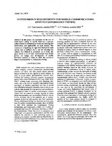
2. Multi-Site Online Simulation Test Figure 1 shows the schematic of the multi-site online simulation test scheme. In this modular framework, four distinct modules are included: • Simulation Coordinator • Master Computational Module
Figure 1. Schematic of the Multi-Site Online Simulation Test Scheme.
University of Illinois at Urbana-Champaign Department of Civil and Environmental Engineering, MUST-SIM Facility
http://cee.uiuc.edu/research/nees
Page 2
System Requirements for Mini-MOST Experiment
Last modified: 3/11/2004
• Slave Computational Module • Experimental Module In the center of this scheme, it is the Simulation Coordinator (SC) which acts as the command center for the overall experiment. The SC sends the requests for specific action to and receives replies from individual module through NEESgrid Tele-Operation Control Protocol (NTCP) and a plug-in interface (more information regarding NTCP can be found at http:// www.neesgrid.org/news/documents.php). This architecture provides great flexibility allowing each module to run in geographically remote locations and only requiring each module to interface with SC through NTCP. The master computational module (NCSA) performs the numerical integration, combining results from the experimental (Mini-MOST) and slave computational node (UIUC). At each time step, the master computational module numerically calculates the frame’s response and send the target displacement and rotation at the substructure connection points to the SC through NTCP. It waits until receiving the measured force and moment response from experimental and/or slave computational modules before the numerical integration proceeds. The integration scheme used in the simulation is an alpha-operator splitting method. The unique feature for this framework is the interchangeability between the experimental and slave computational modules. Therefore, experiments can be debugged using the computational modules, minimizing the risk of unexpected damage to the physical structure/hardware. The data collected during the experiment is saved in the local data storage and/or transferred in real-time to the central repository in the local NEESPOP using Samba. Once the data is in the central repository, remote observers can view the experimental data using various visualization tools within the web-based CHEF environment. Tele-observation is one of the main features of the NEESgrid services.
3. Hardware Requirements Figure 2 provides an overhead view of the Mini-MOST experiment. The hardware of this experiment can be basically divided into three categories: specimen experimental setup, computers and instrumentation. 3.1 Specimen Experimental Setup The test specimen for the Mini-MOST experiment is a steel beam with a rectangular cross section (as shown in Fig. 3a). The length of the beam is 40 inches with a width of 0.4 inches and height of 2 inches. The beam is fixed at one end by two L-shaped anchorages, as shown in Fig. 3b. The whole experiment is mounted on a 48 by 30 inch (standard size for the computer desk) aluminum base plate. The base plate has 4 fixed legs at the each corner and 2 adjustable legs in the middle to keep it level and prevent bending.
University of Illinois at Urbana-Champaign Department of Civil and Environmental Engineering, MUST-SIM Facility
http://cee.uiuc.edu/research/nees
Page 3
System Requirements for Mini-MOST Experiment
Last modified: 3/11/2004
Figure 2. Overhead View of the Mini-MOST Experiment. (a)
(b)
Figure 3. (a) Steel Beam; (b) L-Shape Anchorages. To eliminate the rotational motion of the stepper motor lead screw, an anti-spin mechanism using linear guide is designed and installed. With this mechanism, only translational motion of the lead screw is allowed. To minimize the lateral load on the load cell, a pivot mechanism and bearing are installed between the load cell and beam and between the motor box and base plate, respectively. Moreover, a similar pivot mechanism is also utilized between the LVDT and beam such that only the lateral deformation of the beam is measured. Detailed plans for the experimental design will be reported in another document and is currently being written. 3.2 Computers 3.2.1 Mini-MOST Computer The Mini-MOST computer is used for stepper motor control and data acquisition, as well as NTCP communication between the Mini-MOST and Simulation Coordinator. It is desirable that the computer is installed with Windows XP operating system and has a minimum 2.0 GHz
University of Illinois at Urbana-Champaign Department of Civil and Environmental Engineering, MUST-SIM Facility
http://cee.uiuc.edu/research/nees
Page 4
System Requirements for Mini-MOST Experiment
Last modified: 3/11/2004
CPU speed, 512 MB memory, 80 GB hard drive and 2 PCI slots. 3.2.2 Simulation Computers The simulation computers are utilized to simulate the frame response numerically. The simulation code is written in MATLAB 6.5. During the experiment, at least one simulation computer is required to run the master computational module. However, when multiple computational nodes are involved, you have the option of running both master and slave computational modules in one computer or in separated computers. Simulation computers need to have a minimum 1 GHz CPU speed, 256 MB memory and are installed with MATLAB 6.5. If the simulation becomes complicated, the computer configuration needs to be upgraded accordingly. 3.2.3 NEESpop Server NEESpop is a Linux server installed with NEESgrid software to provide essential services for the experiment. This software package includes CHEF, grid services, NTCP, etc. The server must have a minimum 1 GHz CPU speed with dual processors, 1GB RAM, 2 PCI slots, 36 GB SCSI hard disk, dual gigabit ethernet cards, and be installed with Redhat Linux 7.2 or 7.3. The current NEESgrid software (release 2.2) can be downloaded at http://neesgrid.org/software/ neesgrid2.2/. 3.2.4 Optional Tele-Presence Server The tele-observation is optional for the Mini-MOST experiment. To achieve the teleobservation, a system installed with NEES tele-presence software needs to be employed. The minimum configuration for this Linux based system include 1 GHz CPU speed with dual processors, 1 GB RAM, 2 PCI slots, 36 GB SCSI disk, dual gigabit ethernet cards. In addition, you also need Axis 2401 Internet Appliance Video Server and tele-robotic camera with PZT capability. The tele-presence system can support up to 5 video servers and 5 video cameras at the same time. 3.3 Instrumentation 3.3.1 HSI Size 23 Non-Captive Linear Actuator An HSI size 23 non-captive linear actuator is used to impose the desired displacement to the beam. This non-captive bipolar stepper motor has a 10-inch long lead screw, thus a ±3 inch stroke. The travel per step is 0.002 inch, the input voltage is 5 volts DC, and maximum thrust force of 25 lb. To prevent the rotation of lead screw, an L-shape anti-spin mechanism is designed. As shown in Fig. 4, the stepper motor lead screw is fixed to the anti-spin mechanism
Figure 4. HSI Size 23 Non-Captive Bipolar Linear Actuator.
University of Illinois at Urbana-Champaign Department of Civil and Environmental Engineering, MUST-SIM Facility
http://cee.uiuc.edu/research/nees
Page 5
System Requirements for Mini-MOST Experiment
Last modified: 3/11/2004
by a set screw. The anti-spin mechanism, in turn, connects to the motor box with a linear guide. This linear guide eliminates the rotational motion of the lead screw; thus, only translational motion is allowed. Moreover, a bearing is installed at the bottom of the motor box which allows the motor and anti-spin assembly to rotate in the horizontal plane thus minimizing the lateral force imposed on the load cell. 3.3.2 NI MID-7602 Servo Motor Drive To drive the linear actuator, a National Instruments MID-7602 integrated stepper motor power drive (Fig. 5a) is employed. This micro-stepping enabled motor drive can control 2 stepper motors at the same time with a maximum current of 1.4 Amp/phase. In addition, this drive provides convenient connections for motion I/O signals and all features of a universal motion interface (UMI) wiring module. 3.3.3 NI PCI-7342 Motion Control Hardware The National Instruments PCI-7342 board (Fig. 5b) provides the real-time control of the stepper motor using either digital encoder or external analog feedback. This hardware also supports motion linear interpolation, 32 bits of digital I/O for high-speed capture, and the RTSI bus for powerful real-time integration. 3.3.4 NI SHC68-C68-S Cable This cable connects the PCI-7342 motion control hardware and MID-7602 stepper motor drive. (a)
(b)
Figure 5. (a) MID-7602 Stepper Motor Drive; (b) PCI-7342 Motion Control Hardware.
3.3.5 NI PCI-6036E DAQ Board The National Instruments PCI-6036E (Fig. 6a) is a 16-bit DAQ board with a maximum rate of 200 kilo samples/sec. The NI PCI-6036E has sixteen-channel analog inputs when it operates under single-end mode and two ±10 volt analog outputs.
University of Illinois at Urbana-Champaign Department of Civil and Environmental Engineering, MUST-SIM Facility
http://cee.uiuc.edu/research/nees
Page 6
System Requirements for Mini-MOST Experiment
Last modified: 3/11/2004
3.3.6 NI BNC-2110 BNC Connector Box The BNC-2110 BNC connector box (Fig. 6b) is a shielded connector block with signallabeled BNC connectors. The BNC-2110 connector block simplifies the connection of analog signals, some digital signals, and two user defined connections to the DAQ device. 3.3.7 NI SH68-68-EP, Shielded Cable, 1m The SH68-68-EP 68-pin Shielded Cable connects the PCI-6036E DAQ board with the BNC-2110 BNC connector box. (b)
(a)
Figure 6. (a) PCI-6036E DAQ Board; (b) BNC-2110 BNC Connector Box. 3.3.8 Omega LC-201 Load Cell To measure the restoring force of the beam, an Omega LC-201 load cell is used. This 25-lb load cell is a subminiature tension and compression strain-type force sensor with a diameter of 0.75”. At 10-volt excitation, the load cell has a sensitivity of 1 mv/lb. To prevent the lateral force acting on the load cell, a pivot (as shown in Fig. 7) is installed between the beam and load cell in addition to the bearing installed at the bottom of the motor box.
Figure 7. Omega LC-201 Load Cell.
3.3.9 Strain Gauge A standard strain gauge, as shown in Fig. 8, is attached at the end of the beam to measure the strain induced by the beam deformation. Although strain gauge measurement is not used for feedback and simulation, it is utilized as secondary measurement for load cell and LVDT reading verification and visualization. 3.3.10 Omega BCM-1 Strain Gauge Bridge Completion Module The BCM-1 bridge completion module (Fig. 8) pro-
Figure 8. Strain Gauge and Bridge Completion Module.
University of Illinois at Urbana-Champaign Department of Civil and Environmental Engineering, MUST-SIM Facility
http://cee.uiuc.edu/research/nees
Page 7
System Requirements for Mini-MOST Experiment
Last modified: 3/11/2004
vides a convenient means of completing the Wheatstone Bridge circuit used for strain gauge measurement. The module can be used for quarter-bridge measurements with 120 or 350 Ohm gauges, or for half-bridges with gauges of any resistance. 3.3.11 Omega DP25B-S-A Strain Gauge Meter Two Omega DP25B-S-A strain gauge meters (Fig. 9) are used in the Mini-MOST experiment. One meter is for load cell, and the other one is for strain gauge. The DP25B meters provide excitation voltages to sensors, read measurements back and amplify sensor signals before they are sent to the DAQ system. Moreover, the front LED panel of the meter can be configured to display sensor readings in physical unit. As shown in Fig. 9, the amber reading provides the load cell measurement in Newton, and the green reading gives the strain gage measurement in micro-strain.
Figure 9. Omega DP25B-S-A Strain Gauge Meter.
3.3.12 Schaevitz 3000 DC-EC LVDT, power supply and mounting block The Schaevitz 3000 DC-EC Linear Variable Differential Transformer (LVDT), as shown in Fig. 10, is used to measure the displacement of the beam from the initial position. The stroke of this LVDT is ±3 inch with a sensitivity of 3.33 volt/inch. The 15-volt excitation voltage is provided by a Schaevitz LVDT power supply. LVDT measurement is sent to both NI MID-7602 for displacement feedback control of the stepper motor and DAQ board.
Figure 10. Schaevitz 3000 DC-EC LVDT.
4. Software Requirements The Mini-MOST experiment is based on the several communication techniques. Figure 11 shows the NTCP architecture with the Mini-MOST experiment. As shown in the figure, communication between the SC and NTCP servers uses NEESgrid NTCP service. Communication between M plug-in and Matlab backend programs is OGSA based whereas communication
University of Illinois at Urbana-Champaign Department of Civil and Environmental Engineering, MUST-SIM Facility
http://cee.uiuc.edu/research/nees
Page 8
System Requirements for Mini-MOST Experiment
LV-Plugin
ASCII
Last modified: 3/11/2004
Labview System Control Deamon
NTCP Server NT CP
Control Program DAQ Mini-MOST PC
M-Plugin MATLAB (Simulation Coordinator)
OGSA
NTCP
MATLAB (Master Computation)
M-Plugin
MATLAB (Slave Computation)
NTCP Server
M-Plugin CP NT
M-Plugin
OGSA
NTCP Server NEESPOP
Simulation PC
Figure 11. NTCP Architecture for the Mini-MOST Experiment. between LV plug-in and ‘Control daemon’ is ASCII based. To implement all functionality, following software is required on each machine. 4.1 Mini-MOST Computer • LabVIEW Full Package: The Mini-MOST experiment is running on the National Instruments LabView system. The main LabView programs for the Mini-MOST experiment include: ‘Control Daemon’ for communication with NEESpop, ‘Control Program’ for the stepper motor control and ‘DAQ’ for data acquisition of sensor data. These programs were developed by the NEESgrid System Integrator (SI) Team. • LabVIEW Internet Tookkit: easily incorporate a variety of electronic communications capabilities, such as XML, CGI, and FTP transfers into your virtual instrumentation applications • NI Motion Assistant for Motion Control Programming: a flexible and easy-to-use development tool for building and prototyping motion applications, gives you the ability to quickly develop motion control systems. Mini-MOST LabVIEW software can be downloaded at the http://www.neesgrid.org/software/neesgrid2.2 and detail instruction can be found at http://www.mcs.anl.gov/neesgrid/mmost/.
University of Illinois at Urbana-Champaign Department of Civil and Environmental Engineering, MUST-SIM Facility
http://cee.uiuc.edu/research/nees
Page 9
System Requirements for Mini-MOST Experiment
Last modified: 3/11/2004
4.2 Simulation Computer • Matlab 6.5: Matlab 6.5 is required to run the Matlab backend programs, ‘NCSA_Comp_Site.m’ and ‘UIUC_Exp_Site.m’. • Simulation Software: Matlab simulation code is required to run the SC, master and slave computational modules, etc. and can be downloaded at http://www.neesgrid.org/ software/neesgrid2.2. • OGSA 3.0: OGSA3.0 is required to set up the communication between Matlab backend programs and M plug-in on NEESpop. OGSA can be downloaded on the SI web site. • Java: A Sun Java JDK or JRE version 1.3.1_01 or higher has to be installed. It can be downloaded at http://java.sun.com/j2se/1.3/download.html. • Ant: The Ant build tool must be installed - version is 1.5.1 or greater. It can be downloaded at http://apache.mirror.digitalspace.net/ant/binaries/apache-ant-1.5.3-1bin.zip. • Junit: Junit has to be installed to run the tests. It can be downloaded at http://prdownloads.sourceforge.net/junit/junit3.8.1.zip?download. 4.3 NEESpop Server • NEESgrid 2.2: NEESgrid 2.2 is required on NEESpop to employ the NTCP server program to communicate with the client, that is the SC in the Mini-MOST experiment. • Plug-ins: Two plug-ins need to be installed: Matlab (M) plug-in and LabView (LV) Plug-in. M plug-in communicates between NTCP server and Matlab backend programs, ‘NCSA_Comp_Site.m’ and ‘UIUC_Exp_Site.m’. LV plug-in interface is required for the communication between NTCP server and LabView backend program, ‘Control Daemon’. After all these software are installed, all software environments have to be properly configured referring to ‘nees-ntcp-install-win’.
5. Conclusions The NEESgrid architecture contains a substantial number of interacting components and services. Mini-MOST represents an inexpensive but comprehensive means for research programmers to interact with and learn these components without tying up more expensive or delicate research equipment. Because the software is a close counterpart to that of a full-scale NEES experiment – the MOST experiment of July, 2003 – Mini-MOST offers a working reference implementation of NEESgrid services, allowing NEES research programmers to see first-hand how the software and hardware components interact. It is anticipated that Mini-MOST will also
University of Illinois at Urbana-Champaign Department of Civil and Environmental Engineering, MUST-SIM Facility
http://cee.uiuc.edu/research/nees
Page 10
System Requirements for Mini-MOST Experiment
Last modified: 3/11/2004
become part of the NEESgrid training materials being developed by NCSA for delivery to the NEES Consortium in 2004.
University of Illinois at Urbana-Champaign Department of Civil and Environmental Engineering, MUST-SIM Facility
http://cee.uiuc.edu/research/nees
Page 11
Table 1. Price List for the Mini-MOST Experimental Setup Product Name 1 2
3
4
5 6 7
8
9
Part No.
Dell Dimension 4600 DAQ Computer NI MID-7602 Stepper Motor Drive 1 1 NI PCI-7342 Motion Control Hardware 1 NI SHC68-C68-S Cable 1 NI PCI-6036E DAQ Board 1 NI BNC-2110 Connector Box 1 NI SH68-68-EP, Shielded Cable, 1 m Omega DP25B-S-A Strain Gauge Meter Omega LC-201Load Cell Omega BCM-1 Strain Gauge Bridge Schaevitz 3000 DC-EC LVDT Schaevitz LVDT power supply Schaevitz LVDT mounting block HSI Size 23 Non-Captive Linear Actuator NEESPOP Linux Server Telepresence Linux Server Axis 2401+ Video Server2 2 Sony EVI-D100 PTZ camera Broadware Streaming Server Software for RH Linux Matlab License Labview Full Package Labview Internet Developers Toolkit NI Motion Assistant SW for Motion Control Programming Material and Labor Cost for Machining Total:
778003-01 778665-02 186380-02 778465-01 777643-01 184749-01 DP25B-S-A LC201-25 BCM-1 3000 DC-EC PSD 4-15 DC 04560950-000 57F42-05-002ENG
776671-03 777343-01 778553-01
Quantity 1 1 1 1 1 1 1 2 1 1 1 1 2 1 1 1 1 1 1 1 1 1 1
Price $
$
1,800.00 1,795.00 895.00 150.00 745.00 295.00 105.00 650.00 485.00 68.00 454.00 145.00 48.00 118.00 2,500.00 2,000.00 800.00 900.00 2,000.00 500.00 498.75 123.75 198.75 3,000.00
Specification DAQ PC with MS Windows OS and 3 PCI slots 2-axis servo power drive, max 1.4A/phase, 24 volt output 2-axis motion controller for stepper or servo motors Cable connecting the MID-7652 and PCI-7342 200 kS/s, 16-bit, 16 SE analog input and 2 analog output BNC connector box Cable connecting the PCI-60136E and BNC-2110 Strain meter with 0-10 volt analog output 25 lb strain-type load cell Strain gauge completion bridge Plus/minus 3 inch stroke 4-15 volt DC LVDT power supply Mounting block for E series LVDT Maximum thrust up to 25 lb with 10 inch lead screw
North America Academic Price North America Academic Price North America Academic Price North America Academic Price The price is estimated based on the rate at UIUC, single actuator version
20,274.25
1. National Instruments provides 10% discount to eudcational institution on hardware purchase. 2. The Axis 2401+ video server and Sony EVI-D100 PTZ camera can be replaced by an Axis 2130 network PTZ camera which has a built in video server. The cost is about $1600.
MiniMOST Single Actuator Version 1.0