elling approach to the Paderborn Shuttle system application. Story Driven .... Since this loop applies also to step four of the story board, we need a branch ...
Systematic Story Driven Modeling, a case study Ira Diethelm, Leif Geiger, Albert Z¨undorf
SE, Universit¨at Kassel Wilhelmsh¨oher Allee 73, 34121 Kassel (ira.diethelm | leif.geiger | albert.zuendorf)@uni-kassel.de http://www.se.e-technik.uni-kassel.de/se
1
Introduction
This paper is a case study applying our story driven modelling approach to the Paderborn Shuttle system application. Story Driven Modeling (SDM) aims to provide a very systematic process for the development of object oriented software , cf. [KNNZ00, Zuen01]. A crucial step of SDM is the derivation of general behavior specifications from a number of analysis scenarios. Based on a large number of educational and research projects and based on some first trials in industrial projects, in [DGMZ02, DGZ02, DGZ03] we have developed a systematic guideline for this step. The case study of this paper applies these guidelines to the Paderborn Shuttle system and shows the feasibility of our approach. In the following sections we describe the central phases of SDM with an emphasis on the derivation of operational behavior specifications. Then we give conclusions and future work.
2
Story Boarding - refining use cases
Our approach starts with the usual requirements elicitation resulting in use case diagrams and structured use case descriptions. In this paper, we use the workshop case study of the Paderborn Shuttle System as a running example. Each use case scenario consists of a description of the start situation, an invocation, an elicitation of all executed steps and a description of the resulting situation. To elaborate the use case scenarios, the developers may perform a so-called object game. This may be done in a team session. The developers may use an object diagram on a white board. During the scenario execution the object structure evolves. This is protocolled as sequences of object diagrams, e.g. using a digital camera or a smart board. The results of the object game should now be turned into so-called story boards, e.g. within the Fujaba tool. A story
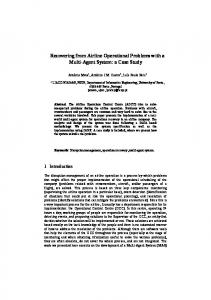
board is a sequence of UML collaboration diagrams that show the changes of the object structure in this scenario comic strip alike. During story boarding many details are added to the scenarios, that are usually skipped during the team based object game. Examples are object and attribute types, link names, auxiliary objects and even intermediate steps. While the object game is a group activity, story boarding may be distributed among the developers. In this case, a common class diagram ensures a consistent use of object kinds, attributes, links and methods. Figure 1 shows the result of such a process. The first activity of the story board in figure 1 contains an object diagram, that describes the start situation of the corresponding scenario: An object of the class Shuttle, called s1, is located at a Station object st1. The shuttle plans to travel the route specified by the Route object r1. Stations that ought to be visited are marked by visits links. The visiting order is given by ”next edges” between adjacent visits links. The broker b1 has a new order in its waiting queue for a transport from station st2 to station st3. The next activity should always model the invocation of the scenario. In our approach this is usually a collaboration message / method call. Note, through this convention, in SDM each use case is mapped to a dedicated method that implements the corresponding functional requirement. The following steps model the changes which are protocolled during the object game. In the third activity, a new Route object r2 is created. The r2 object is used to calculate a route that contains all waiting orders and the new one offered by the broker. The station st1 is marked to be the first one to visit, as the shuttle is currently located at this station. All other start stations are marked as possible next stations via possibleStations links. In the next step, the actual routing is started. The method chooseNearest() is called on the new Route object. This results in a new visits link to the station st2 which is considered to be nearest to station st1. In addition st2 is deleted from the list of possible next stations. Since st2 is the start station of a pending offer, the end station st3 is now added to the list of possible next stations. The cost of the new formed route is stored into the cost attribute of object r2. The sixth and seventh activity are similar to the ones above.
Figure 1. makeOffer story board After this, the route has been calculated. Then an object of the class Offer is created. For simplicity reasons, the price charged for this offer is the difference between the total cost of the old and the new route plus 10% and plus a constant value of fixed costs. Note, that we do not yet take shuttle capacities into account. In the last step of this scenario, the broker is notified about the offer. The story board above does not model how the nearest station is found in the method chooseNearest(). During method derivation we will detect this problem and add a new story board e.g. as shown in Figure 2. In the first activity, we focus on the relevant objects, i.e. the possibleStations candidates. In addition, we have added some other station st6 to create a more interesting scenario for the chooseNearest method. The second activity invokes method chooseNearest and the third activity focuses on station st2 by assigning it to a temporal variable current.
virtual tracks may be added as short-hands for sequences of physical tracks, easily. In our example, the start station st1 and the current station st2 are connected by a track t1 of length 10. st2 is marked as the nearest station considered so far and we store 10 as the current minDistance. The fourth activity of Figure 2 focuses on station st4. However, the corresponding track t2 has length 100 and thus we do nothing. In the fifth activity, track t3 has a length of only 8 units and thus, station st6 becomes the nearest considered station and the minDistance attribute of route r2 becomes 8. Now all candidates have been considered and the sixth activity replaces the nearest marker with a visits link appended to the list of visits of r2. In addition, st6 is removed from the list of possibleStations. As mentioned above, we use story boards to describe one example scenario at a time. As story boards are based on activity diagrams, they could also be used to model branches or loops. However, we made the experience that concentrating on one example run is much easier and is very helpful especially for beginners. In addition, a set of alternative scenarios is much easier to read and to understand then a single complex activity diagram. This is an important property e.g. for customers and newcomers to the project. In our experience, the step from the textual use case descriptions to the UML based scenarios is a very important modeling activity. We observed, that development teams very easily agree on rough textual use case descriptions. However, these textual descriptions omit many very important details. The object game frequently reveals severe differences in interpretation. During the object game, the team decides on how to model the different states of the system and how the different execution steps are employed in this model. This may result in heated discussions. However, it resolves many interpretation conflicts in a very early phase and provides an ideal basis for the subsequent development steps. As a participant of an industrial tutorial said: ”Story boarding is where the decisions are made”.
3
Figure 2. Refined story board We assume, that each pair of stations is connected by a direct track. If this is not the case in the original topology,
Derivation of the design specification
After story boarding, usually most of the important design decisions are already made. In addition, our story boards already employ typed object diagrams. Thus, the derivation of a first class diagram is usually very straight forward. Therefore, we skip this step here for the sake of space restrictions. Note, our approach avoids many mental problems that many beginners have with self associations when they try to develop a class diagram without looking at example scenarios. Due to our teaching experiences, story boarding increases the quality of the class diagrams created by students, dramatically. Now, ”only” the behavior specifications are missing. This means that the method bodies are still empty. SDM
uses the following approach for the systematic derivation of method bodies from story boards: 1. identify all usages of a method in the story boards 2. for each usage: (a) identify all effects of this method call. These are changes to the object structure or subordinate method invocations. These effects may be shown in the current activity and in following activities. In case of subordinate method invocations, exclude effects caused by these methods. (b) identify the minimal context required for this method call to be able to execute the identified effects. (c) copy the minimal contexts to the state or activity diagram modeling the behavior of the considered method. (d) identify ”similar” activities within the method body and try to merge them. (e) Resolve conflicts in the resulting control flow by adding appropriate branching conditions. 3: add loops and branches to cover the general case. The result of this approach will be a UML interaction diagram, a so-called story diagram, that specifies the behavior of this method. The Fujaba CASE tool then generates executable Java code out of the class diagram and out of these method body specifications, cf. [Fuj02, fujabaDipl]. Using our approach for method chooseNearest(), we first have a look at the scenario from figure 1. The first usage of the method chooseNearest() appears in the fourth activity of the story board. We identify the effects of this method call and copy the minimal context needed for this operation to the body of method chooseNearest(). The method is called on object r2. Thus, r2 becomes this in the method body. We also need the station objects. These are renamed to end and current. To achieve a connected graph, we add the Order object o1. Now we are done for this story board activity.
Figure 3. Method chooseNearest(), version 1 The fifth activity of Figure 1 is again a call of the chooseNearest() method. We decide, that this call does not belong to the current chooseNearest method call and thus we add a stop activity to the story diagram, cf. the left hand side of
figure 3. The call of the method chooseNearest in the fifth activity is very similar to the one discussed above. In the sixth activity we are dealing with a station with is an end station of an offer. Copying the minimal context and the identified effects to the method body of chooseNearest() results in figure 3. Note, that this activity diagram contains a conflict: The start activity has two outgoing transitions without conditions.
Figure 4. Method chooseNearest(), version 2 To resolve this problem, the developer first has to find a general calculation rule for the current cost of the route, e.g.: cost := cost + minDistance ∗ costP erM ile. Using this generalization the left hand side of figure 3 differs from the right-hand side only by the creation of the possibleStations link. We then split the activity into two steps. The first step does the things that are common to both activities, cf. Figure 4. The second step deals with the special case: if the current station is the start station of an order, then the end station has to be added to the list of possible next stations. In Fujaba, an activity first tries to identify the object structure and only if this succeeds, the changes to the object structure are applied. Thus both cases are handled correctly by the lower activity of Figure 4. The method body derived so far, chooses an aribtrary station to be the nearest one. At this point, the developer should recognize, that the story board in figure 1 does not model how the nearest station can be found. Now the developer has to go back to the story boarding phase to close that gap. Using the same approach as above, the story diagram in figure 5 can be systematically derived. First we copy the minimal context from the third activity of figure 2 to the method body of the chooseNearest() method, cf. activity two of Figure 5 The next step in the story board does not change the ob-
ject structure, so it is ignored for now. The fifth step then does again very much the same as the third one, thus these two steps can be merged into activity two of 5. As we have merged two subsequent steps, we have identified a loop. Since this loop applies also to step four of the story board, we need a branch condition whether the loop should apply the modeled changes or not. A closer look at the story board reveals: if the length attribute from the current Track object is smaller then the current minDistance, the modelled changes are applied, otherwise nothing is done. We add this condition to the this object of activity two of Figure 5.
[each time] transition fires and activity two is executed. The ”for each” activity is left via the [end] transition. The last step of the story board in figure 2 is merged with the first activity from figure 4, i.e. Figure 4 is appended to our loop. This results in the story diagram of Figure 5. From such a story diagram Fujaba can generate executable Java code.
Figure 5. chooseNearest(), final version Obviously the loop should be executed for every station in the list of possible stations. In Fujaba, such behavior is usually modelled with a ”for each” activity visualized by two stacked boxes. For each activities iterate through all possible matches, i.e. the first activity of figure 5 iterates through the list of possible stations. For each match, the
Figure 6. Method makeOffer() The makeOffer operation called at the beginning of the story board of Figure 1 is derived similarly. The different kinds of possible stations are collected by the first three ac-
tivities of Figure 6. Activities four through seven of Figure 1 call the chooseNearest method and show its effects. Since these effects are already achieved by the chooseNearest method, the makeOffer method just needs to execute the method call, cf. activity four of Figure 6. Note, by handling the effects of the chooseNearest calls in a separated chooseNearest method, we were able to unify steps four through seven of Figure 1 into a chooseNearest call in Figure 6.
4
Summary
This paper introduces Story Driven Modeling as systematic software development approach. Instead of CRC cards, SDM employs so-called object games. The steps of the object games are protocolled as so-called story boards. From these story boards, the developers systematically derive the class diagram. Then behavioral specifications are derived by analysis and comparison of all story boards. Finally, our CASE tool generates executable code out of the derived class diagram and the behavioral specifications. In contrast to usual software engineering processes as e.g. the Rational Unified Process [RUP], SDM provides systematic support for the actual software development work. There are a number of approaches that derive statecharts from sequence diagrams, cf. e.g. [WS00, WKS03, KMS01]. Our work has been inspired by these approaches. However, as far as we know, none of these approaches deals with complex object structures that are significantly modified through scenario execution. While many applications focus on fairly static object structures, the Paderborn Shuttle system actually requires more dynamic object structures that allow to deal with varying numbers of pending offers and task in different states. Our approach is especially suited for such applications. In addition, our work is inspired by graph grammar theory, cf. e.g. [Roz97]. However, due to our knowledge, no other graph grammar approach provides a systematic technique for the derivation of graph rewrite rules from scenarios. Compared to our previous work in [DGZ02], this case study has created some important improvements of our approach. In [DGZ02] we proposed to provide mnemonic names for each activity and to merge similarly named activities into one step of some method. In [DGZ03] we developed the idea to turn these mnemonic names into method calls within that activity. This then allows to separate out semantically connected steps into corresponding methods. This case study has proven the feasibility of that idea. For example, the chooseNearest method covers three different cases in the activities four through seven of Figure 1. After method chooseNearest has taken the responsibility for these different cases the derivation of method makeOffer became much easier, since from the point of view of the
makeOffer method, now activities four through seven have become equivalent, just a call to method chooseNearest. References [Bo91] G. Booch: Object Oriented Design with Applications, Benjamin/Cummings, 1991. [DGMZ02] I. Diethelm, L. Geiger, T. Maier, A. Z¨undorf: Turning Collaboration Diagram Strips into Storycharts; SCESM 2002; ICSE 2002, Orlando, Florida, USA, 2002. [DGZ03] I. Diethelm, L. Geiger, A. Z¨undorf: Systematic Story Driven Modeling; Technical Report, University of Kassel, 2002. [DGZ02] I. Diethelm, L. Geiger, A. Z¨undorf: UML im Unterricht: Systematische objektorientierte Probleml¨osung mit Hilfe von Szenarien am Beispiel der T¨urme von Hanoi; in Forschungsbeitr¨age zur ”Didaktik der Informatik” Theorie, Praxis und Evaluation; GI-Lecture Notes, pp. 33-42 (2002) [FNT98] T. Fischer, J. Niere, L. Torunski: Konzeption und Realisierung einer integrierten Entwicklungsumgebung f¨ur UML, Java und Story-Driven-Modeling, Diplomarbeit bei A. Z¨undorf, University of Paderborn, 1998. [Fu02] Fujaba Homepage, http://www.fujaba.de/. [GZ03] L. Geiger, A. Z¨undorf: Transforming Graph Based Scenarios into Graph Transformation Based JUnit Tests, AGTIVE 2003, Charlottesville, Virginia, USA, 2003. [JBR99] I. Jacobson, G. Booch, J. Rumbaugh: The Unified Software Development Process; Addison-Wesley, ISBN 0-201-57169-2, 1999. [KMS01] J. Koskinen, E. M¨akinen, T. Syst¨a: Minimally Adequate Synthesizer Tolerates Inaccurate Information during Behavioral Modeing, SCASE 2001, Enschede, Netherlands [KNNZ00] H. K¨ohler, U. Nickel, J. Niere, A. Z¨undorf: Integrating UML Diagrams for Production Control Systems; in Proc. of ICSE 2000, June 4-11th, Limerick, Ireland, acm press, pp. 241-251 (2000) [Roz97] G. Rozenberg (ed.): Handbook of Graph Grammars and Computing by Graph Transformation; Vol. 1, Singapore, World Scientific Publ. Co. Pte. Ltd., ISBN 9810228848, 1997. [SN02] C. Schulte, J. Niere: Thinking in Object Structures: Teaching Modelling in Secondary Schools; in Sixth Workshop on Pedagogies and Tools for Learning Object Oriented Concepts, ECOOP, Malaga, Spanien, 2002. [WKS03] J. Whittle, R. Kwan, J. Saboo: From Scenarios to Code: An Air Traffic Control Case Study, ICSE2003, Portland, USA [WS00] J. Whittle, J. Schumann: Generating Statechart Designs From Scenarios, ICSE 2000, Limerick, Ireland [Z¨u01] A. Z¨undorf: Rigorous Object Oriented Software Development, Habilitation Thesis, University of Paderborn, 2001.