27.1
SystemClick – A Domain-specific Framework for Early Exploration Using Functional Performance Models ∗
Christian Sauer, Matthias Gries , Hans-Peter Löb Infineon Technologies AG, Munich, Germany
{Christian.Sauer|HansPeter.Loeb}@infineon.com;
[email protected] ABSTRACT
As a result, transmissions work in half duplex mode only. In addition, the medium is highly unreliable due to reflections, varying environment (e.g., because of moving objects and stations), and interference. Consequently, WLAN protocols are special. They rely on precise timing to detect and repair transmission errors and distinguish priorities among network nodes. A WLAN, such as IEEE 802.11, provides mechanisms to avoid collisions (e.g., reservation timers) rather than recover from collisions (as traditional Ethernet). Since the medium is unreliable and transfer quality can vary quickly, WLAN stacks spend considerable more time with exchanging station state on a regular basis than protocols for wired networks. This has led to many different frame formats for data transfers, control mechanisms (such as medium reservation), and management of the network organization. In order to answer Electronic System Level (ESL) design questions, such as “what is the required allocation of resources”, “how should functionality be partitioned among hard- and software”, or “can all frame transmission deadlines be met”, a customized ESL design flow for WLAN systems is needed. Mandatory features for this flow include:
A wireless network (WLAN) provides unique challenges to system design. A WLAN uses a shared and highly unreliable medium, where protocols must rely on precise timing of requests and responses to detect submission errors and priorities among network nodes. In addition, WLAN stations are often embedded and have tight constraints on power, costs, and performance. To design WLAN nodes, precise estimations on performance and resource usage are needed for the complete network system to explore the design space and assess the quality of solutions. Our SystemClick framework combines SystemC with resource models and performance annotations derived from actual implementations based on Click. Model generation is automated, and the performance of a SystemClick model is obtained depending on actual activation patterns of different functional blocks in the model. A 802.11 a/b/g/e case study demonstrates our approach for the analysis of real-time critical systems.
Categories and Subject Descriptors I.6.5 [Simulation and Modeling]: Model Development— Modeling methodologies; C.4 [Performance of Systems]: Modeling Techniques
• Functional correct protocol behavior: Due to the variety of frame formats, control, and management tasks, protocols must interact correctly to represent a realistic system. • Timing correct protocol interaction: Precise timing requirements, e.g., for sending acknowledgements after the reception of a frame, are part of the protocol definition. System evaluation therefore requires a notion of time. • Precise performance estimation: Actual system implementations incur variable frame processing delays, working against transmission deadlines defined by WLAN protocols. Quantitative performance estimation of the system is needed to indicate feasible implementations.
General Terms Design, Languages, Performance.
Keywords System evaluation, ESL, design space exploration, WLAN.
1.
INTRODUCTION
Wireless network (WLAN) properties are clearly distinct from other domains. One may argue that similarities exist to wired networks. We recognize the dataflow-driven nature of frame processing, where many tasks only work on the frame header, and some concurrency among network flows. However, a WLAN uses a medium (the air) that is not only shared among members of the same network, but also among independent networks and possibly other wireless devices.
Only the combination of these essential features allows a meaningful exploration of the design space, since WLAN stations rely on timed protocols, are subject to tight constraints on power and costs, and have to cope with time varying properties of a shared communication medium susceptible to many kinds of unforeseeable distortions. Our design framework SystemClick is customized to these requirements by providing the following capabilities:
∗Current affiliation: Intel GmbH, Braunschweig, Germany.
• Functional correct building blocks known from network processing can be instantiated to model protocol behavior. The description is based on Click [5], which is widely used for modular protocol descriptions. • Models for communication and processing resources with customizable arbitration enable configurable mappings of functionality to platform architectures.
Permission to make digital or hard copies of all or part of this work for personal or classroom use is granted without fee provided that copies are not made or distributed for profit or commercial advantage and that copies bear this notice and the full citation on the first page. To copy otherwise, to republish, to post on servers or to redistribute to lists, requires prior specific permission and/or a fee. DAC 2008, June 8–13, 2008, Anaheim, California, USA. Copyright 2008 ACM ACM 978-1-60558-115-6/08/0006 ...$5.00.
480
All these strict timing requirements dealing with medium access are in the low µs range. As a result, the cycle budget for the required frame processing is tight, see Section 4.
• Using performance annotation, function-to-resource mappings can be analyzed at simulation run-time. This way, system performance is derived based on activity, queuing, and arbitration in the model. • Embedded code can be generated from the Click model and profiled using CRACC [14]. Precise performance tags per function are annotated to the SystemClick model. • SystemClick uses SystemC for timed simulation, model refinement (offering a path to implementation), and integration with other models of the system (e.g., mixed signal models of the physical layer). Next, we discuss why WLAN provides a challenging setup for ESL evaluation and design space exploration. Section 3 then describes our ESL design framework SystemClick. Section 4 continues with a detailed model and evaluation of an IEEE 802.11 a/b/g/e network. We review related work in Section 5 and conclude in Section 6.
2.
2.3 Design Space Implementations can vary from hardwired specialized blocks and programmable application-specific processors (ASIPs) to general purpose processing elements, all relying on decent interconnect and memory architectures that unfold several dimensions in the design space. In software, functionality can be implemented as micro kernels, not relying on any OS services, whereas some protocol stacks rely on an OS. Also, the choice of integration with other host functionality affects the selection of system interfaces and the partition of functionality. Examples are an AP that does all required processing steps on its own, whereas an STA may be part of a laptop using the capabilities of the host. Finally, a WLAN design is an embedded system, implying tight constraints on power dissipation, cost (area, IP licenses, design effort), and performance (throughput, keeping deadlines). In summary, the variety of required functionality and protocols suggests a flexible and programmable solution. On the other hand, design constraints force us to think about accelerators and optimized partitions of functionality. This is why we need a customized design flow for WLAN systems to enable early but quantitative design space exploration.
WLAN PROPERTIES & DESIGN SPACE
This section explains why WLANs present a unique challenge for early system-level design exploration.
2.1 Data, Management, and Control We recognize the diversity of functionality that must be supported. Data frames can be fragmented, transferred in bursts, encrypted, encapsulated with additional protocol headers, freed from protocol information, or the current header may be modified. Management tasks include the authentication and association with an access point (AP) to gain network access, monitoring network properties periodically broadcast by the AP, and reserving transfer time for longer periods using the AP as arbiter. Finally, fine-grain control frames coordinate the medium reservation for atomic transfers and acknowledgements for data frames. Apart from these tasks the coordination of shared medium access is based on randomized algorithms in each station, where free air time must be monitored and a new transmission opportunity is randomly selected.
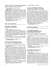
3. SYSTEMCLICK FRAMEWORK For iterative exploration early in the design process, a fast yet performance-indicative way to evaluate implementation variants is required. For this purpose, we have developed the SystemClick framework which generates SystemC performance models from high-level descriptions. SystemClick System Function Model
STA AP
SIFS
RTS
Architecture Model
SystemC Annotated Click model
Codegen SystemClick SystemC model
Simulation
Perf DB
Profiling SystemClick
SIFS
Figure 2: The Y-chart using SystemClick. is based on the Y-chart approach [4] that is commonly used for design space exploration. Application and architecture specifications are independent and kept separately. Only an explicit mapping step leads to an analyzable system implementation. A consecutive profiling and performance analysis step provides feedback for optimizing architecture, application, or mapping. Figure 2 shows the Y-chart for early design space exploration using SystemClick. The different facets of the framework are explained next.
Data frame CTS
Platform resources
Mapping
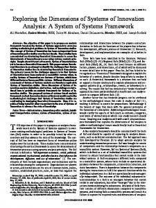
Different frames and the coordination of shared medium access have to follow strict timing rules. Figure 1 shows an atomic frame transfer including an optional medium reservation sequence. In this example, station STA has gained SIFS
Click resource description
Click task graph
Simulation Click
2.2 Protocol Timing Constraints
DIFS & backoff
Application Application
ACK time
Figure 1: Atomic data frame transfer (IEEE 802.11). access to the air and sends a reservation request (RTS frame) to the access point (AP). The AP has to reply after a defined time interval (SIFS period) with a CTS control frame. After reception of CTS, the STA starts the data transfer after another SIFS period. At the end, the AP confirms the successful reception of the data with an ACK control frame, again after a SIFS period. This sequence is atomic. The SIFS periods take care of not being interrupted by others since stations have to wait considerably longer than SIFS after recognizing the free medium in order to transmit on the air (DIFS period and random backoff).
3.1 Application models in Click We describe the application, i.e. the functionality of the WLAN protocol, in an architecture-independent way using Click [5]. Click is a language and framework for describing packet processing applications. In Click, applications are composed from elements linked by directed connections. El-
481
ements describe common computational network operations. Connections specify the flow of packets between elements. Only packets are communicated between elements, state is kept local within elements. Figure 5 (case study) shows the wireless Media Access Control (MAC) layer as an example. Click models capture the concurrency in the application and the dependencies between elements naturally. For verification of the system function, the simulation engine that comes with the framework in combination with bit-true traffic generators can be used. The resulting functionally-correct Click model becomes an input into the mapping step.
RIO
processing resource RCoP
ToEth
PrioSched
RCPU
Classifier
WifiFragment
WifiEncap
frame input
FromEth
RCPU
frame output
… RBUS
3.2 Architecture models in SystemC
RBUS
For SystemClick’s performance models, architectures are abstracted as a set of shared computation and communication resources which arbitrate tasks and consume time. This is reasonable since these aspects alone already have a significant performance impact. A platform architecture is represented by a collection of specialized Click elements. These resource manager (RM) elements specify the properties of a resource, e.g., its type, operating frequency, and scheduling policy. This description is used as input into the mapping step. Resources are implemented in SystemC. To fasten the exploration process, abstract RM elements may be inferred automatically from the Click architecture representation. SystemC, however, enables step-wise refinement, mixed-level simulations, and virtual prototyping.
communication resource
Figure 3: SystemClick representation application-architecture mapping.
of
an
events and must lock the RM it is associated with prior to execution (see implementation in Fig. 4). The RM, in turn, arbitrates its clients according to a given policy and provides architecture information, such as operating frequency. The SystemClick performance database associates each task with costs for a particular resource, e.g., its processing time or communication delay. For indicative results this database is populated with realistic data which can be derived, e.g., from characterizing individual Click elements a) running on embedded processors [14] or b) implemented in hardware [6]. The database (cf. Fig. 2) is accessed at runtime to lookup the costs of each {task, resource} pair. Dynamic access is required due to data and state dependencies of the runtime within a Click element. If necessary, costs can be annotated down to the granularity of basic blocks. A typical Click element has three to five of these tags. To reduce simulation events, processing time accumulated during the execution of a task chain is only synchronized with the SystemC time at points of IO, see Fig. 4.
3.3 Mapping and code generation A Click application graph is partitioned at element boundaries and mapped onto a multi-processor platform manually. To support and ease this task, specialized Click elements are provided, which can be instantiated to guide the code generation process and help to describe mapping specifics. Communication wrappers, for instance, partition a Click graph by cutting and naming a connection. They can be inferred automatically or used explicitly by the designer to partition, refine, and map the communication. To keep concerns separated different source files may be used for application description, platform specification, and mapping annotation. Figure 3 shows a SystemClick application-architecture mapping. Each task chain of the partitioned graph is associated with a computation resource (shown in the upper part of the figure). Communication between tasks on different elements is associated with communication resources (in the lower part). Wrappers (not shown in the figure) extend Click task chains and represent the operating system aspects of a platform. They model the overhead required for event handling, task scheduling, and communication. From the annotated source, SystemClick generates a SystemC model which is compiled together with element libraries for application and architecture using standard tools. Using a performance database, the model can be simulated.
wrapper_push() while in_port.avail() m_delay = 0; rm->lock( id ); in_port.nb_read( p ); update( &m_delay, os_pre ); push( p, &m_delay ); wait( m_delay ); rm->unlock( id );
// sc_thread // block until locked // os overhead anno // run Click task chain // synchronize
Figure 4: Exemplary SystemC facet of a (push) wrapper, which is triggered by an IO event.
3.5 Performance analysis To support the evaluation of a design point’s performance a range of statistics and traces are provided by SystemClick: • Resource Managers trace the execution of tasks and gather data on utilization. They report the overall idle and service time distribution for the resource as well as a per task breakdowns of waiting and service time (min, ave, max). • IO elements gather statistics on their packet flows broken down by packet size or type. They report packet numbers and (min, ave, max) processing time per length/type. • Packets can store the sequence of passed elements over their lifetime. For latency and delay analysis, time stamps for creation and expected deletion can be annotated, e.g., to detect missed deadlines.
3.4 Performance simulation The performance simulation executes Click graphs within a SystemC environment. This way, the architecture platform can be modeled in SystemC as precisely as desired from platform resources with correct communication behavior while the function within a building block is specified by a Click application task graph. Concurrent Click task chains are executed within different SystemC processes provided by wrappers. A wrapper element is triggered by SystemC
482
Table 1: Main processing paths in MAC model.
In addition, a set of Click elements can be used to verify protocol conformance, monitor timing, and control tracing.
4.
A) Outbound transactions. The Ethernet (ETH) header of a host frame is replaced by a WLAN header, a sequence number is added, if necessary the frame is fragmented and encrypted. Also, the transfer rate is selected based on channel properties and the frame is put into a QoS queue. The DCF module, which handles the timed access to the medium, reads the frame from the queue as soon as the link state permits (air is idle for at least a DIFS period, no pending retransmission, contention won). Finally, the duration field is set, FCS appended, and the frame is sent to the PHY layer. B) Inbound transactions. Inbound wireless frames are received and forwarded to the link layer. The link layer checks the CRC, updates the NAV timer, discards frames addressed to other stations, and classifies frames into data, control, and management. Data frames are forwarded to the transaction layer, which separates them by QoS class, removes duplicates from the stream, decrypts and reassembles fragments into packets if necessary, and replaces the WLAN header by an ETH header. C) Outbound acknowledge. Unicast data frames accepted by the MAC initiate the generation of an acknowledge control frame. As soon as a SIFS period passed, the frame is pushed into the regular processing path for outbound transactions (see path A). In the model, acknowledges are always transmitted with the same rate as the data frame. D) Inbound acknowledge. Inbound acknowledges follow the same processing path as in case B until they are classified and forwarded to the DCF. Here retry and back-off counters are reset if the link was expecting the acknowledge. There is a timeout for not received ACK frames. E) Outbound RTS/CTS. If an outbound frame is larger than a threshold (SetRTS) the generation of an outbound RTS frame is triggered as soon as the frame is read by the DCF element (cf. case A). Generation of CTS frames is triggered by reception of RTS. Similar to outbound acknowledges, RTS and CTS frames just follow the regular processing path of case A, after DIFS or SIFS time, respectively. F) Inbound RTS/CTS. Inbound RTS and CTS frames travel this processing path to the DCF. An RTS triggers the generation of the associated CTS (cf. path E). A received CTS frame triggers the transmission of an outbound transaction after SIFS time. G) Outbound management frames. Outbound management frames follow for the most part the path of outbound transactions (path A). Here, the generation of selected frames, e.g. ProbeRequest, is triggered by the host. H) Inbound management frames. These frames travel up to the transaction layer similar to inbound transactions (path B). They are classified and either handled directly or forwarded to the host. Received beacons, e.g., are fed into BeaconScanner/Tracker elements to monitor and update network state.
IEEE 802.11 A/B/G/E CASE STUDY
4.1 Media Access Control (MAC) Click model The model focusses on the full MAC layer function as specified by the 802.11 a/b/g standard and adds the QoS capabilities of 11e. Figure 5 shows a station MAC. Processing paths through the model that we refer to in the results section are listed in Table 1. ACK/ DCF chain busy CTS scheduled packet
Medium busy
WepEncap
WifiSeq
WifiFragment
1
2
Queue 3
Chain busy
rate selection
3
2
DCF
1 0
PaintSwitch
WepEncap
Queue 3
Chain busy
rate selection
3
2
DCF
1 0
WepEncap
WifiSeq
ACK/ DCF chain busy CTS scheduled packet
Medium busy 2
Queue 3
Chain busy
Paint(3)
rate selection
3
2
DCF
1
Queue 3
Chain busy
rate selection
3
PHY /Physical AIR Channel
WepEncap
WifiSeq
ACK/ DCF chain busy CTS scheduled packet
Medium busy 2
SetCRC32
SetDuration
0 1
…
WifiFragment
2
DCF
1
ProbeRequester
Carrier Sense
Scanner & Tracker
PrioSched Tee Beacons & Probe responses
Classifier
…
Ack/Cts
RTS
UpdateNAV
Classifier
control
managment
CheckCRC32
Classifier
GenAck
data
unicast data
BC-Filter
PaintSwitch
WifiDupeFilter WifiDupeFilter WifiDupeFilter WifiDupeFilter
WiffiDefrag WiffiDefrag
WepDecap WepDecap WepDecap WepDecap
WiffiDefrag WiffiDefrag
WiffiDecap WiffiDecap
WiffiDecap WiffiDecap
Other Mgmt frames
GenCTS
HostEtherFilter
System--on on--Chip Core / Host System
ACK/ DCF chain busy CTS scheduled packet
Medium busy 2
1
WifiFragment
SetRTS
ProbeTxRate
WifiEncap
WifiSeq
WifiFragment
1
busy
multicast data
Data Link Layer
Transaction Layer
Figure 5: Click model of a wLAN 802.11 a/b/g station with service differentiation (11e). Not all management processing paths are shown.
Table 2: Processing budget on a 400 MHz system.
4.2 MAC time budgets
Group
WLAN protocols define firm deadlines for transactions on the air, see Section 2.2. Most relevant for the MAC time budget is the timing for responding to a received frame. A typical SIFS time is 16 µs as defined in IEEE 802.11. Inbound frame
Go signal Frame context Frame data
SIFS = 16µs
Outbound response
12µs
2µs
2µs
RX PHY
MAC
RF
Description Signals whether a transmission will follow Context info (length, STA address) required WLAN header and payload required
Budget [µs] [cycles] 2
800
16
6400
20
8000
enabled. After initial authentication and association, every station is saturated with IP-Packets in IMix [1] distribution for transmission. The stations communicate with the AP, whereas the AP sends packets to STA0. The air element gets complete frames with their transfer rates and generates the corresponding transmission delay and half-duplex/busy behavior of the MAC/PHY interface.
16µs Context 20µs Frame Data
Figure 6: MAC time budget for response frames. It specifies the interval between a received frame and its response. Since SIFS is defined on the air, the physical layer (PHY) receive (Rx) and transmit (Tx) processing delays are included in the interval and must be subtracted. Figure 6 shows this in detail. In the Figure, the last byte of the inbound frame is given to the MAC by the Rx PHY only after 12 µs. The CRC can be calculated and the MAC processing starts. For the response frame transmission, the Tx PHY requires the frame data and context after different setup times, as specified in Table 2. For the analysis in this paper, we focus on the frame context deadline. In order to be met, this deadline requires completion of the full protocol processing.
4.4 Results of single-core mapping In the following, we will evaluate platforms (defined by hardware allocation, mapping, software implementation) with respect to achievable network throughput, response time to frame receptions, and resource utilization. The single-core setup in this section maps the full system model for a station as shown in Fig. 5 to a single CPU resource (MIPS M4K CPU at 400MHz). This means, the complete functionality is implemented in software. Following the flow of packets through the MAC along the different processing paths we first characterize the individual processing functions for the performance database using our code generator CRACC [14] with instruction set simu-
4.3 Network setup The network setup comprises two WLAN stations (STA0 and STA1) and an access point (AP) with WEP security
483
scheduling could be modified. Large Click elements can be partitioned to reduce worst-case resource blocking time. In addition, the run-to-completion semantics of Click could be changed to preemptive/prioritized scheduling at the expense of extra overhead. This is a serious change of the underlying model of computation and will thus not be followed in this paper. Second, resource allocation and mapping can be modified so that interference is reduced. Since WLAN shows significant data parallelism the partition onto several resources does not cause data coherency problems as known from general MP-SOCs. In the following we will focus on evaluating a different resource allocation and mapping, which can also be beneficial from a power perspective. The results of the preceding subsection indicate that it will be beneficial to either allocate different processing resources to receive and transmit paths or mapping time critical elements to a separate resource. Figure 8 shows the results for the latter option in terms of a response-time histogram. Mapping the critical link layer (cf. Fig. 5) onto an extra processor leads to reduced response times. There was even slack that we applied to reduce the processing speed. For the same throughput, the non-realtime CPU runs at 150 MHz, while the real-time CPU requires about 200 MHz.
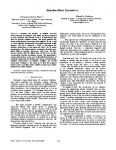
lators and the Click MAC model. As an indication of the processing complexity Figure 7 summarizes the instruction counts for the different paths assuming accelerators for CRC and security. The results show the handling of management 3500 Outbound
Inbound
3000 Max 1498 Byte Typ 550 Byte IMix 330 Byte Min 36 Byte
2500 2000 1500 1000 500 0 A
B
C
Outbound Data
Inbound Data
Outbound Acknowledge
Data frames
D
E
F
Inbound Outbound RTS / Inbound RTS/ Acknowledge Inbound CTS Outbound CTS Control frames
G
H
Generate Beacon
Receive Beacon
Management frames
Figure 7: Single packet icounts per processing path. frames to be the most compute-intense processing paths. However, these frames are processed relatively infrequently compared to data and control frames. Of the more frequent data and control frames, the transmission of data frames in outbound direction is the most instruction consuming case. Achievable Throughput. Using the most instruction consuming path, we perform a worst case analysis assuming that data frames are sent out back-to-back. Since most of the protocol processing happens on a per packet basis, we expect a throughput dependency on the packet size. We observe a throughput ranging from 44 Mb/s to 638 Mb/s. Considering inter frame gaps and protocol overhead on the air this is sufficient for all investigated standards. Resource utilization. As indicated by the throughput analysis: A single MIPS 4k processor running at 400MHz is underutilized. Even if we consider the crypto function in software for the simulation, the processor is seldom used beyond 20% while reaching saturation of the medium. STA1 which only transmits packets has a load of 12%, STA0 which also receives frames has 19%, and the AP which has to process three traffic streams plus additional management functions has 27%. Largest contributors are the WEP implementation in software and the rate selection algorithm. Response time. As mentioned before, most critical are inter-frame gaps for control sequences like RTS/CTS and ACK. Having the full station functionality mapped onto a single core, we recognize that certain transmission deadlines due to responses to received frames cannot be met. Caused by the run-to-completion model of Click, a preceding processing chain of Click elements can block the processor regardless of the priority of sending a response frame. Some cases overemphasize this fact since we have moved encryption processing to software, leading to large monolithic elements. Encryption alone can easily grow beyond 200µs. Figure 8 (single-core) shows a histogram of the results. In detail, response times for the AP range from 6 to 303µs for acknowledges (ACK) with the majority between 40 and 66µs, but 3.3% above 100µs. Similarly, worst-case response times for CTS and DATA are 233 and 114µs respectively.
10000
Single-core ACK
Frame Context Deadline
Single-Core CTS Single-core DATA
Occurrences
1000
Refined ACK Refined CTS Refined DATA
100
10
1 0
20
40
60
80
> 100
Response Time [us]
Figure 8: Response time distribution for the single CPU (400MHz) and refined dual CPU (150/200MHz) mappings.
4.6 Discussion The results using per-element profiling annotations indicate the feasibility of implementing 802.11 MAC functions including the time-critical control frame processing fully in software. Based on the case study, we recognize: • The functional correct simulation increases the confidence in quantitative comparisons of design alternatives. In SystemClick, we can use realistic network setups with real traffic and functional protocol descriptions. • The component-based modeling in Click proved to be flexible and fast for applying modifications on application, architecture and mapping on the granularity of elements. • During the case study, most of the effort was spent on the verification of system functions with modified timings and resource mappings. The tracing capabilities of SystemClick have been useful for understanding the interference of protocol function and resource timing. • The generation of simulation models in combination with CRACC-based profiling [14] and the performance database enabled the fast evaluation of design points.
4.5 Results of refined mapping The problem of missed transmission deadlines of the single-core solution can be addressed by different approaches. First, the granularity of Click tasks and their
484
5.
RELATED WORK
models enable fast yet meaningful assessments of mapping and implementation alternatives for the functionality, such that response time and resource usage can be optimized.
Modeling languages. SDL characterizes communication protocols by control sequences and actions. The 802.11a wireless standard includes an SDL description, which is used in [7] for network analysis. The language focuses on the control flow of an application. Dataflow and computation as required for functional correctness are not first class citizens, see [3]. Attempts that use SDL for performance analysis note the lack of time-related features to express aspects, such as timeouts, time-dependent enablers, or timing constraints imposed by the environment. UML provides structure and describes dependencies between elements, but lacks formal semantics. The use of UML for the design of embedded realtime systems is still a vivid research area [8]. P¨ arssinen [11] describes a UML profile for communication protocols. ESL for wireless MAC designs. There is much work on generating implementations (in hard- and software) from high-level descriptions, such as SDL, e.g., in [3, 10, 15]. The results indicate a lack of implementation efficiency and report significant overhead and restrictions; [10], for instance, reports required clock frequencies of 1 GHz for the resulting implementation after optimizations. Frameworks. StepNP/MultiFlex [12] is a framework for a network processor platform with hardware multi-threading that can use Click as application description. Artemis [13] is targeted at media processing applications and based on Kahn process networks. The commercial CoFluent is similar to [13] and targets platforms with VxWorks processing elements. For the performance evaluation, the OS aspect is abstracted to latency and explicit scheduling strategy [9] similar to SystemClick, while the application code is represented by traces. Both frameworks do not provide a feedback path from architecture timing model to functional model systems, whereas in SystemClick architecture timing can impact the system’s function. Metropolis [2] is a general framework where arbitrary models of computation can be expressed. Its generality, however, makes modeling more complex and less intuitive than by restricting the designer to one consistent application-specific representation. The work in [16] and the references therein describe the stateof-the-art of platform modeling in SystemC. Components can be represented at transaction and RT levels, and programmable parts can be abstracted up to instruction set simulators. The simulation of several architecture building blocks at these levels is too complex to be used for early design space exploration.
6.
Acknowledgments This work has been supported in parts by the Bavarian government (SmartFlow) and the European Union (Omega). We thank C. Teerapat (U Paderborn) for his contributions to the characterization of the WLAN library.
7. REFERENCES
[1] Agilent Technologies. JTC 003: mixed packet size throughput. The Journal of Internet Test Methodologies, pages 16–18, Sept. 2004. [2] F. Balarin, Y. Watanabe, H. Hsieh, et al. Metropolis: an integrated electronic system design environment. IEEE Computer, 36(4):45–52, Apr. 2003. [3] M. Hannikainen, J. Knuutila, T. Hamalainen, and J. Saarinen. Using SDL for implementing a wireless medium access control protocol. In ISMSE, 2000. [4] B. Kienhuis, E. Deprettere, K. Vissers, and P. van der Wolf. An approach for quantitative analysis of application-specific dataflow architectures. In 11th ASAP, pages 338–349, July 1997. [5] E. Kohler et al. The Click modular router. ACM Trans. on Computer Systems, 18(3), Aug. 2000. [6] C. Kulkarni, G. Brebner, and G. Schelle. Mapping a domain specific language to a platform FPGA. In 41st Design Automation Conference, pages 924–927, 2004. [7] P. Latkoski, T. Janevski, and B. Popovski. Modelling and simulation of IEEE 802.11a wireless local area networks using SDL. In MELECON, 2006. [8] L. Lavagno, G. Martin, and B. Selic, editors. UML for real: design of embedded real-time systems. Kluwer Academic Publishers, Norwell, MA, USA, 2003. [9] R. Le Moigne, O. Pasquier, and J.-P. Calvez. A generic RTOS model for real-time systems simulation with SystemC. In Design, Automation and Test in Europe (DATE), volume 3, pages 82–87, 2004. [10] G. Panic, D. Dietterle, et al. A system-on-chip implementation of the IEEE 802.11a MAC layer. In Euromicro DSD, pages 319–324, 2003. [11] J. Parssinen, N. von Knorring, J. Heinonen, and M. Turunen. UML for protocol engineering-extensions and experiences. In 33rd TOOLS, 2000. [12] P. Paulin et al. Parallel programming models for a multiprocessor SoC platform applied to networking and multimedia. IEEE Trans. on VLSI, 14(7), 2006. [13] A. Pimentel, C. Erbas, and S. Polstra. A systematic approach to exploring embedded system architectures at multiple abstraction levels. IEEE Transactions on Computers, 55(2):99–112, 2006. [14] C. Sauer, M. Gries, and S. Sonntag. Modular domain-specific implementation and exploration framework for embedded SW platforms. In DAC, 2005. [15] M. Varsamou et al. From protocol models to their implementation: a versatile testing methodology. IEEE Design & Test of Computers, 21(5), 2004. [16] A. Wieferink, T. Kogel, R. Leupers, et al. A system level processor/communication co-exploration methodology for multi-processor system-on-chip platforms. In DATE, Apr. 2004.
CONCLUSION
We have presented the SystemClick ESL design framework that is tailored to the early design space exploration of WLAN stations and networks. The combination of performance modeling and functional correctness enables the quantitative assessment of implementation alternatives for timing critical protocols. Sensitive design parameters, such as the arbitration of shared resources and granularity of processing kernels, are exposed to the designer. The functional description follows the dataflow driven Click representation known from efficient software routers. The integration with SystemC finally allows the reuse of simulation and analysis, as well as refinement infrastructure. As a result, we have shown in a case study looking at stations of a IEEE 802.11 a/b/g/e network how domain-specific
485