Systems integration of a mixed fibre detection process in raw yarn packages by computer vision J. Silvestre UPV Pl. Ferr. Car. 2. Alcoi 03801
[email protected]
R. Pérez UPV Pl. Ferr. Car. 2. Alcoi 03801
[email protected]
Abstract New automation technologies are introducing important changes in company production organization in all sectors, and particularly, in yarn textile factories. As a result of these changes, the product moves automatically from the point where production begins to the point where it is packed, without human intervention. Thus, the generation of any flaw in the product is not detected in any case, and therefore, the defective product will be delivered to the client, which could represent a high cost for companies. In this paper an automated system is presented for flaw detection in yarn packages.
1. Introduction New automation technologies are introducing important changes in the organization of production for companies in all sectors, including manufacturing. In the textile sector, and particularly in the manufacture of yarns, the necessity to improve the competitiveness of European companies is leading to a high level of automation. As a result of these changes, the yarn packages move automatically from the point where production starts to the point where it is packed without any human intervention, which implies an important saving in production costs. Nevertheless, operating in this form, the generation of any flaw in the product is not detected in any case due to the absence of manual contact with the product, and therefore, if defective products occur, they will be delivered to the client. Computer Vision is being applied to a wide range of industrial sectors and applications [1]. In the textile sector it could be applied to the inspection process or to the final quality inspection [2], the fabric inspection being the sector where there is more works [3]. Although there are some papers and products applied to the control of quality of yarn packages in spinning plants [4], these systems are not commercially used. In our opinion, the main reason is that the systems developed can’t be integrated in the process chain. In yarn packages, there exist different types of flaws,
J. Muñoz AITEX Pl. E. Sala. Alcoi 03801
[email protected]
with different impacts on production and on the claims that the clients could make to the company. In this paper, the detection of the first of these flaws is considered; the appearance of mixed fibres. In the following section the changes that are taking place at the present time in the production processes of yarns are described along with the flaws in the packages that could be produced. In the last section the developed system and the obtained results are described.
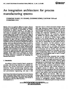
2. Manufacturing Process 2.1. Spinning plants The transformation process in a spinning plant goes from correctly mixing the fibres, to the production of the thread and its winding in the final package. It includes several steps, which are: Unifloc, Shipper, Quarters of mixture/blend Strawberry, Deposit unimix, Carding, drawing frame, spinning and finally packing and labelling of the packages. In all these processes, traditionally it has been necessary for the workers to handle unfinished products, so they can take them to the following stage of the process. This meant that during these operations of handling of the product, there were different points where the worker could perceive flaws in the product, and then they could withdrawn them from the production chain.
Figure 1. Extraction Process
automation in this mixing process, there are cases where a package is made with fibre from a different manufacturer. When this thread is used in the manufacture of a product and it is finished it by dyeing or printing, since the properties of absorption of the different fibre producers could be very different, the
Figure 2. Automation palletising. Currently, given the high degree of automation that is taking place in spinning plants, all these processes are automated. For example, the extraction process of the yarn packages from the spinning machine, weighing, labelling and packing is done totally automatically by a robot machine. In fig. 1 we can see how the packages are taken out of the spinning machine and are put on hangers and then carried by a conveyor belt in the ceiling to the packing system. In fig. 2 how the packages are deposited by the system on conveyor belts (2.a), then are labelled (2.b) and then carried (2.c) to the weighing and packing system (2.d) is shown. Therefore, any flaw produced in the yarn package is not detected, and so, the product will be given to the client, with the claims and economic charges that this could produce. 2.2. Flaw catalogue There are two kinds of yarn spinning that produce different flaw catalogues, and these have an incidence and different impact based on the use that the client is going to make of the product 2.2.1. Raw yarn spinning. In raw yarn spinning, the packages with the correct fibre percentage of mixtures are generated according to the type of fibre and its manufacturer. Despite
Figure 3. Fibber mixture
Figure 4. Contamination product will be flawed which could cause its return to the producer and the loss of thousands of meters. In fig 3 it is possible to appreciate packages exposed to natural or incandescent light (top), and the same package using ultraviolet (UV) light (bottom) with fibre mixture. Another important flaw that has to be detected is the appearance of contamination of other fibres in the package. When this contamination is serious, it is possible to see small parts of other fibres on both sides of the packages. These cases also represent serious problem for companies. In fig. 4 there is a yarn row with contamination. 2.2.2. Coloured yarn spinning Colour yarn spinning presents a similar problem, although with different causes. In these types of yarns the mixing process and homogenization of the percentage of each of the fibres with the suitable colour has a fundamental importance. Nevertheless, in this process deficiencies could mean that the homogeneity of the consignment could be irregular. In fig. 5 it is possible see packages with colour differences very difficult to appreciate (left and center), even by the human eye. In these cases they could have slight colour differences between the first and last
Figure 5. Colour flaws
packages of a consignment. Nevertheless, in these cases, the appearance of mixtures (right), that could be detected by the same process applied to raw spinning. These are generated as a result of the mixture in the fibre packages with an incorrect colour in the generation of the main package. 2.3. Designed system The objective of the system presented in this paper is to detect the existence of mixed fibres in raw yarn packages, because this flaw is the most common and damaging for this type of industry. For the detection of these, a darkroom with front UV light illumination is used to activate the fluorescence of fibres detecting in this way the different fluorescence that is produced by different fibres according to their composition. It is the same method used for human inspection and has been the one that gives the best experimental results after testing other kinds of light with different wavelengths. The system is formed by a firewire colour camera (Bayer Pattern colour) [3], which provides enough capture speed and colour information quality for the application that has been developed. In addition, this allows the processing of several machines with the same processing system. The speed of the packages on the conveyor belt is about 4.5 meters per minute, with the packages having a minimum distance of 70 cm between each one. This provides a capture rate below 6.5 packages per minute, meaning we have more than 9 seconds for each package. Therefore, although the computational cost of the algorithm is elevated, the choice of the hardware allows us to process on the same computer more than one machine, optimizing therefore the use of this resource. The acquisition system is synchronized with the textile machinery through a PLC which provides the necessary signals to the machine for the operation with the control system which orders the acquisition, processing and expulsion of the defective elements or the packing of correct ones. 2.4. Developed Algorithm The algorithm is divided into the following stages: i) colour auto-calibration of the camera capture parameters, ii) Detection of the object in the scene, iii) flat conversion RGB to the colour planes used by the
Figure 6. HSV channels
algorithm, iv) contrast enhancement, v) circular profile calculation, vi) profile analysis for the detection of mixtures. i) Due to the different characteristics of the reflection of the UV light that fibres have, it is better to use different parameters in the camera configuration to obtain the correct image acquisition; changing shutter, brightness, exposure, gain, etc. In this stage there are two possible solutions, based on the type of installation. In spinning plants with an automated transport system, it communicates with the control PC, to know the type of fibre of the package to capture, and thus to arm the camera for a single frame grab with the correct parameters. In other factories, where this information can’t be obtained, for example in those where the installation is made directly in the winding machine, it is necessary to adjust these parameters automatically taking more than one image capture. The algorithm needs to make some captures to fit the capture parameters until the image has correct colour and luminance parameters. Although this could represent an excessive latency, the low capture rate needed allows it. In addition, this adjusting will be only executed generally in the first package after a consignment change, since the following camera configuration parameters will also be valid. Moreover practice show us that normally the system only needs 1 grab to make the parameter adjustment, plus the correct grab. ii) For the object detection in the image, the yarn package, different algorithms have been tested, from images segmentation using colour information, to flood fill type algorithm. Nevertheless, despite the good results obtained in most of the images, these algorithms do not work correctly in all types of fibres and could introduce errors with very visible mixtures in the packages or when there are threads adhered to the package. The best results have been obtained by analysing a horizontal and vertical profile of the raw image. Knowing the edges, and assuming the circular form of the package and an always uniform centre, it is possible to segment the package from the rest of the image. To do this correctly, the camera needs to acquire the image at its most perpendicular to the yarn spinning to avoid ellipse deformations that need correction in the algorithm. iii) Testing different colour planes, it has been demonstrated that better results are obtained working in the HSV space colour, and then at this stage, we transform the original RGB image into a HSV one. iv) With each of the HSV channels, a maximum contrast enhancement algorithm is used in the yarn package area to increase the differences and permit a better detection even with very similar mixes of fibres. In fig. 6 there is a yarn row with a mixture shown in the HSV channels after the contrast enhancement algorithm.
v) To detect the presence of a ring in the yarn package, due to a mixed fibre, a circular profile is obtained. To do this, a circle is adjusted to the inner and outer edges of the package. Next, and with subpixel resolution accuracy, a profiling between the inner and outer adjusted circles is made using a resolution of 1 degree. This process is done in each of the planes of the HSV space, obtaining three radial profiles. In some cases, the mixes are detectable in all three planes, but some of the mixtures can only be detected in one of the planes, meaning the three radial profiles need to be analyzed to assure detection. vi) The profile analysis for the detection of mixtures is based on the search for discontinuities in this profile.
In a yarn package without any mixture, the profile of each channel is a straight line with rounded ends due to the shadow edges of the package. In a yarn package with flaws, this profile has a lower or higher peak. To do this, firstly, the best fit line to the profile and the standard deviation are calculated over the inner portion of the yarn package, avoiding the edges. This doesn’t create a problem, because the possible mixtures always appear in this part, including a possible inner or outer one. This process is done separately over each channel, because each one has a different response. Later, a singularities search process over the entire profile is done, marking each one. With this information, a filter is applied over these points to mix the information over the 3 channels and present a correct result. In fig. 7, there are some mixture samples taken from the working machine (fig. 8).
3. Conclusions The priority for the factories is to detect absolutely all the yarn package with mixtures, so the system parameterization must ensure this. The tests made show a 100% detection of the flawed yarn packages in the factories where it is installed, and very low false alarms; about 0,5%. This low rate false alarm is not important to the factory, because they are removed of the packing line and later revised manually in conjunction with the defective ones. The defective packages are recycled to use the yarn in new packages. This system is currently working in two yarn factories, and being implemented on a third, and there is a prototype for demonstrations in textile shows. It is patent pending also, demonstrating the correct functionality of the system to the yarn industry. Acknowledgement This project was developed collaboration with the UPV. Figure 7. Mixtures captured in real-scenario
AITEX,
in
References [1] [2] [3] [4]
Figure 8. Prototype and real installation
in
[5]
T. S. Newmann, A.K. Jain, A Survey of automated Visual Inspection, Computer Vision and Image Understanding 61(2), pp. 231-262, 1995. J. Muñoz, J. Silvestre, R. Pérez, Estudio para la Aplicación de la Tecnología de Visión Artificial a las PYMEs del sector Textil, AITEX 2002. C. Chan, Fabric Detection by Fourier Analysis, IEEE Transactions on Industry Applications 36(5), pp. 12671276, September/October 2000. N. B. Emery, D. R. Buchanan, Yarn Package Inspection with Computer Vision and Robotics, Textile Research Journal, pp. 605-614, October 1988. B. E. Bayer, Color Imaging Array. US Patent no. 3971065, 1976.