SNUG-2009 San Jose, CA Voted Best Paper 1st Place
World Class Verilog & SystemVerilog Training
SystemVerilog Assertions Design Tricks and SVA Bind Files
Clifford E. Cummings Sunburst Design, Inc.
[email protected] www.sunburst-design.com
ABSTRACT The introduction of SystemVerilog Assertions (SVA) added the ability to perform immediate and concurrent assertions for both design and verification, but some engineers have complained about SVA verbocity or do not understand some of the better methodologies to take full advantage of SVA. This paper documents valuable SystemVerilog Assertion tricks, including: use of long SVA labels, use of the immediate assert command, concise SVA coding styles, use of SVA bind files, and recommended methodologies for using SVA. The concise SVA coding styles detailed in this paper can reduce concurrent SVA coding efforts by 50%-80% over conventional SVA coding techniques.
SNUG 2009 Rev 1.0
1
SystemVerilog Assertions Design Tricks and SVA Bind Files
Table of Contents 1
Introduction............................................................................................................................. 5 1.1 What is an assertion? .......................................................................................................... 5 1.2 What is a property? ............................................................................................................. 5 1.3 Two types of SystemVerilog assertions.............................................................................. 5 2 Long Labels ............................................................................................................................ 6 3 Immediate Assertions ............................................................................................................. 9 3.1 Casting ................................................................................................................................ 9 3.1.1 Static casting ............................................................................................................... 9 3.1.2 Dynamic casting ....................................................................................................... 10 3.1.3 Dynamic casting with immediate assertion .............................................................. 11 3.2 Randomization .................................................................................................................. 11 3.3 Immediate Assertion Summary......................................................................................... 13 4 Concurrent Assertions........................................................................................................... 13 5 Concise Assertion Coding Styles.......................................................................................... 14 5.1 Default clocking blocks and $assertkill ............................................................................ 14 5.2 Macros with arguments..................................................................................................... 15 5.2.1 Simple macro definitions .......................................................................................... 16 5.2.2 Complex macro definitions with arguments ............................................................. 16 5.2.3 SystemVerilog-2009 macros with default arguments............................................... 17 5.3 Measuring the efficiency of macro assertion coding styles .............................................. 18 5.3.1 Synchronous FIFO assertion subset.......................................................................... 18 5.3.2 Separate properties and assertions ............................................................................ 18 5.3.3 Combined properties and assertions ......................................................................... 20 5.3.4 Macros and assertions ............................................................................................... 21 5.4 Assertion coding benchmarks ........................................................................................... 22 6 SVA Bind Files ..................................................................................................................... 24 6.1 A closer look at the bind command .................................................................................. 27 6.2 SystemVerilog bind file use and abuse............................................................................. 29 6.2.1 Binding invisibility and multiple bound modules..................................................... 29 6.2.2 Nested binding is not permitted ................................................................................ 30 6.2.3 complex design structure created through bind commands...................................... 30 7 SVA File Methodologies ...................................................................................................... 31 7.1 Partitioning assertion files ................................................................................................ 31 7.2 Synthesis tool enhancement request ................................................................................. 32 8 Summary & Conclusions ...................................................................................................... 33 9 Acknowledgements............................................................................................................... 33 10 References............................................................................................................................. 34 11 Author & Contact Information.............................................................................................. 34 12 Appendix............................................................................................................................... 36 12.1 Synchronous FIFO assertions ....................................................................................... 36 12.2 Separate property and assertion style............................................................................ 37 12.3 Combined assert property style..................................................................................... 40 12.4 Assertion macro style.................................................................................................... 42
SNUG 2009 Rev 1.0
2
SystemVerilog Assertions Design Tricks and SVA Bind Files
Table of Figures Figure 1 - Monitored output from model with assertion $display command but no label ............. 7 Figure 2 - Waveform display of failing assertion ($display command not visible) ....................... 7 Figure 3 - Monitored output from model with long labeled assertion............................................ 8 Figure 4 - Waveform display of failing assertion (descriptive assertion label is visible)............... 8
Table of Examples Example 1 - Incorrectly coded D-flip-flop model .......................................................................... 6 Example 2 - Assertion with $display command but no label ......................................................... 6 Example 3 - Assertion command with long descriptive label ........................................................ 7 Example 4 - Enumerated valid_e typedef and valid_bit declaration .............................................. 9 Example 5 - Static cast example ..................................................................................................... 9 Example 6 - Dynamic cast - $cast used as a system task.............................................................. 10 Example 7 - Dynamic cast - $cast used as a system function and tested with if-statement ......... 10 Example 8 - Dynamic cast - $cast used as a system function and tested with concise if-statement ............................................................................................................................................... 11 Example 9 - Dynamic cast - $cast used as a system function and tested with an immediate assert ............................................................................................................................................... 11 Example 10 - TestVars class definition ........................................................................................ 12 Example 11 - Illegal use of randomize() method.......................................................................... 12 Example 12 - Void-cast of randomize() method........................................................................... 12 Example 13 - If-test of randomize() method................................................................................. 12 Example 14 - Assertion of randomize() method........................................................................... 13 Example 15 - Simple property assertion....................................................................................... 13 Example 16 - Simple property assertion with property definition details shown......................... 14 Example 17 - Separate property definition with subsequent property assertion .......................... 14 Example 18 - Default clocking block - posedge clk is the assertion sample signal ..................... 15 Example 19 - Reset block with $assertkill and $asserton............................................................. 15 Example 20 - Concise assertion with active clocking block and $assertkill on reset................... 15 Example 21 - Simple macro definition and usage to define a clock oscillator............................. 16 Example 22 - Incomplete assertion macro with commonly used assertion code ......................... 16 Example 23 - Completed assertion macro with argument passed to the macro ........................... 17 Example 24 - Macro with argument used to declare concurrent assertion ................................... 17 Example 25 - SystemVerilog-2009 macro definition - two of three arguments have default values ............................................................................................................................................... 17 Example 26 - SystemVerilog-2009 macro called with non-default arguments............................ 17 Example 27 - FIFO assertion subset declared as separate properties and assertions.................... 20 Example 28 - FIFO assertion subset declared as combined properties and assertions................. 20 Example 29 - FIFO assertion subset declared and asserted using concise macro definitions ...... 21 Example 30 - SystemVerilog assertions wrapped in a module for use as a bind file ................... 24 Example 31 - pLib_fifo assertion file bound to the u1 instance of the fifo1 module with matching signal names.......................................................................................................................... 25 Example 32 - tb1a with fifo1 instantiation and pLib_fifo bind commands using named port connections ........................................................................................................................... 26 Example 33 - The bound pLib_fifo instantiation replaced with an equivalent instantiation........ 26 Example 34 - Binding to a file where the bind-file port names do not match the target module signal names.......................................................................................................................... 28 SNUG 2009 Rev 1.0
3
SystemVerilog Assertions Design Tricks and SVA Bind Files
Example 35 - The bound pLib_fifo instantiation replaced with an equivalent instantiation in the fifo2 module.......................................................................................................................... 28 Example 36 - Non-recommended complex design structure created using a bind command ...... 30 Example 37 - pLib_fifo_ports.sv - Assertion partitioning - ports-only assertions ....................... 32 Example 38 - pLib_fifo_regs.sv - Assertion partitioning - ports and internal registered signals assertions............................................................................................................................... 32 Example 39 - pLib_fifo_sigs.sv - Assertion partitioning - ports and all internal signals assertions ............................................................................................................................................... 32
SNUG 2009 Rev 1.0
4
SystemVerilog Assertions Design Tricks and SVA Bind Files
1 Introduction As I have watched the enthusiasm and growing interest in SystemVerilog Assertions (SVA) over the past five years, I have witnessed multiple design teams who have taken SVA training, embraced the potential for rapid design and debug using SVA, but who have later largely abandoned the use of SVA due to the perceived verbose nature regarding the creation and implementation of SystemVerilog assertions. Over the past three years, I have made it a priority to develop SVA usage techniques that even design engineers would adopt. This paper details some SVA methodology techniques that I highly recommend, especially for design engineers. There are some simple tricks that every design engineer should know to facilitate the usage of SystemVerilog Assertions. Although this paper is not intended to be a comprehensive tutorial on SystemVerilog Assertions, it is worthwhile to give a simplified definition of a property and the concurrent assertion of a property. 1.1
What is an assertion?
An assertion is basically a "statement of fact" or "claim of truth" made about a design by a design or verification engineer. An engineer will assert or "claim" that certain conditions are always true or never true about a design. If that claim can ever be proven false, then the assertion fails (the "claim" was false). Assertions essentially become active design comments, and one important methodology treats them exactly like active design comments. More on this in Section 2. A trusted colleague and formal analysis expert[1] reports that for formal analysis, describing what should never happen using "not sequence" assertions is even more important than using assertions to describe always true conditions. 1.2
What is a property?
A property is basically a rule that will be asserted (enabled) to passively test a design. The property can be a simple Boolean test regarding conditions that should always hold true about the design, or it can be a sampled sequence of signals that should follow a legal and prescribed protocol. For formal analysis, a property describes the environment of the block under verification, i.e. what is legal behavior of the inputs. 1.3
Two types of SystemVerilog assertions
SystemVerilog has two types of assertions: (1) Immediate assertions (2) Concurrent assertions Immediate assertions execute once and are placed inline with the code. Immediate assertions are not exceptionally useful except in a few places, which are detailed in Section 3. SNUG 2009 Rev 1.0
5
SystemVerilog Assertions Design Tricks and SVA Bind Files
Concurrent assertions are the most valuable and most widely used type of assertion. Concurrent assertions are either placed directly in the RTL code or are bound to an RTL file using the bind command (see Section 6). Concurrent assertions activate properties (rules) that typically sample design signals or sequences of design signals just before each new active clock edge to determine if the design is behaving as it was claimed that it should behave. Engineers have been adding assertions to their designs for years, but they often called them monitors and they were often placed in always blocks to sample at fixed intervals or only when certain signals changed. Regarding formal analysis, immediate assertions are only valid for simulation but concurrent assertions are useful both for formal and simulation.
2 Long Labels Adding labels to concurrent assertions is optional, but highly recommended. The long labels help to debug the assertions in a waveform display. To demonstrate the effectiveness of using long labels when debugging a design, assume that an exceptionally incompetent engineer has coded a very flawed D-flip-flop as shown in Example 1: module dff ( output logic q, input d, clk, rst_n); assign q = d; // This is clearly a mistake!! endmodule Example 1 - Incorrectly coded D-flip-flop model
To this dff module, let's first add a concurrent assertion with no label, but we will include an SVA action block with an error message that will display when the assertion fails, as shown in Example 2. assert property (@(posedge clk) disable iff (!rst_n) (q==$past(d))) else $display("ERROR: q did not follow d"); Example 2 - Assertion with $display command but no label
Using VCS, when the simulation fails, an error message will be displayed to the computer screen as shown on multiple lines of the output as shown in Figure 1. 0ns: 5ns: 10ns: 15ns: 20ns: 25ns: 30ns: SNUG 2009 Rev 1.0
clk=0 clk=1 clk=0 clk=1 clk=0 clk=1 clk=0
rst_n=0 rst_n=0 rst_n=1 rst_n=1 rst_n=1 rst_n=1 rst_n=1
d=1 d=1 d=1 d=1 d=1 d=1 d=0
q=1 q=1 q=1 q=1 q=1 q=1 q=0 6
SystemVerilog Assertions Design Tricks and SVA Bind Files
"sva_ex01.sv", 20: sva_ex01.unnamed$$_1: started at 35ns failed at 35ns Offending '(q == $past(d))' ERROR: q did not follow d 35ns: clk=1 rst_n=1 d=0 q=0 40ns: clk=0 rst_n=1 d=1 q=1 "sva_ex01.sv", 20: sva_ex01.unnamed$$_1: started at 45ns failed at 45ns Offending '(q == $past(d))' ERROR: q did not follow d 45ns: clk=1 rst_n=1 d=1 q=1 ... Figure 1 - Monitored output from model with assertion $display command but no label
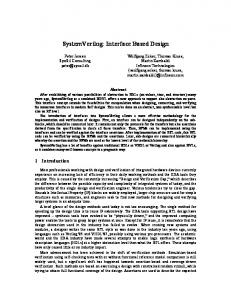
The waveform display for this same simulation is shown in Figure 2.
Figure 2 - Waveform display of failing assertion ($display command not visible)
During simulation, the assertion fails, but when the simulation is viewed in a waveform display, the $display error message is not visible. Only a non-descriptive generic name for the assertion is visible. Engineers looking at the waveform display of the first failing assertion will be unable to identify the problem until they consult the original source code. Now let's add the assertion with long descriptive label shown in Example 3 to the dff source code of Example 1. ERROR_q_did_not_follow_d: assert property (@(posedge clk) disable iff (!rst_n) (q==$past(d))); Example 3 - Assertion command with long descriptive label
When the simulation fails, error messages will be displayed to the computer screen as shown on the output in Figure 3. Note how the label is included in the default error message generated by the assertion. 0ns: 5ns: 10ns: 15ns: 20ns: 25ns: 30ns:
SNUG 2009 Rev 1.0
clk=0 clk=1 clk=0 clk=1 clk=0 clk=1 clk=0
rst_n=0 rst_n=0 rst_n=1 rst_n=1 rst_n=1 rst_n=1 rst_n=1
d=1 d=1 d=1 d=1 d=1 d=1 d=0
q=1 q=1 q=1 q=1 q=1 q=1 q=0
7
SystemVerilog Assertions Design Tricks and SVA Bind Files
"sva_ex01.sv", 17: sva_ex01.ERROR_q_did_not_follow_d: started at 35ns failed at 35ns Offending '(q == $past(d))' 35ns: clk=1 rst_n=1 d=0 q=0 40ns: clk=0 rst_n=1 d=1 q=1 "sva_ex01.sv", 17: sva_ex01.ERROR_q_did_not_follow_d: started at 45ns failed at 45ns Offending '(q == $past(d))' 45ns: clk=1 rst_n=1 d=1 q=1 ... Figure 3 - Monitored output from model with long labeled assertion
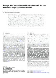
The waveform display for this same simulation is shown in Figure 4.
Figure 4 - Waveform display of failing assertion (descriptive assertion label is visible)
During simulation, the assertion code of Example 3 would fail, but now when the simulation results are viewed in a waveform display, the long and descriptive label name will be visible to document the failing behavior of the labeled assertion. Contrasting the assertion code of Example 2 with the assertion code of Example 3, both would fail and report errors, but when the simulation results from both assertion styles are viewed in separate waveform displays, the $display error message of Example 2 will not be visible while the long and descriptive label name of Example 3 will be visible to quickly help the engineer identify and debug the problem. Since these long label names are visible in a waveform display, it is also a good idea to use a label naming convention. The naming convention that I use starts each label with "ERROR_" followed by a description of what the error is if the assertion fails. I have watched engineers for the past five years use SVA in their designs and the power-users consistently add long labels to document the intent of the assertions while simultaneously making the intended assertions visible in a waveform display to aid the debugging effort. I tell design engineers to think of the labels as a comment that describes the purpose of the assertion that will show up in the waveform display if the assertion fails. The assertion with label has simultaneously become a monitor with active design comment.
SNUG 2009 Rev 1.0
8
SystemVerilog Assertions Design Tricks and SVA Bind Files
3 Immediate Assertions Immediate assertions as defined in the IEEE Std 1800-2005 are not exceptionally useful in a SystemVerilog design or verification environment, but there are a couple of places where they can be quite useful. 3.1
Casting
There are two forms of casting in SystemVerilog (1) Static-Speed casting, and (2) DynamicSafe casting. In this paper, the terms static-speed casting and static casting will be used interchangeably, while the terms dynamic-safe casting and dynamic casting will also be used interchangeably. The SystemVerilog Standardization Committee introduced the two distinct styles of casting because vendors explained that the type and boundary checking required by dynamic casting could seriously degrade simulation performance. By allowing two forms of casting, engineers that were interested in higher performance simulations and who were also confident that all of the casting in their code was type and boundary-safe could choose to use the faster static casting, while engineers concerned about type and boundary checks could use the slower dynamic casting. Consider the type definition of the valid_e enumerated type, and the declaration of the valid_bit, declared to be of the valid_e enumerated type as shown in Example 4 typedef enum {good, bad} valid_e; valid_e valid_bit; Example 4 - Enumerated valid_e typedef and valid_bit declaration
In SystemVerilog, enumerated types are a strongly-typed type when used as the target of an assignment so it is illegal to make direct integer assignments to an enumerated variable. 3.1.1
Static casting
The SystemVerilog static cast uses a data type to cast an argument enclosed within parentheses to the new data type and then assigns the cast-modified value to a target of the same or compatible type. In Example 5. The there are two legal and one illegal static cast assignments. initial begin valid_bit = valid_e'(0); $display("static cast: 0->valid_bit=%0d", valid_bit, " name=%s", valid_bit.name()); valid_bit = valid_e'(1); $display("static cast: 1->valid_bit=%0d", valid_bit, " name=%s", valid_bit.name()); valid_bit = valid_e'(2); // (rptr==0 && wptr==0 && empty==1 && full==0 && cnt==0)); endproperty
FIFO full condition properties: property full_fifo_condition; @(posedge clk) disable iff (!rst_n) (cnt>15 |-> full); endproperty property not_full_fifo_condition; @(posedge clk) disable iff (!rst_n) (cnt !full); endproperty property fifo_should_go_full; @(posedge clk) disable iff (!rst_n) (cnt==15 && write && !read |=> full); endproperty property full_write_full; @(posedge clk) disable iff (!rst_n) (full && write && !read |=> full); endproperty property full_write_wptr_no_change; @(posedge clk) disable iff (!rst_n) (full && write && !read |=> $stable(wptr)); endproperty
Now assert the predefined FIFO properties. Asynchronous reset assertion: ERROR_FIFO_RESET_SHOULD_CAUSE_EMPTY1_FULL0_RPTR0_WPTR0_CNT0: assert property (reset_rptr0_wptr0_empty1_full0_cnt0);
FIFO full condition assertions: ERROR_FIFO_SHOULD_BE_FULL: assert property (full_fifo_condition); ERROR_FIFO_SHOULD_NOT_BE_FULL: assert property (not_full_fifo_condition); ERROR_FIFO_DID_NOT_GO_FULL: assert property (fifo_should_go_full); ERROR_FIFO_FULL__WRITE_CAUSED_FULL_FLAG_TO_CHANGE: assert property (full_write_full); SNUG 2009 Rev 1.0
19
SystemVerilog Assertions Design Tricks and SVA Bind Files
ERROR_FIFO_FULL__WRITE_CAUSED_WPTR_TO_CHANGE: assert property (full_write_wptr_no_change); Example 27 - FIFO assertion subset declared as separate properties and assertions
The declaration and assertion of these properties requires 37 lines of code (blank lines omitted) and 1,225 characters. That is a lot of code and effort to monitor six potential error conditions, which is why design engineers quickly abandon this assertion coding style. 5.3.3
Combined properties and assertions
Another technique frequently shown to engineers in assertion training, is the declaration of asserted properties without separate declaration of named properties. Although this technique does work, the technique is still too verbose for the average design engineer who might intend to construct design-specific assertions. The FIFO assertion subset described in Section 5.3.1 is declared as a set of combined properties and assertions as shown in Example 28 over the next couple of pages. Asynchronous reset assertion: ERROR_FIFO_RESET_SHOULD_CAUSE_EMPTY1_FULL0_RPTR0_WPTR0_CNT0: assert property (@(posedge clk) (!rst_n |-> (rptr==0 && wptr==0 && empty==1 && full==0 && cnt==0)));
FIFO full condition assertions: ERROR_FIFO_SHOULD_BE_FULL: assert property (@(posedge clk) disable iff (!rst_n) (cnt>15 |-> full)); ERROR_FIFO_SHOULD_NOT_BE_FULL: assert property (@(posedge clk) disable iff (!rst_n) (cnt !full)); ERROR_FIFO_DID_NOT_GO_FULL: assert property (@(posedge clk) disable iff (!rst_n) (cnt==15 && write && !read |=> full)); ERROR_FIFO_FULL__WRITE_CAUSED_FULL_FLAG_TO_CHANGE: assert property (@(posedge clk) disable iff (!rst_n) (full && write && !read |=> full)); ERROR_FIFO_FULL__WRITE_CAUSED_WPTR_TO_CHANGE: assert property (@(posedge clk) disable iff (!rst_n) (full && write && !read |=> $stable(wptr))); Example 28 - FIFO assertion subset declared as combined properties and assertions
The declaration and assertion of these properties requires 19 lines of code (blank lines omitted) and 809 characters. Although not as verbose as the separate property declarations and assertions of Section 5.3.2, it is still a lot of code and effort to monitor six potential error conditions, which is why design engineers also quickly abandon this assertion coding style. SNUG 2009 Rev 1.0
20
SystemVerilog Assertions Design Tricks and SVA Bind Files
For most design engineers, these last two assertion coding styles are the only styles that engineers have been taught, so many design engineers abandon adding assertions altogether. 5.3.4
Macros and assertions
As stated earlier in the paper, design engineers frequently avoid writing assertions, because it takes too much code to create the assertions to test even the simplest design features. The technique that I encourage most design engineers to use is to define a couple of simple, yet powerful, macros that can reduce the coding effort required to add assertions to the typical design. The FIFO assertion subset described in Section 5.3.1 is declared using a couple of simple macros as shown in the assertion macro definitions of Example 29. Assertion macro definitions: `define assert_clk(arg) \ assert property (@(posedge clk) disable iff (!rst_n) arg) `define assert_async_rst(arg) \ assert property (@(posedge clk) arg)
Asynchronous reset assertion: ERROR_FIFO_RESET_SHOULD_CAUSE_EMPTY1_FULL0_RPTR0_WPTR0_CNT0: `assert_async_rst(!rst_n |-> (rptr==0 && wptr==0 && empty==1 && full==0 && cnt==0));
FIFO full condition assertions: ERROR_FIFO_SHOULD_BE_FULL: `assert_clk (cnt>15 |-> full); ERROR_FIFO_SHOULD_NOT_BE_FULL: `assert_clk (cnt !full); ERROR_FIFO_DID_NOT_GO_FULL: `assert_clk (cnt==15 && write && !read |=> full); ERROR_FIFO_FULL__WRITE_CAUSED_FULL_FLAG_TO_CHANGE: `assert_clk (full && write && !read |=> full); ERROR_FIFO_FULL__WRITE_CAUSED_WPTR_TO_CHANGE: `assert_clk (full && write && !read |=> $stable(wptr)); Example 29 - FIFO assertion subset declared and asserted using concise macro definitions
The declaration of the macros and use of the assertion-macros requires 17 lines of code (blank lines omitted) and 725 characters. The declaration of the assertions omitting the macro declarations requires 13 lines of code (blank lines omitted) and 568 characters. This is a reasonable effort to monitor six potential FIFO error conditions. This technique permits rapid SNUG 2009 Rev 1.0
21
SystemVerilog Assertions Design Tricks and SVA Bind Files
definition of assertions that offer great value to the design engineer. I have found that design engineers are much more willing to adopt assertion based design techniques when presented with this simple, yet powerful, assertion macro technique. A good way to approach the use of assertion macros is to think of the assertion label as the comment that describes the condition if the assertion fails, thereby documenting the intent of the assertion, followed by the actual assertion test. All of the tedious overhead-code of the assertion has been collected into the macro definition itself. 5.4
Assertion coding benchmarks
So what is the effort required to code a reasonable set of assertions using the three techniques described in the preceding sections? The Appendix in Section 12 includes a set of 13 assertions that could reasonably be applied to a 1-clock synchronous FIFO design. The assertions are coded using the three techniques described in the preceding sections. After coding the assertions using all three techniques, the code volume was measured as the number of lines of code required and characters used to code each set of assertions. The blank lines were omitted from the measurements. The assertion macro definitions were also omitted from the measurements under the assumption that as more macro-assertions are added to a design, the six lines of definition code would eventually become insignificant. Style (blank lines omitted) Property/Assert Property Assert Property Macros
Lines of code 79 40 27
Additional lines of code (%) 193% 48% 0%
Characters 2599 1707 1151
Additional characters (%) 126% 48% 0%
Table 1 - Assertion coding effort
It can be seen from Table 1 that the coding effort required to add one of the traditional assertion coding techniques with assertion-labels required approximately 50%-125% more characters than what was required to add the same assertions using the concise macro definitions. The same assertions were then measured after deleting the labels. The assumption is that the labels represent a minimal set of comments that an engineer should already be adding to the design regarding each corner case tested with an assertion. After omitting the labels, we can accurately measure the effort required to just add assertion tests to this FIFO design. Style (with no labels & blank lines omitted Property/Assert Property Assert Property Macros
Lines of code 66 27 14
Additional lines of code (%) 371% 93% 0%
Characters 2067 1175 593
Additional characters (%) 249% 98% 0%
Table 2 - Assertion coding effort with labels omitted
SNUG 2009 Rev 1.0
22
SystemVerilog Assertions Design Tricks and SVA Bind Files
It can be seen from Table 2 that the coding effort required to add one of the traditional assertion coding techniques required approximately 100%-250% more characters than what was required to add the same assertions using the concise macro definitions. Any of these SVA coding styles work well, but I have found that engineers are much more willing to add assertions to their designs if the effort required to add the assertions is reasonable. The concise macro definitions offer a much more attractive option over traditional SVA coding styles.
SNUG 2009 Rev 1.0
23
SystemVerilog Assertions Design Tricks and SVA Bind Files
6 SVA Bind Files There are times when there is a golden Verilog or VHDL model that cannot be touched. Under these circumstances, business decisions dictate that the model cannot be modified, yet it would be useful to add SVA to the model. How can SVA be added to such models? The answer is to bind an SVA file to the golden model as described in this section. What if you could secretly (or not-so secretly) instantiate a module with SVA into the golden Verilog or VHDL RTL file without disturbing the exiting Verilog or VHDL code. This is the idea behind an SVA bind file. Binding an SVA file to another design is like poking or projecting an instantiation of an SVA module into the unmodified target file. Binding an SVA file to a target file is an out-of-body experience for the target file! The official description of bind files and usage can be found in section 17.15 of the IEEE Std 1800-2005[9]. The examples in the IEEE Standard are somewhat abbreviated and can be difficult to understand, so additional and more complete examples are shown in this section of the paper. Contrasting SystemVerilog bind files to the PSL vunit, the vunit is almost like an external `include statement, where the vunit code is included into the target module without placing the `include into the golden source code. A PSL vunit does not surround the set of included assertions with any type of scope container, such as a module, and does not require any port connections to connect the signals of the vunit to the signals of the target module. The vunit scope container is the target module that it is attached to itself. The signals in the vunit are coded to match the names of the signals in the target module. If a second copy of the vunit assertions is required to connect to a second set of signals in the target module, the vunit must be copied and signal names changed. Unlike the PSL vunit, SVA bind files require that the assertions be wrapped in a module that includes port declarations as shown in Example 30. `define assert_clk(arg) \ ... `define assert_asyn_rst(arg) \ ... module pLib_fifo ( input [7:0] dout, din, input [4:0] cnt, input [3:0] wptr, rptr, input empty, read, full, input write, clk, rst_n); ERROR_FIFO_RESET_SHOULD_CAUSE_EMPTY1_FULL0_RPTR0_WPTR0_CNT0: `assert_async_rst(!rst_n |-> ... ERROR_FIFO_SHOULD_BE_FULL: `assert_clk (cnt>15 |-> full); ... endmodule Example 30 - SystemVerilog assertions wrapped in a module for use as a bind file
SNUG 2009 Rev 1.0
24
SystemVerilog Assertions Design Tricks and SVA Bind Files
The SVA bind file is externally instantiated into the target design module without making any modification to the target module itself. The SVA bind command is used to externally instantiate, or to "bind" the assertion module into the target module. Since the SVA assertions are wrapped in an enclosing module with ports, it creates its own scope and the signal names in the assertions do not have to match the signal names of the target module. The mapping of target signal names to assertion-file signal names happens when the assertion module ports are connected through the bind-instantiation to the target module ports using standard Verilog named port connections (preferred method) or Verilog positional port connections. If the assertion module uses the same signal names as the target module, the bind file port declarations are still required but the bind-instantiation can be done using the SystemVerilog .* implicit port connections[3]. A sample of this type of bind-instantiation is shown in Example 31. module tb1; logic [7:0] dout; logic full, empty; logic write, read, clk, rst_n; logic [7:0] din; ... fifo1 u1 (.*); bind fifo1: u1 pLib_fifo p1 (.*); ... endmodule module fifo1 ( output logic [7:0] dout, output logic full, empty, input logic write, read, clk, rst_n, input logic [7:0] din); logic [7:0] fifomem [0:15]; logic [3:0] wptr, rptr; logic [4:0] cnt; ... endmodule Example 31 - pLib_fifo assertion file bound to the u1 instance of the fifo1 module with matching signal names
Note that the fifo1 module has internal vectors named, wptr, rptr and cnt, and the pLib_fifo module has ports by the same names, but these same vectors are not declared in the tb1 module, because these vectors do not exist in the tb1 module. These vectors only exist in the fifo1 and pLib_fifo modules and since the pLib_fifo module is indirectly instantiated into the fifo1 module through the use of the "bind" mechanism, and does not really exist in the tb1 module, there is no need to make the wptr, rptr and cnt declarations in the tb1 module. If the tb1 module used named port connections instead of the .* implicit port connections as shown in Example 31, the fifo1 instantiation and pLib_fifo bind commands would be expanded as shown in Example 32.
SNUG 2009 Rev 1.0
25
SystemVerilog Assertions Design Tricks and SVA Bind Files
module tb1a; logic [7:0] dout; logic full, empty; logic write, read, clk, rst_n; logic [7:0] din; ... fifo1 u1 (.dout(dout), .full(full), .write(write), .read(read), bind fifo1: u1 pLib_fifo p1 ( .dout(dout), .full(full), .write(write), .read(read), .wptr(wptr), .rptr(rptr), ... endmodule
.din(din), .empty(empty), .clk(clk), .rst_n(rst_n)); .din(din), .empty(empty), .clk(clk), .rst_n(rst_n), .cnt(cnt));
Example 32 - tb1a with fifo1 instantiation and pLib_fifo bind commands using named port connections
Again note that the bound pLib_fifo module references the wptr, rptr and cnt vectors that exist in the fifo1 module but do not exist in the tb1a testbench module. This is an important concept to understand with regards to binding files: that file binding is used to place a copy of the bound module into a different location and not in the file where the bind keyword is used. If it were permitted to instantiate the pLib_fifo SVA module directly into the fifo1 module, we could delete the bind command from the tb1 module and directly instantiate the pLib_fifo module into the fifo1 module, as shown in Example 33. module tb1; ... fifo1 u1 (.*); bind fifo1: u1 pLib_fifo p1 (.*); ... endmodule
Replace indirect binding
module fifo1 ( with actual instantiation output logic [7:0] dout, output logic full, empty, input logic write, read, clk, rst_n, input logic [7:0] din); logic [7:0] fifomem [0:15]; logic [3:0] wptr, rptr; logic [4:0] cnt; ... pLib_fifo p1 (.*); ... endmodule
Example 33 - The bound pLib_fifo instantiation replaced with an equivalent instantiation
SNUG 2009 Rev 1.0
26
SystemVerilog Assertions Design Tricks and SVA Bind Files
6.1
A closer look at the bind command
Let's examine the bind command from Example 31 in greater detail. A second form of the bind command is discussed later in this section. bind
fifo1: u1
pLib_fifo p1
(.*);
In the first box: The command uses the bind keyword and is followed by the target module name (fifo1) that we are binding to. This example also shows the optional argument that allows us to only bind to the u1 instance2 of the fifo1 module (: u1) and not to every instance of the fifo1 module, which would happen if we had omitted the : u1 argument. In the second box: Now we need to indicate which file is to be bound into the target module. The name of the file to be bound is the assertion file (pLib_fifo) and when the assertion file is bound into the target module, it shall have the instance name p1, and the instantiation shows that all of the ports on the bound assertion file are connected to signals with the same name ( (.*); ) in the target module. Note that if the assertion file had been instantiated directly into the target module, the instantiation text would be exactly all of the text in the second box. There is a second legal form of the bind command that allows binding to individual instances in a design without naming the instantiated module. This is done by dropping the module_name: from the first box shown above. To rewrite the bind command used in Example 31, simply reference the instance name with the bind command in the first box as shown below. This second form of the bind command is currently better supported by most tools to bind a file to just one instance of a module. bind u1
pLib_fifo p1
(.*);
A frequently asked question about the bind command as shown above is, why is it necessary to include the instance name p1? Part of the answer to this question is that all instantiated modules must have an instance name attached to the instantiation. The instance name allows another module to hierarchically reference signals in the p1-scope. A second reason to have the instance name p1 is, suppose the target module fifo1 actually is a dual fifo module and we would like to attach two copies of the exact same pLib_fifo assertions to each fifo block in the module. If the assertion module uses different signal names than the target module, the bind file port declarations are still required and the bind-instantiation is done using named (or positional) port connections for all ports not connected by using .* implicit ports, as shown in Example 34. 2
At the time that this paper was published, not all SystemVerilog implementations permitted binding to the optional single instance of the target module, but Questa does have this feature implemented SNUG 2009 Rev 1.0
27
SystemVerilog Assertions Design Tricks and SVA Bind Files
module tb2; ... fifo2 u1 (.*); bind fifo2: u1 pLib_fifo1 p1 (.wptr(qptr), .rptr(iptr), .cnt(word_counter), .*); ... endmodule module fifo2 ( output logic [7:0] dout, output logic full, empty, input logic write, read, clk, rst_n, input logic [7:0] din); logic [7:0] fifomem [0:15]; logic [3:0] qptr, iptr; // new names for wptr and rptr logic [4:0] word_counter; // new name for cnt ... endmodule Example 34 - Binding to a file where the bind-file port names do not match the target module signal names
In Example 34, the assertion bind-file has ports named wptr, rptr and cnt, that need to be connected to the fifo2 qptr, iptr and word_count buses respectively. Since the names do not match, the bind command connects these pLib_fifo1 ports to the corresponding fifo2 ports by name and makes all other connections using .* implicit port connections. If we were permitted to instantiate the pLib_fifo1 assertion file directly into the fifo2 module, we would need to use the exact same named port connections for non-matching signals and .* for all remaining signals, as shown in Example 35. module tb2; ... fifo2 u1 (.*); bind fifo2: u1 pLib_fifo1 p1 (.wptr(qptr), .rptr(iptr), .cnt(word_counter), .*); ... endmodule module fifo2 ( output logic [7:0] dout, output logic full, empty, input logic write, read, clk, rst_n, input logic [7:0] din); logic [7:0] fifomem [0:15]; logic [3:0] qptr, iptr, // new names for wptr and rptr logic [4:0] word_counter; // new name for cnt ... pLib_fifo1 p1 (.wptr(qptr), .rptr(iptr), .cnt(word_counter), .*); ... endmodule Example 35 - The bound pLib_fifo instantiation replaced with an equivalent instantiation in the fifo2 module
SNUG 2009 Rev 1.0
28
SystemVerilog Assertions Design Tricks and SVA Bind Files
Binding assertions to a golden Verilog RTL model allows design and verification engineers to still take advantage of assertion based design techniques without the requirement to modify a golden Verilog model. Although not defined in the SystemVerilog IEEE Std 1800-2005, many vendors also allow engineers working in a mixed Verilog & VHDL design and verification environment to bind SVA files to a golden VHDL model. 6.2
SystemVerilog bind file use and abuse
The bind command was originally intended to be used to add assertions to a design without modifying the original RTL code. The use has been further expanded to add simple verification capabilities to a design in a non-obtrusive way. When used in this context, the bind command is both safe and very useful. One interesting use of the bind command was shared by my colleague, John Dickol[11]. John had used some SRAM memory behavioral models from a vendor and did not want to modify the source code, but needed a way to pre-load the contents of the memory at the start of simulation. John created an sram_loader module that he would then bind into each instance of the SRAM module. This gave him a handy way to access (set & get) the contents of the memory. Although the same sram_loader functionality could have been achieved by instantiating the loaders into the testbench and connecting the ports to the SRAM via hierarchical references, the bind technique is more convenient, especially if the sram_loader had been bound into every instance of the sram with a single bind command. Regarding recommended bind-command usage, modifying memory contents via a bound module is probably no worse than modifying memory contents using hierarchical references. Both are powerful and both can be abused. When we bind an assertion file to a design, the assertion file generally does not drive any signals back into the design. In general, assertion files should only have inputs to monitor the signals in a design and to report problems when they are detected. It is relatively safe to bind any code into a module as long as the bound code does not have output drivers that could modify the behavior of the module that is touched by the bind statement. The bind statement was never intended to be used to configure a design, or to setup a mechanism to instantiate modules externally; in fact such usage can be quite dangerous and is generally discouraged. In my discussions with knowledgeable colleagues[2][5], a number of potential abuses and problems have been identified. Among potential problems that we have identified are the following: 6.2.1
Binding invisibility and multiple bound modules
The bound module is invisible to the casual reader of the target module (it is not in the code). If multiple engineers decide to bind modules into the same target module, there could be unexpected interactions between the design and the bound modules. One must be sure that the multiple bound modules do not have the same instance name and again the practice of binding modules will be safest if the bound modules have input ports and no output parts.
SNUG 2009 Rev 1.0
29
SystemVerilog Assertions Design Tricks and SVA Bind Files
6.2.2
Nested binding is not permitted
In IEEE Std 1800-2005[9], at the very end of section 17.15 is an important nested-bind restriction: It shall be an error for a bind statement to bind a bind_instantiation underneath the scope of another bind_instantiation. What this means is that if a design module is bound into another design module, and then if an engineer decides to bind assertions into the bound module, this technically is not legal, so in theory, once you bind a module into another module, you are then prohibited from binding any assertions into the bound module. Currently there are tools that permit the violation of this restriction, but in my discussions with SystemVerilog tool implementers, these implementers indicate that their tools might not support this nesting in future versions of the tools or in the unusual ways that users might try to use this restricted feature. Also, due to this restriction in the SystemVerilog Standard, one cannot guarantee that all tools will implement this feature the same way or even implement the feature at all. 6.2.3
complex design structure created through bind commands
One unexpected usage seen by an EDA vendor was an attempt to bind-instantiate an interface that was then connected to hierarchically referenced interface ports. Something like this: interface intf(); ... endinterface module m1 (); ... endmodule module m2 (intf i); ... endmodule module top(); m1 u1(); bind m1 intf i1 (); // interface i1 is instantiated inside of instance u1 m2 u2 (u1.i1);
// module instance u2 attempts to connect to the i1 // interface instantiated inside of the u1 module. // bind creates structural connection between u1 & u2
endmodule Example 36 - Non-recommended complex design structure created using a bind command
The current SystemVerilog Standard may not make this example illegal, but it creates potential problems for EDA vendors. Interface port connections must be resolved before parameters are evaluated, because types and parameter values can depend on the interface connected to the port. The bind command dependencies were not intended to create a structurally valid design. SNUG 2009 Rev 1.0
30
SystemVerilog Assertions Design Tricks and SVA Bind Files
7 SVA File Methodologies Some of the best assertion based design methodologies, formulated over years of actual project experience, using various assertion languages can be found in Foster, Krolnik & Lacey[6]. There are a few overlapping and additional methodologies that are worth mentioning in this paper. Using assertions with an RTL file is simple to do. Assertions can be employed by: (1) adding the assertions directly into the RTL source code. (2) placing the assertions into a separate file and including the file into the RTL source code using the `include compiler directive. (3) placing the assertions into a separate module (also in a separate file) and instantiating the module into the RTL source code. (4) placing the assertions into a separate module (separate file) and binding the module to the design from a third module, such as a testbench as previously shown in Section 6. One of the frequently asked questions posed to me by engineers who use or intend to use design assertions is, how can we preserve the same assertions in the gate-level design after synthesis? In theory, a synthesis tool could preserve many, if not all, of the RTL assertions and add them to the gate-level netlist. In the absence of this capability, engineers might consider placing most of the assertions into the separate files for inclusion (using `include), instantiating the assertions or binding the assertions. 7.1
Partitioning assertion files
What happens if the gate-level netlist is missing signals that are part of one or more assertions? Planning ahead and strategic partitioning can help to reduce the problem. It may be wise to create two or more assertion files where the first assertion file only references ports on the RTL design. The RTL module ports are not likely to be removed in the synthesis process. The second assertion file could reference internal RTL design signals (and ports). Even this file might be wisely partitioned into one assertion file that only references ports and internal signals that are registered outputs and another assertion file that references ports and all internal signals, including combinational signals that could be optimized away in the synthesis process. The code in Example 37, Example 38 and Example 39 include the same set of assertions that were shown in Example 29, except that they have been repartitioned into three files. Note that there are now two assertions to test asynchronous reset conditions that replace the one asynchronous reset testing assertion found in Example 29: ERROR_FIFO_RESET_SHOULD_CAUSE_EMPTY1_FULL0 (ports only) and ERROR_FIFO_RESET_SHOULD_CAUSE_RPTR0_WPTR0_CNT0 (ports and internal registered signals).
SNUG 2009 Rev 1.0
31
SystemVerilog Assertions Design Tricks and SVA Bind Files
ERROR_FIFO_RESET_SHOULD_CAUSE_EMPTY1_FULL0: `assert_async_rst(!rst_n |-> (empty==1 && full==0)); ERROR_FIFO_SHOULD_BE_FULL: `assert_clk (cnt>15 |-> full); ERROR_FIFO_SHOULD_NOT_BE_FULL: `assert_clk (cnt !full); ERROR_FIFO_DID_NOT_GO_FULL: `assert_clk (cnt==15 && write && !read |=> full); ERROR_FIFO_FULL__WRITE_CAUSED_FULL_FLAG_TO_CHANGE: `assert_clk (full && write && !read |=> full); Example 37 - pLib_fifo_ports.sv - Assertion partitioning - ports-only assertions
The code in Example 38 includes the second asynchronous reset-test assertion and an assertion that tests the internal wptr register. ERROR_FIFO_RESET_SHOULD_CAUSE_RPTR0_WPTR0_CNT0: `assert_async_rst(!rst_n |-> (rptr==0 && wptr==0 && cnt==0)); ERROR_FIFO_FULL__WRITE_CAUSED_WPTR_TO_CHANGE: `assert_clk (full && write && !read |=> $stable(wptr)); Example 38 - pLib_fifo_regs.sv - Assertion partitioning - ports and internal registered signals assertions
There is no code in Example 39 because there were no internal combinational logic signals tested by any of the assertions in Example 29. // None of the FIFO assertions use internals combinational signals Example 39 - pLib_fifo_sigs.sv - Assertion partitioning - ports and all internal signals assertions
With these three assertion files: ports-only, ports with internal register signals, ports with all internal signals, one could easily include, instantiate or bind the appropriate assertion files that still reference valid signals after synthesis. The user needs to either be ready to abandon an assertion file that no longer references valid signals, or be prepared to create a modified version of one of the assertion files that will reference the internal signals by their new name after synthesis. The user needs to determine if the synthesis process will continually modify the names of certain internal signals, which might make it too tedious to keep one of the assertion files up to date after each pass through the synthesis tool. 7.2
Synthesis tool enhancement request
Engineers should ask their favorite synthesis tool vendor(s) to preserve and insert most or all assertions from an RTL design into the gate-level design. This might take on multiple different forms. One challenge that would be faced by synthesis tool vendors is the issue of signals that are called out in assertions that could be optimized away in the synthesis process. One approach to this SNUG 2009 Rev 1.0
32
SystemVerilog Assertions Design Tricks and SVA Bind Files
problem would be to notify the user that specific assertions have been removed. If the assertion had a label, listing the removed assertions by label would be the easiest way to identify the assertions that have been removed. Listing the line number of the assertion in the RTL source code would also provide useful information. Another approach to this problem would be to allow the user to identify assertions that should not be removed, with the understanding such indications are roughly equivalent to telling the synthesis tool to "keep" certain signals during synthesis, which could hinder the best optimization capabilities of the synthesis tool. It would be useful to have a global switch that could be called to disable all of the "keep" commands to allow the user to compare the quality of the synthesis results with and without assertion "keep" commands. If any of these ideas seem like a good idea to the reader, the reader is encouraged to tell the synthesis tool applications engineers that you would like the desired features to be added to the users synthesis tool.
8 Summary & Conclusions Design engineers frequently do not use SVA because they perceive that the effort to code SystemVerilog properties and assertions is too verbose for the potential debugging benefit derived from adding the assertions. The concise `assert_clk and `assert_async_reset macros significantly reduce the effort required to add assertions to an RTL design. In the examples cited, the `assert_macros were shown to reduce assertion coding efforts by 50%-80% over conventional SVA coding techniques. The easier it is to add assertions to a design, the greater the likelihood that design engineers will embrace the usage of design assertions. Concise macro usage translates into greater acceptance of assertion deployment by design engineers. If design engineers will use the SVA macros shown in Section 5.3.4, their designs will be significantly better tested than a design where assertions have been omitted and the design engineer will spend less "quality time" with the verification engineers. SVA bind files allow engineers to indirectly insert SVA into a golden RTL model without modifying the RTL source file. The SVA binding can be done with both Verilog and VHDL RTL files, adding value to the design and verification environments of both languages.
9 Acknowledgements My thanks to colleague Kelly Larson of MediaTek for his review of the PSL VUNIT capabilities as compared to SystemVerilog bind files. I would also like to thank John Dickol for sharing an interesting application of the SystemVerilog bind command referenced in section 6.2.
SNUG 2009 Rev 1.0
33
SystemVerilog Assertions Design Tricks and SVA Bind Files
I am also very grateful to my colleague and formal verification expert, Anders Nordstrom, for offering all of the valuable recommendations in this paper regarding the use of assertions for formal verification. A special thanks to my colleague Heath Chambers of HMC Design Verification for offering valuable suggestions to improve the quality and content of this paper.
10 References [1]
Anders Nordstrom, personal communication.
[2]
Arturo Salz, personal communication
[3]
Clifford E. Cummings, “SystemVerilog Implicit Port Enhancements Accelerate System Design & Verification,” SNUG (Synopsys Users Group) September 2007 (Boston, MA), September 2007. Also available at www.sunburst-design.com/papers
[4]
Chris Spear, "SystemVerilog for Verification, 2nd Edition", Springer, www.springeronline.com, 2008
[5]
Gordon Vreugdenhil, personal communication
[6]
Harry Foster, Adam Krolnik, David Lacey, "Assertion Based Design, 2nd Edition", Springer, www.springeronline.com, 2004
[7]
"IEEE Standard Hardware Description Language Based on the Verilog Hardware Description Language," IEEE Computer Society, IEEE Std 1364-1995
[8]
"IEEE Standard Verilog Hardware Description Language," IEEE Computer Society, IEEE, New York, NY, IEEE Std 1364-2001
[9]
"IEEE Standard For SystemVerilog - Unified Hardware Design, Specification and Verification Language," IEEE Computer Society, IEEE, New York, NY, IEEE Std 1800-2005
[10] "IEEE P1800/D8 - Draft Standard For SystemVerilog - Unified Hardware Design, Specification and Verification Language," IEEE Computer Society, IEEE, New York, NY, IEEE Std P18002009/D8 [11] John Dickol, personal communication
11 Author & Contact Information Cliff Cummings, President of Sunburst Design, Inc., is an independent EDA consultant and trainer with 27 years of ASIC, FPGA and system design experience and 17 years of SystemVerilog, synthesis and methodology training experience. Mr. Cummings has presented more than 100 SystemVerilog seminars and training classes in the past six years and was the featured speaker at the world-wide SystemVerilog NOW! seminars. Mr. Cummings has participated on every IEEE & Accellera SystemVerilog, SystemVerilog Synthesis, SystemVerilog committee, and has presented more than 40 papers on SystemVerilog & SystemVerilog related design, synthesis and verification techniques.
SNUG 2009 Rev 1.0
34
SystemVerilog Assertions Design Tricks and SVA Bind Files
Mr. Cummings holds a BSEE from Brigham Young University and an MSEE from Oregon State University. Sunburst Design, Inc. offers World Class Verilog & SystemVerilog training courses. For more information, visit the www.sunburst-design.com web site. Email address:
[email protected] An updated version of this paper can be downloaded from the web site: www.sunburstdesign.com/papers (Last updated March 24, 2009)
SNUG 2009 Rev 1.0
35
SystemVerilog Assertions Design Tricks and SVA Bind Files
12 Appendix This appendix includes a reasonably full set of assertions that could be used in a 16-deep, 1clock synchronous FIFO design. The assertions are coded three different ways: (1) using separate property declarations and separately asserting each property, (2) asserting each property without a separate property declaration, and (3) Using assertion macros. This paper encourages design engineers to use the concise assertion-macro coding style. 12.1 Synchronous FIFO assertions This is a set of assertions that can be used with a 16-deep, 1-clock synchronous FIFO design. This set of assertions assumes that there can be simultaneous read and write operations on the same clock; however, if the FIFO is full during a simultaneous read/write, the write operation will not execute but the read operation will execute, causing the FIFO to no longer be full. Similarly, if the FIFO is empty during a simultaneous read/write, the read operation will not execute but the write operation will execute, causing the FIFO to no longer be empty. Although the author believes this set of assertions has been properly coded, this set of assertions is not guaranteed to be complete or even correct. Users should verify the assertion correctness before using them on an actual project. Asynchronous reset assertion: (1) When the FIFO is reset, the FIFO empty flag should be set and the full flag, wptr, rptr and cnt (word count) should all be cleared. FIFO full condition assertions: (2) When the FIFO is full, the full flag should be asserted. (3) When the FIFO is NOT full, the full flag should NOT be asserted. (4) When FIFO cnt=15 and a write occurs (no read), the FIFO should go full. (5) If FIFO is full and a write occurs (no read), the FIFO should still be full. (6) If FIFO is full and a write occurs (no read), the FIFO wptr should not change. FIFO empty condition assertions: (7) When the FIFO is empty, the empty flag should be asserted. (8) When the FIFO is NOT empty, the empty flag should NOT be asserted. (9) When FIFO cnt=1 and a read occurs (no write), the FIFO should go empty. (10) If FIFO is empty and a read occurs (no write), the FIFO should still be empty. (11) If FIFO is empty and a read occurs (no write), the FIFO rptr should not change. Additional interesting FIFO assertions: (12) The FIFO cnt (word count) should never be negative. (13) If read & write occur at the same time, the FIFO should not be full or empty.
SNUG 2009 Rev 1.0
36
SystemVerilog Assertions Design Tricks and SVA Bind Files
12.2 Separate property and assertion style Asynchronous reset property: property reset_rptr0_wptr0_empty1_full0_cnt0; @(posedge clk) (!rst_n |-> (rptr==0 && wptr==0 && empty==1 && full==0 && cnt==0)); endproperty
FIFO full condition properties: property full_fifo_condition; @(posedge clk) disable iff (!rst_n) (cnt>15 |-> full); endproperty property not_full_fifo_condition; @(posedge clk) disable iff (!rst_n) (cnt !full); endproperty property fifo_should_go_full; @(posedge clk) disable iff (!rst_n) (cnt==15 && write && !read |=> full); endproperty property full_write_full; @(posedge clk) disable iff (!rst_n) (full && write && !read |=> full); endproperty property full_write_wptr_no_change; @(posedge clk) disable iff (!rst_n) (full && write && !read |=> $stable(wptr)); endproperty
FIFO empty condition properties: property empty_fifo_condition; @(posedge clk) disable iff (!rst_n) (cnt==0 |-> empty); endproperty property not_empty_fifo_condition; @(posedge clk) disable iff (!rst_n) (cnt>0 |-> !empty); endproperty property fifo_should_go_empty; @(posedge clk) disable iff (!rst_n) (cnt==1 && read && !write |=> empty); endproperty property empty_read_empty; @(posedge clk) disable iff (!rst_n) (empty && read && !write |=> empty); endproperty
SNUG 2009 Rev 1.0
37
SystemVerilog Assertions Design Tricks and SVA Bind Files
property empty_read_rptr_no_change; @(posedge clk) disable iff (!rst_n) (empty && read && !write |=> $stable(rptr)); endproperty
Additional interesting FIFO properties: property illegal_fifo_cnt_condition; @(posedge clk) disable iff (!rst_n) (not (cnt !full && !empty); endproperty
Assert the predefined FIFO properties: Asynchronous reset assertion: ERROR_FIFO_RESET_SHOULD_CAUSE_EMPTY1_FULL0_RPTR0_WPTR0_CNT0: assert property (reset_rptr0_wptr0_empty1_full0_cnt0);
FIFO full condition assertions: ERROR_FIFO_SHOULD_BE_FULL: assert property (full_fifo_condition); ERROR_FIFO_SHOULD_NOT_BE_FULL: assert property (not_full_fifo_condition); ERROR_FIFO_DID_NOT_GO_FULL: assert property (fifo_should_go_full); ERROR_FIFO_FULL__WRITE_CAUSED_FULL_FLAG_TO_CHANGE: assert property (full_write_full); ERROR_FIFO_FULL__WRITE_CAUSED_WPTR_TO_CHANGE: assert property (full_write_wptr_no_change);
FIFO empty condition assertions: ERROR_FIFO_SHOULD_BE_EMPTY: assert property (empty_fifo_condition); ERROR_FIFO_SHOULD_NOT_BE_EMPTY: assert property (not_empty_fifo_condition); ERROR_FIFO_DID_NOT_GO_EMPTY: assert property (fifo_should_go_empty); ERROR_FIFO_EMPTY__READ_CAUSED_EMPTY_FLAG_TO_CHANGE: assert property (empty_read_empty); ERROR_FIFO_EMPTY__READ_CAUSED_RPTR_TO_CHANGE: assert property (empty_read_rptr_no_change);
SNUG 2009 Rev 1.0
38
SystemVerilog Assertions Design Tricks and SVA Bind Files
Additional interesting FIFO assertions: ERROR_FIFO_WORD_COUNTER_IS_NEGATIVE: assert property (illegal_fifo_cnt_condition); ERROR_FIFO_READWRITE_ILLEGAL_FIFO_FULL_OR_EMPTY: assert property (fifo_not_empty_not_full);
SNUG 2009 Rev 1.0
39
SystemVerilog Assertions Design Tricks and SVA Bind Files
12.3 Combined assert property style Asynchronous reset assertion: ERROR_FIFO_RESET_SHOULD_CAUSE_EMPTY1_FULL0_RPTR0_WPTR0_CNT0: assert property (@(posedge clk) (!rst_n |-> (rptr==0 && wptr==0 && empty==1 && full==0 && cnt==0)));
FIFO full condition assertions: ERROR_FIFO_SHOULD_BE_FULL: assert property (@(posedge clk) disable iff (!rst_n) (cnt>15 |-> full)); ERROR_FIFO_SHOULD_NOT_BE_FULL: assert property (@(posedge clk) disable iff (!rst_n) (cnt !full)); ERROR_FIFO_DID_NOT_GO_FULL: assert property (@(posedge clk) disable iff (!rst_n) (cnt==15 && write && !read |=> full)); ERROR_FIFO_FULL__WRITE_CAUSED_FULL_FLAG_TO_CHANGE: assert property (@(posedge clk) disable iff (!rst_n) (full && write && !read |=> full)); ERROR_FIFO_FULL__WRITE_CAUSED_WPTR_TO_CHANGE: assert property (@(posedge clk) disable iff (!rst_n) (full && write && !read |=> $stable(wptr)));
FIFO empty condition assertions: ERROR_FIFO_SHOULD_BE_EMPTY: assert property (@(posedge clk) disable iff (!rst_n) (cnt==0 |-> empty)); ERROR_FIFO_SHOULD_NOT_BE_EMPTY: assert property (@(posedge clk) disable iff (!rst_n) (cnt>0 |-> !empty)); ERROR_FIFO_DID_NOT_GO_EMPTY: assert property (@(posedge clk) disable iff (!rst_n) (cnt==1 && read && !write |=> empty)); ERROR_FIFO_EMPTY__READ_CAUSED_EMPTY_FLAG_TO_CHANGE: assert property (@(posedge clk) disable iff (!rst_n) (empty && read && !write |=> empty)); ERROR_FIFO_EMPTY__READ_CAUSED_RPTR_TO_CHANGE: assert property (@(posedge clk) disable iff (!rst_n) (empty && read && !write |=> $stable(rptr)));
Additional interesting FIFO assertions: ERROR_FIFO_WORD_COUNTER_IS_NEGATIVE: assert property (@(posedge clk) disable iff (!rst_n) (not (cnt !full && !empty));
SNUG 2009 Rev 1.0
41
SystemVerilog Assertions Design Tricks and SVA Bind Files
12.4 Assertion macro style Assertion macro definitions: `define assert_clk(arg) \ assert property (@(posedge clk) disable iff (!rst_n) arg) `define assert_async_rst(arg) \ assert property (@(posedge clk) arg)
Asynchronous reset assertion: ERROR_FIFO_RESET_SHOULD_CAUSE_EMPTY1_FULL0_RPTR0_WPTR0_CNT0: `assert_async_rst(!rst_n |-> (rptr==0 && wptr==0 && empty==1 && full==0 && cnt==0));
FIFO full condition assertions: ERROR_FIFO_SHOULD_BE_FULL: `assert_clk (cnt>15 |-> full); ERROR_FIFO_SHOULD_NOT_BE_FULL: `assert_clk (cnt !full); ERROR_FIFO_DID_NOT_GO_FULL: `assert_clk (cnt==15 && write && !read |=> full); ERROR_FIFO_FULL__WRITE_CAUSED_FULL_FLAG_TO_CHANGE: `assert_clk (full && write && !read |=> full); ERROR_FIFO_FULL__WRITE_CAUSED_WPTR_TO_CHANGE: `assert_clk (full && write && !read |=> $stable(wptr));
FIFO empty condition assertions: ERROR_FIFO_SHOULD_BE_EMPTY: `assert_clk (cnt==0 |-> empty); ERROR_FIFO_SHOULD_NOT_BE_EMPTY: `assert_clk (cnt>0 |-> !empty); ERROR_FIFO_DID_NOT_GO_EMPTY: `assert_clk (cnt==1 && read && !write |=> empty); ERROR_FIFO_EMPTY__READ_CAUSED_EMPTY_FLAG_TO_CHANGE: `assert_clk (empty && read && !write |=> empty); ERROR_FIFO_EMPTY__READ_CAUSED_RPTR_TO_CHANGE: `assert_clk (empty && read && !write |=> $stable(rptr));
Additional interesting FIFO assertions: ERROR_FIFO_WORD_COUNTER_IS_NEGATIVE: `assert_clk (not (cnt !full && !empty);
SNUG 2009 Rev 1.0
42
SystemVerilog Assertions Design Tricks and SVA Bind Files