SystemVerilog in Use: First RTL Synthesis Experiences with Focus on Interfaces
Peter Jensen SyoSil Consulting
[email protected]
Thomas Kruse Wolfgang Ecker Infineon Technologies {thomas.kruse, wolfgang.ecker}@infineon.com
ABSTRACT In this paper we describe some of our experiences from bringing SystemVerilog 3.1 and DesignCompiler 2003.12 together. A number of important SystemVerilog RTL elements are discussed, and the SystemVerilog interface construct is exercised in-depth while trying to model an abstract, multiplexed bus subsystem. The overall conclusion is that SystemVerilog together with DesignCompiler is able to leverage RTL designs from a bit and bit-vector scope to a higher abstraction level with complex data types and generic interface connections. A number of Verilog’95 pitfalls and obstructions are overcome, and the use of tool specific compiler directives is reduced. Tedious tasks such as connecting wires to instantiated module ports are minimized. Even without discussing the very rich number of minor improvements when compared to Verilog’95, SystemVerilog reveals in this paper a great modeling potential to improve the RTL design efficiency.
1.0 Introduction The SystemVerilog 3.1 language [1] has now been around in its final state for almost a year. The language offers many interesting new constructs, both for system engineers, RTL designers and verification purposes. As tools supporting SystemVerilog 3.1 or parts hereof now begin to emerge in beta versions, the excitement grows: Do the advantages really show when employing the language and the tools on real world designs? This paper will concentrate on the RTL subset of SystemVerilog 3.1, and the compliance of DesignCompiler 2003.12 to this subset. Being experienced Verilog’95 and VHDL designers with an in-depth knowledge of SystemVerilog 3.1, we have tried most of the SystemVerilog RTL subset supported by DesignCompiler. The perspective of using SystemVerilog 3.1 for RTL design is to move to higher levels of abstraction. A gain in design productivity could be hoped for, but an issue such as design-forverification should certainly also be addressed when considering new RTL modeling styles. In addition, focus has been put on the elements in the language believed to improve the robustness, readability and reusability of the RTL while escaping a few known pitfalls in Verilog’95. This work is currently not a search for obtaining better synthesis results in terms of area, speed, power and the usual parameters used to evaluate RTL synthesis tools and languages.
2.0 Important RTL Related Constructs in SystemVerilog 3.1 This paper is based on trial synthesis scenarios trying out the rich list of SystemVerilog 3.1 constructs currently supported by DesignCompiler 2003.12. Based on experience coding Verilog’95 and VHDL RTL, we have compiled following list of constructs, which are regarded as important for improving the quality of RTL code. Factors such as efficiency, immunity to bugs and elimination of previously used compiler directives have been taken into account when putting together this list. Note, that the guidelines below only apply to synthesizable RTL code. For behavioral code styles, other guidelines may be valid. 2.1 Processes and Sensitivity Lists The always_ff, always_comb and always_latch constructs should completely replace the use of the Verilog’95 always construct in RTL. Following advantages are obvious: • The designer explicitly has to state what (s)he expects to infer: o always_ff : Flip flop(s), possibly including combinatorial logic on the input path of the FF. o always_comb: Pure combinatorial logic without any state holding elements. o always_latch: Latch(es), possibly including combinatorial logic on the input path of the latch. • Tools should issue a warning if the code in the always_xxx block does not comply to the required coding style, for instance if code within an always_comb block tries to infer latches. SNUG Europe 2004
2
SystemVerilog in Use: First RTL Synthesis Experiences with Focus on Interfaces
•
The need for sensitivity lists is eliminated when inferring combinatorial logic and/or latches. A wrong sensitivity list causing latches to be inferred by mistake is one of the most common pitfalls in Verilog’95 and VHDL code.
2.2 Prefixes for Procedural Conditional Expressions In SystemVerilog 3.1, case and if statements can be prefixed by the keywords unique and priority, to indicate the designer’s intention – and to replace tool-specific compiler directives such as full_case and parallel_case. The unique keyword indicates that the succeeding case or if statement can be evaluated in parallel, i.e. that the conditional entries to the different branches of the statement are mutual exclusive and that the synthesis tool need not insert any prioritization logic. The unique keyword • eliminates the use of the synopsys parallel_case compiler directive used to optimize the synthesis of Verilog’95 case statements. • allows a simulation tool to implicitly create an assertion triggering on simulations where the intended mutual exclusiveness is detected to be false. • prevents simulation discrepancies between RTL simulation and the synthesized net list. The priority keyword indicates that the succeeding case or if statement should be evaluated in the written prioritization order as the statement branch conditions are expected not to be mutual exclusive, thus requiring the insertion of slow prioritization logic. One has to be very careful when employing these keywords. A general rule in the LRM is that a case or if block prefixed by unique or priority always should match all possible conditions explicitly, except if a default or else ends the block. Following three SystemVerilog code examples are equivalent, because the situation q == 0 is unmatched.
always_comb begin a = b; priority if (q) begin a = c; end end
always_comb begin a = b; unique case (q) 1’b1: a = c; endcase end
always_comb begin a = c; end
Figure 1. Priority/Unique is ‘Full’ This behavior is similar to when adding the synopsys full_case to a case statement in Verilog’95; which instructs that all entries not handled in a block are don’t care and can be resolved arbitrarily by the synthesis tool. If the unique case or priority if examples were simulated while q had a zero value, then a runtime error should happen. However, the synthesis tool is not capable of detecting such a situation. Below table lists how the unique and priority keywords map to Verilog’95 and Synopsys compiler directives ([2], p 7-36). The case keyword can be any of case, casez, and casex.
SNUG Europe 2004
3
SystemVerilog in Use: First RTL Synthesis Experiences with Focus on Interfaces
SystemVerilog 3.1 unique case without default priority case without default unique case with default priority case with default unique if with/without else priority if without else1 priority if with else, if with else if without else
Verilog’95 / Synopsys compiler directives case with full_case parallel_case case with full_case case with parallel_case case < no mapping possible using if > < no mapping possible using if > if with else if without else
Table 1. Mapping of unique and priority to Verilog’95 We recommend that all case statements should be prefixed by either unique or priority to force the designer to capture the intended behavior directly in the RTL, and not to use toolspecific compiler directives. The unique if construct is valuable as well, enabling the designer to write RTL optimized for e.g. one-hot selectors without having to use a case statement. However, the designer has to keep in mind the ‘full’ nature of the unique if statement. We consider the priority if construct less valuable – and dangerous! If – by accident – that equivalence is assumed between SystemVerilog priority if and Verilog’95 if (without else), the code in the example above would not cause the expected logic to be inferred. We recommend that the designer uses plain if – and not priority if – except in the case where the designer wants a ‘full’ conditional block to be inferred while allowing the synthesis tool to optimize the logic based on the don’t care situations. It should be mentioned that the case statement in VHDL by language is equivalent to a SystemVerilog unique case statement, while the VHDL if statement is equivalent to the SystemVerilog if statement. 2.3 Instantiation of Modules and Tasks/Functions When instantiating a module, a Verilog’95 designer would use named port association when connecting the ports of the module (and certainly never positional assignment). A valuable design guideline is to preserve the signal names through different modules and hierarchies. This creates numerous module instantiations, where the ports are connected as follows: modulename instancename (.clk(clk), .data(databus), .a(a), .b(b), .c(c));
Such coding is prone to bugs, tedious, and very verbose. SystemVerilog helps us here by offering the dot-star construct, which instructs the synthesis tool to connect all 1:1 name matches between ports and wires, except if explicitly connected to another wire: modulename instancename(.*, .data(databus)); // VHDL does not have dot-star!
1
Assuming the if block does not cover all possibilities
SNUG Europe 2004
4
SystemVerilog in Use: First RTL Synthesis Experiences with Focus on Interfaces
The dot-star method should be used whenever applicable to create safe and swift RTL designs. An interesting side effect of using dot-star is that the designer has to explicitly define all wires and/or variables to be connected to the instances. Verilog’95 allows a wire connected to an instance port to be undeclared. This causes an implicit declaration, however such an implicit wire always has the length 1. This leads to a width mismatch between e.g. a bit vector port of an instance and the implicit wire when the bit vector – by accident – is left undefined. A coding guideline prescribing use of dot-star removes this pitfall. SystemVerilog 3.1 introduces named argument association when invoking tasks and functions. Also, named association is possible when setting parameters. These newcomers might be considered trivial, but they facilitate a much safer RTL coding style that we recommend: modulename #(.param1(7), .param2(13)) instancename(.*, .data(databus));
// VHDL has named parameter assoc.
assign var = fct(.arg1(x), .arg2(y), .arg3(z)); // VHDL has named argument assoc.
It should be noted that DesignCompiler currently does not support named association for task/function arguments, but will in next release. Thus, the examples listed later in this paper will not use named association for arguments. 2.4 New Data Types SystemVerilog offers a complete set of new data types, ranging from single bits up to complex, user defined types. With these new data types, RTL designs can be built, using • either two (0/1) or four (0/1/X/Z) state variables • arrays with multiple dimensions, based on any type • structs containing multiple, different data carriers of any types • enumerated types with or without manual value encoding, well suited for construction of finite state machines The new data types bring SystemVerilog up to (or beyond) the VHDL standard within this field. We recommend that SystemVerilog RTL designs purely use these new data types, assuming the design is without tristated wires. The advantage of these new data types is that they facilitate RTL modeling on a higher abstraction level compared to the previous Verilog’95 limitation of bits, bit vectors and simple data types. The benefit will be shorter design times and less bugs in the design. Even though the SystemVerilog 3.1 LRM unfortunately does not require the language to be strongly typed, we recommend that explicit type casts are used similarly to VHDL when employing the new data types and the complex structs. This forces designers to consider type casts, and clearly indicate the intent behind the assignment between variables of different types. It is remarkable that SystemVerilog introduces two-state logic, while VHDL always supported this using the bit type – and that VHDL RTL designers nevertheless preferably use the multistated std_logic and std_ulogic types.
SNUG Europe 2004
5
SystemVerilog in Use: First RTL Synthesis Experiences with Focus on Interfaces
3.0 Synthesizing SystemVerilog Interfaces The most important addition SystemVerilog 3.1 has brought to RTL designers is the concept of interfaces. This concept is well known to SystemC system designers, however first through the introduction in SystemVerilog, interfaces have become available to designers in a widespread RTL modeling language. The objectives of using interfaces are multiple, depending on abstraction level and the designer’s ambitions: From a simple wrapper for wires to complex containers holding data carriers, functions, tasks and concurrent processes. 3.1 How are Interfaces Interpreted by DesignCompiler? In its most general form, the SystemVerilog interface can be viewed as a very convenient construction aimed at connecting module instances (denoted interface clients). Within an interface, following important elements can be found: • • • •
Objects (data carriers in the form of variables and/or wires) Methods (functions/tasks for handling the objects in the interface) Processes (static present functionality within the interface, e.g. always statements) modport’s (connectivity and accessibility definitions)
While the objects and processes are elements existing within the interface, interface methods are offered to the connected clients for accessing, handling and manipulating the interface objects. Of course, interface processes may also use the interface methods. The modport construct is used to define accessibility between a client and the interface: • Access to named objects are of direction type input, output or inout • Access to methods is permitted The exact semantic of interface modport is partly unclear in the SystemVerilog 3.1 LRM. DesignCompiler interprets a modport as a subset of an interface – access to an object or a method not mentioned in the modport is prohibited. The weakness of this is that it becomes impossible to connect the interface using a different modport at a lower point in the design hierarchy, because the notion of other modport’s is invisible at that point. If an interface is connected to a client without the use of a modport, all objects and methods are accessible. This might be quite useful when modeling using non-RTL code, but the absence of the direction type for the objects causes DesignCompiler to set this to inout, i.e. similar to conventional tristate type wires. In modern non-tristated designs such port types are unwanted and prohibited to use. This is why this work is based on using modport’s for all interface client connections. In the most basic form, DesignCompiler views an interface instance as a bundle of wires (objects), connecting a number of module instances (clients), as shown in the figure below.
SNUG Europe 2004
6
SystemVerilog in Use: First RTL Synthesis Experiences with Focus on Interfaces
Objects
Module A
Module B Interface Modports Figure 2. Basic Interface
Whenever a module instance is connected to an interface instance, the modport construct should be used to instruct DesignCompiler how the connected interface client should access the wires on the interface – as input, output or inout. To preserve the abstractness of the interfaces, clients preferably should access the interface objects using methods defined within the interface. DesignCompiler requires such methods (tasks or functions) to be of type automatic, making the methods defined within the interface to be only declarations. First when invoked in the clients, the interface methods become actual instantiated functionality, i.e. logic gates once synthesized.
Instantiated methods
Interface method def. Figure 3. Interface with Methods
More complex interface types might include processes, such as bus controllers and arbiters, performing required interface maintenance tasks. Processes within interfaces are written similar to ordinary RTL code – always blocks and/or continuous assign statements accessing the objects within the interface. The presence of processes is not directly visible to the interface clients, but is powerful as they allow moving of interface/bus specific functionality from the clients to within the interface.
Process(es)
Figure 4. Interface with Processes
SNUG Europe 2004
7
SystemVerilog in Use: First RTL Synthesis Experiences with Focus on Interfaces
It should be noted, that • DesignCompiler currently does not support nested interfaces, i.e. interfaces defined within interfaces. • The possibility of exporting methods from clients to the interface has not been considered in this work. DesignCompiler has no support for this. 3.2 Top-Down RTL Refinement of Bus System Behavioral Model In this section we will show how to migrate an interface encapsulated abstract behavioral bus subsystem, using a top-down approach. The target of this migration is to refine and model the bus protocol in RTL while keeping the protocol specific parts within the interface, and allow for the bus clients to access the bus without knowing the protocol. Clients built using this approach can be reused and easily attached to other systems with a different bus protocol, assuming such other systems offer same method-based API-like interface. Consider following trivial bus subsystem:
Wires, tasks, control logic
Master
Slave
Slave
Slave
Figure 5. Trivial Bus Subsystem If modeled at all, a conventional behavioral Verilog’95 model of this subsystem would be a number of wires connecting the master with the slaves. Furthermore, one or more processes would make up the bus control, and tasks/functions could be available for the master and slaves to handle bus transactions. Important is that the detailed wiring already must be determined in a behavioral model. In many real-world applications the bus protocols will be hard-coded in the masters and slaves. Putting the example into a SystemVerilog perspective and using the interface construct does not alter the block diagram much: Objects: data, ctrl
Methods: get, send...
Processes: bus ctrl, etc
Master
Slave
Slave
Slave
Figure 6. Bus Subsystem using Interface SNUG Europe 2004
8
SystemVerilog in Use: First RTL Synthesis Experiences with Focus on Interfaces
The big difference is that no specific wiring is connected to the master and the slaves. Rather, an abstract interface is connected – the modules do not even need to know the name of the interface type. The interface clients now access the interface using abstract methods supplied by the interface. The objects and processes within the interface will not be directly visible to the clients. Below, partial pieces of the relevant SystemVerilog behavioral code are shown.
interface bus (); param eter int no_slaves = 0; dataword m a_data; addrword ma_addr; always begin // bus control process // direct data to addressed slave end task automatic ma_send (...); ... task automatic sl_receive (...); ... function bit sl_datardy (...); ... endinterface
module master ( interface b, // other m aster specific io’s ); dataword data; bit datardy; always begin // master specific code b.ma_send(data, datardy); // more code end endm odule
m odule toplevel (); bus #(.no_slaves(3)) bus_inst (); master m (.b(bus_inst), .*); slave1 #(.slave_id(0)) s1 (.b(bus_inst), .*); slave2 #(.slave_id(1)) s2 (.b(bus_inst), .*); slave3 #(.slave_id(2)) s3 (.b(bus_inst), .*); endmodule
module slave1 ( interface b, // other slave1 specific io’s ); param eter int slave_id = 0; dataword data; always begin // slave specific code if (b.sl_datardy(slave_id)) data = b.sl_receive(slave_id); // more code end endm odule // slave2 / slave3 built similarly
Figure 7. SystemVerilog Behavioral Model of Bus Subsystem When refining the behavioral model towards RTL, the limiting factor becomes the synthesis tool. Synopsys DesignCompiler 2003.12 has the important limitation that the use of RTL tasks inside always_comb blocks is discouraged due to weaknesses in the SystemVerilog 3.1 LRM ([2], p. C-2). Instead, void functions should be used. Besides this limitation, tasks used in behavioral modeling presumably contains a number of wait statements, e.g. for rising clock edges. DesignCompiler does not support synthesis of such tasks, as they implicitly would require the inference of finite state machines. Below, a methodology for RTL modeling of interface based bus systems is proposed, which • retains RTL required to handle the bus protocol within the SystemVerilog interface • is based on using functions and not tasks inside always_comb blocks • supports multiplexed buses • supports a single master and multiple different slaves
SNUG Europe 2004
9
SystemVerilog in Use: First RTL Synthesis Experiences with Focus on Interfaces
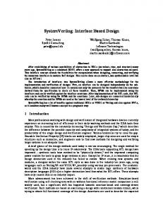
When handling bus protocols of just minor complexity, the interface client requires a finite state machine to handle the protocol. The client then knows in what states data must be sent and received, and how to operate the control signals on the bus. Our prime goal is to implement a slave with little or no knowledge about the bus protocol, but still to have the bus control logic inferred within the slave. This would allow for a synthesized IP component to be attached to a bus system with the same protocol as the one dictated by the SystemVerilog interface. The RTL code within the slave should only concentrate on sending and/or receiving data and implementing the custom function of the slave. In order to obtain this, we want to retrieve protocol specific information from the SystemVerilog interface, packaged as functions and tasks. The figure below shows how methods declared in the interface are instantiated together to form an FSM. One method infers the state holding elements, while the other method infers the logic driving the FSM outputs. Other methods declared in the interface are invoked to access the bus, e.g. get or send data. These are all without state holding elements. Objects: data, ctrl
Methods: get, send...
Processes: bus ctrl, etc
Master
Slave
Slave Bus control logic inferred from interf.
FSM
Slave custom logic and state Figure 8. Bus Subsystem Client The SystemVerilog RTL code below implements a simple example of such a bus system, based on the behavioral model shown previously. DesignCompiler produces a successful synthesis result from this RTL code.
SNUG Europe 2004
10
SystemVerilog in Use: First RTL Synthesis Experiences with Focus on Interfaces
interface bus (); param eter int no_slaves = 0; dataword m a_data; addrword ma_addr; bit ma_req; bit [no_slaves-1:0] sl_ack; bit [no_slaves-1:0] sl_req; // bus control processes always_com b begin // Set sl_req[ma_addr] = ma_req // Set m a_ack = sl_ack[ma_addr] end // functions for ma/sl interf. access function bit ma_send (...); ... function dataword sl_receive (...); ... function bit sl_datardy (...); ... // data types and data carriers for FSMs typedef enum int {sl_rdy, sl_busy,...} sl_statetype; typedef enum int {ma_rdy, ma_busy, ...} ma_statetype; ma_statetype ma_state; sl_statetype [no_slaves-1:0] sl_state; // m ethods for FSM inference in ma/sl task automatic sl_fsm_nxt(...); ... sl_state[slave_id]