Systolic Routing in Sparse Optical Torus Risto Honkanen Department of ComputerScience University of Kuopio P.O.Box 1627 FIN-70211 Kuopio, FINLAND
[email protected]
Abstract. In this paper we present an all-optical network architecture and a systolic routing protocol for it. The sparse optical torus network consists of an n × n torus, where processors are deployed diagonally. The systolic routing protocol ensures that no electro-optical conversion is needed in the intermediate routing nodes and all the packets injected into the routing machinery will reach their targets without collisions.
1
Introduction
A distributed memory parallel computer consists of a number processing nodes, local memories of the processors, and an intercommunication network. A possibility to program such kind of parallel computer is to use message passing [1]. Another possibility is to program using shared memory abstraction and simulate the shared memory program on the distributed memory machine. During each simulation step every processing node has a number of packets (memory references) to route. The packets should be routed as efficiently as possible so that the routing delay (latency) is minimized. Our work is motivated by the emulation of shared memory with distributed memory modules [2]. If a parallel computation has enough parallel “slackness”, i.e. large enough number of independant parallel threads in each processor, the implementation of shared memory can be reduced to efficient routing of h-relation [3]. An h-relation is a routing problem where each processor has at most h packets to send and it is the target of at most h packets [4]. An implementation of an h-relation is said to be work-optimal at cost c, if all the packets arrive at their targets in time ch. A precondition of workoptimality is that h is greater than the diameter φ of the network and the network can move Ω(nφ) packets in each step, where n is the number of processors, since otherwise slacness cannot be used to ”hide” diameter influenced latency [2]. Most of the parallel computers on the market use an electronic communication network to transmit packets between processors. A possibility to increase the efficiency of communication is the use of optics. Optical communication offers several advantages in comparison with its electronic counterpart, e.g., a possibility to use broader bandwidth and insensitivity to external interferences. E.g., Saleh and Teich have represented opto-electronic components in detail in their book [5].
Systolic Routing in Sparse Optical Torus
15
In this work we present an all-optical network architecture and a systolic routing protocol for it. The sparse optical torus network consists of an n × n torus, where processors are deployed diagonally. Routing nodes are connected to each other by optical links [2]. The bandwidth of the system is divided in time slots, whose length tp equals to the bypass time of a packet between two consecutive routing nodes. The system operates synchronously. Every routing node has two incoming and two outgoing links, therefore the routing machinery can move 2n2 packets in each time slot. For an n × n sparse optical torus φ = n. In this work we run some experiments to get idea about routing cost in an n × n SOT. We also sketch the theoretical analysis. According to the simulations an n × n SOT offers work-optimal routing of h-relation if h ∈ θ(n log n). In this paper we present a novel packet routing protocol, called systolic routing protocol. Additionally, when a packet is injected into the routing machinery, neither electro-optic conversions are needed during its travel from source to target processor nor any collisions may happen between two distinct packets. In the systolic routing protocol a packet follows the horizontal (or vertical) path as far as it reaches its target column (target row respectively). When a packet has reached its target column (target row respectively), it is turned to its target processor. Section 2 represents structures of routing nodes and sparse optical torus. In Section 3 we introduce the systolic routing protocol. Section 4 represent the analysis of our construction. Section 5 sketches conlusions and future work.
2
Sparse Optical Torus with Systolic Routers
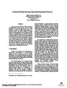
The basic component of routing nodes is the electrically controlled all-optical 2×2 switch. Switches can be implemented by LiNbO3 technology [5]. The switching time of LiNbO3 switches lies in the range of 10–15 ps [5]. The length of packet (lp ) can be Np ×vc , where Np is the size of the packet in bits, vc ' 0.3 evaluated by equation lp = B×r ns is the speed of light in vacuum, r ' 1.5 is the refraction index of fiber [5], and B is the link bandwidth. Assuming the bandwidth to be B=100 Gb/s, the length of a bit in a fiber is lp ' 2 mm. The routing machinery operates under a common clock. A routing node can be in two states. When a routing node routes incoming signal powers of inputs inup and inlef t to outputs outdown and outright respectively, it is called to be in cross state and when it routes incoming signal powers of inputs inup and inlef t to outputs outright and outdown respectively, it is called to be in turn state [6]. The two possible states of routing nodes are represented in Figure 1. A 2-dimensional n × n sparse optical torus, SOT(n), consists of n2 optical routing nodes R(i,j) and n processors (P0 , P1 , . . . , Pn−1 ), where 0 ≤ i, j ≤ n−1. Each routing node has two incoming and two outgoing links. Processors are located diagonally so that processor Pi resides at location R(i,n−i−1) [2]. The two outgoing links of routing node R(i,j) are connected to routing nodes at locations R((i+1) mod n,j) and R(i,(j+1) mod n) . All the connections are assumed to be unidirectional and each routing node is assumed to be capable of receiving and sending one packet per link in a time unit. An example of 6 × 6 sparse optical torus in the turn state is represented in Figure 2.
16
Risto Honkanen
In up
In up Out right
In left
In left
Out down (a) Cross state
Out right
Out down (b) Turn state
Fig. 1. Two possible states of routing nodes
In Figure 2 a disk indicates a routing node, a square indicates a routing node with a processor, and an arrow between two routing nodes indicates a unidirectional link between the nodes. The bandwidth of the system is divided in time slots, whose length tp equals to the bypass time of a packet via a link between two consecutive routing nodes. We call the length of time slot tp the packet cycle. A packet consists of data bits so that the overall length of the time slot measured in time units is tp . Each processing node Pi has n sending buffers (b(i,0) , b(i,1) , . . . , b(i,n−1 )) that have an important role in routing. In order to estimate the feasibility of a SOT(64) let us assume the link bandwidth to be B = 100 Gb/s, and the size of packets to be Np = 128 b. The corresponding lenght of a packet in a fiber is lp ' 26 cm and the length of time slot is tp ' 1.3 ns. Assuming the length of clock cycle of processors to be tcc = 1 ns (corresponding the frequency of 1 GHz), it will take 1.3 clock cycles for a packet to travel between two adjacent routing nodes. The overall amount of fibers is Lf ' 2100m, and the routing time of packets is tr ' 82 clock cycles for each packets. We consider the requested parameters to be reasonable and the architecture to be feasible to construct in the near future.
Systolic Routing in Sparse Optical Torus
17
P5
P4
P3
P2
P1
P0
Fig. 2. A 6 × 6 sparse optical torus in the turn state
3
Routing in Systolic SOT
At the beginning of a routing task, each processor Pi has h packets to route. In the preprocessing phase Pi inserts packets targeted to Pk in its sending buffer b(i,n−(k−i) mod n) . Systolic routing operates cyclically in n phases. At moment t processor Pi removes a packet from sending buffer b(i,t mod n) (if there remains any) and injects it into its horizontal output link. It also receives the vertically incoming packet, which now reaches its target. At moment t each router R(i,j) forwards incoming packets in turn state, if t mod n = 0, and in cross state otherwise. Examples of situations at the beginning of turn phase and cross phase are represented in Figures 2 and 3 respectively. Above, the horizontal-vertical routing of packets was explained. The routing efficiency of the network doubles, if half of the packets are routed analogously first vertically and then horizontally. Note, that these packets do not compete about the links. The idea of systolic routing algorithm is represented in Procedure SystolicRouting.
18
Risto Honkanen
P5
P4
P3
P2
P1
P0
Fig. 3. A 6 × 6 sparse optical torus in the cross state
Procedure SystolicRouting Let t be a global step counter; for i = 0 . . . n − 1 pardo for j = 0 . . . n − 1 pardo if i + j = n − 1 then {Processor nodes} Add packets into buffers b(i,n−(k−i) mod n) endif repeat if t mod n = 0 then Set router in turn state; else Set router in cross state; if i + j = n − 1 then {Processor nodes} Absorb incoming packets from the network; Inject a packet into link outright from buffer b(i,t mod n) Inject a packet into link outdown from buffer b(i,n−(t mod n))
Systolic Routing in Sparse Optical Torus
19
endif endif until All the packets are routed endpar endpar
4
Analysis of Systolic Routing
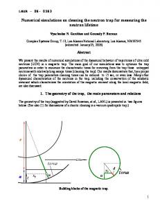
In preprocessing phase, each of the h packets of a processor Pi was inserted in sending buffer b(i,n−(k−i) mod n) , where Pk is the target of the packet. Clearly, all of the packets + 1)n, where Smax is the maximum size of all have been routed after time ( Smax 2 buffers. According to Mitzenmacher et al. [7], supposing that we throw b balls into b bins with each ball choosing a bin independently and uniformly at random, then the maximum load is approximately log b/ log log b with high probability1 . Maximum load means the largest number of balls in any bin. Correspondingly, if we have n packets to send and n sending buffers during a simulation step, then the maximum load of sending buffers is approximately log n/ log log n whp. The overall routing time of those packets is n log n/ log log n + θ(1) that is not work-optimal according to the definition of work-optimality. If the size of h-relation is enlarged to h ≥ n log n, the maximum load is θ(h/n) [8]. Assuming that h = n log n the maximum load is θ(log n) and the corresponding routing time is θ(n log n). A work-optimal routing is achieved. Routing h packets in time θ(h) implies work-optimality. Instead of a cumbersome theoretical analysis, we ran some experiments to get an idea about the cost. In simulations we ran 50 simulation rounds for each occurence using C programming language. Packets were randomly put into output buffers and the average value of the maximum load over all the 50 simulation rounds were evaluated. The average cost were evaluated using equation cave = n+n·Shave /2 , were Save is the average maximum load. Lower bound of the cost approaches 0.5 in the 2-way case, when h/n grows. Figure 4 demonstrates this for n = 16. Figure 5 gives support to the idea that h needs not be extremely high to get a reasonable routing cost.
5
Conclusions and Future Work
We have presented a systolic routing protocol in n × n SOT that offers a collision free packet routing. Additionally, no electro-optical conversion is needed during the transfer and all the packets injected into the routing machinery are guaranteed to reach their destination. We believe that the simple, regular structure of SOT and the systolic routing protocol are useful and realistic and offer work-optimal routing of h-relation if h ∈ θ(n log n). 1
We use whp, with high probability with respect to n to mean the probability at least 1 − O(1/nα ) for some constant α.
20
Risto Honkanen
A possible continuation of the work is to extend the construction to three dimensions. A three dimensional sparse optical torus consists of n3 optical routing nodes and n2 processors that are located diagonally into an n3 torus. The three dimensional construction decreases the size of h-relation that are needed for work-optimal routing.
References 1. Gropp W., Lusk E., Skjellum A.: Using MPI – Portable Parallel Programming with the Message Passing Interface. MIT Press, Cambridge, Massachusetts (1994) 2. Honkanen R., Lepp¨anen V., Penttonen M.: Hot-Potato routing Algorithms for Sparse Optical Torus: Proceedings of the 2001 ICPP Workshops, Valencia, Spain (2001) 302–307 3. Valiant L.G.: General Purpose Parallel Architectures. In Algorithms and Complexity, Handbook of Theoretical Computer Science, volume A (1990) 943–971 4. Adler M., Byers J.W., Karp R.M.: Scheduling Parallel Communication: The h-relation Problem. Proceedings of Mathematical Foundation of Computer Science, (MFCS), Prague, Czech Republic (1995) 1–20. 5. Saleh B.E.A., Teich M.C.: Fundamentals of Photonics. John Wiley & Sons, Inc., New York (1991) 6. Chevalier F., 2002: Introduction Regular Mesh Topologies Using a Novel Self Routing Strategy. Internet WWW-page, URL: http://www.comms.eee.strath.ac.uk/∼franckc (June 24, 2002) 7. Mitzenmacher M., Richa A.W., Sitaraman R., To appear in: Handbook of Randomized Algorithm. Available: http://www.eecs.harvard.edu/∼michaelm/ (June 24, 2002) 8. Raab M, Steger A.: ”Balls into Bins”—A Simple and Tight Analysis. Proceedings of 2nd Workshop on Randomize and Approximation Techniques on Computer Science, (RANDOM’98), Barcelona, Spain (1998) 159–170
Systolic Routing in Sparse Optical Torus
Routing Costs in Systolic Routing 3
n=16
Cost [time slots]
2.5
2
1.5
1
0.5 100
1000 Packets/Processor
10000
Fig. 4. Routing costs when the size of h-relation varies (n = 16)
21
Risto Honkanen
Routing Costs in Systolic Routing 2
(1) (2)
1.8 1.6 Cost [time slots]
22
1.4 1.2 1 0.8 0.6 10
100 Number of Processors
Fig. 5. Routing costs for the size of h-relations (1) h = n log n and (2) h = n2