Abstract- This paper introduces the Tabu Search optimization algorithm to solve the regenerator allocation problem in translucent networks. The problem ...
Tabu Search Optimization in Translucent Network Regenerator Allocation Zhaoyi Pan, BenoIt Chatelain, David V. Plant
Fran90is Gagnon, Christine Tremblay
Eric Bernier
Electrical & Computer Engineering McGill University Montreal, Canada
Departement de genie electrique Ecole de technologie superieure Montreal, Canada
Advanced Research, CTO Office Nortel Ottawa, Canada
Abstract- This paper introduces the Tabu Search optimization algorithm to solve the regenerator allocation problem in translucent networks. The problem consists of finding the minimum number of regenerator nodes which primarily affects the cost of the translucent network. The problem is first solved with an ILP formulation to find the optimal solution without taking into consideration its time performance. The optical reach limit due to the dispersion compensation module and full (static) traffic demand with a 1+1 protection scheme are considered in the network model. The proposed algorithm is then compared with two other heuristics: the maximum infeasibility reduction (MIR) algorithm and the maximum regeneration demand (MRD) algorithm. Numerical results show that the Tabu Search procedure either outperforms or equals the performance of the reference algorithms, while having a lower implementation complexity and comparable convergence speed. Keywords-Tabu search; translucent network; regenerator; optical reach limit;!ull traffic demand; 1+1 protection scheme.
I.
INTRODUCTION
Translucent networks were first introduced by Ramamurthy and al. in 1999 [1]. By taking into account the limited transmission reach of optical signals, translucent network design deals with finding optimal locations for electronic regeneration sites so as to minimize cost. Another design goal is to maximize the protection and facilitate restoration [2]. The optimization algorithm presented in this paper is motivated by the above two constraints to minimize the cost of robust transparent networks. The algorithm calculates the minimum number of 3R (reamplification, reshaping and retiming) regenerators inside translucent networks by using a modem heuristic: tabu search (TS). Finding optical paths by allocating the minimum number of 3R regenerators is a NP-complete k-center problem [2]; therefore, efficient heuristics should be used to solve this optimization problem. Heuristics perform a local search to find a solution which might be a local optimum since unvisited regions in the search domain may contain a better solution. Meta-heuristics are optimization techniques that can find a local optimum solution and escape from it to visit the rest of the search domain. TS is an itemtive meta-heuristics method which is guided by an implemented memory. This memory, which records a number of visited solutions, sets a tabu
(forbidden) list of solutions in order to escape the local optimum and to discover new regions of the search domain. Moreover, TS demonstrates great performance in many research fields including the field of network design [3]. The TS method proposed in this paper has only one short-term recency memory and counters as an objective function that finds the best neighboring solution. Also, the TS algorithm uses few parameters and little memory to deal with large network optimization problems. For example, the two algorithms in [4] select regenerator nodes for each possible lightpath; however, the proposed TS algorithm predetermines a set of regenerator nodes for a network and verifies if it satisfies all of the constraints iteratively. By doing so, a current solution which consists of a set of regenerator nodes can be changed directly in every iteration instead of pre-selecting regenerator nodes over all possible lightpaths in order to make a change in the current solution. Furthermore, the TS algorithm is compared with an integer linear program (ILP) and two previously published algorithms, mentioned above: maximum infeasibility reduction (MIR) algorithm and regeneration demand (MRD) algorithm. The rest of this paper is organized in the following way. In section II, a literature review on translucent networks and the tabu search is performed. In section III the network model is introduced. In section IV, an ILP and the TS optimization function are presented respectively. In section V, the numerical analysis is presented. II.
LITERATURE REVIEW
In dense wavelength division multiplexing (DWDM) translucent networks, photonic transparent cross-connects (OXC) are used at nodes to perform wavelength routing. Retiming, reshaping and re-amplifying (3R) regenerators are also needed to ensure the network performance and the quality of optical signals propagating beyond an optical limit distance [2]. Therefore, a translucent node consists of an OXC fitted with a bank of electronic 3R regenerators. Since 3R regenerators are usually the most expensive resources in a DWDM network, the design objective is to minimize the number of 3R nodes. In translucent network design, both the transparent islands strategy and the sparse placement strategy are studied. In [5]
and [6], it is shown that the sparse placement strategy generally leads to a solution with fewer regenerator nodes than the transparent islands approach. As is stated in [3], TS has been implemented successfully in many combinatorial problems, such as the vehicle routing problem, the traveling salesman problem, the quadratic assignment problem and the multidimensional knapsack problem. More specifically related to network design, the TS method proposed in [7] efficiently solves the problem of routing and wavelength assignment (RWA) in transparent networks. However, that particular TS method applies in transparent networks with scheduled lightpath demands rather than translucent networks with the static full demand which is presented in this paper. Coincidentally, the k-shortest path is computed in the pre-search section of the TS algorithms in both papers. Thus, this paper proposes the TS algorithm to solve, for the first time, the regenerator allocation problem in translucent networks. III.
NETWORK MODEL
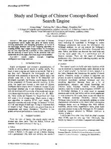
The use of dispersion compensation modules is considered in this study [8]. More specifically, physical impairments, such as chromatic dispersion, polarization mode dispersion, amplified spontaneous emission (ASE), and propagation losses are converted to one single constraint: optimal reach limit. The network model in this paper uses a full traffic demand with a 1+ 1 link-disjoint protection scheme for all connections, similar to [9]. The general idea is to satisfy a worst-case scenario network model in order to have a robust network design. Since all possible connections are taken into account, the obtained solution is valid for busiest traffic scenarios with no network defect. Fig. 1 gives a detailed view of the node model used in this paper. A node can either be transparent (without 3R regenerator) or translucent (with 3R regenerator), but every node has an OXC switcher. The type of amplifiers and DEMUXs vary with the number of wavelengths that are coming in and out of the node. In this modeling, the cost of a network depends primarily on the number of translucent nodes,
axe
Figure 1. Node Model: the optional dashed box determines whether a node is an 3R regenerator node or not.
since adding 3R regenerators is more expensive than adding wavelengths. Consequently, the proposed TS method only attempts to finds the routes of each connection and the minimal number of 3R regenerator nodes; the wavelength assignment is assumed to be performed separately. IV.
OPIMIZATION FUNCTIONS
The output of the ILP and TS optimization functions is the minimum number of 3R regenerator nodes, and the primary and protection paths assignment. The ILP can be used to find optimal solutions for small networks and can also be used to approximate performance bounds for the TS procedure.
A.
ILP formulation
To describe the ILP model, a notation similar to that of [10] is used: G = (V, E): A directed graph with the set of network nodes V and the set of optical links E. i,j: Originating and terminating nodes of a lightpath.
Values given: R:
The optical reach distance. A large number, K> R The number of nodes in the network. The number of connections. Since a full demand matrix is considered, there are N 2-N connections. P: The network physical topology matrix. If Pij = 1, there exists a physical link between i and j. P is of size N by N. D: The distances matrix. The distance in kilometers between nodes i and j is given by Dij. D is of size N by N. S: The set of source nodes. is the source node of the qth connection (q = 1, 2, ... , Q). T: The set of destination nodes. Tq is the destination node of the qth connection. Lt: The set of "outgoing" links of node i, that consists of the set of unidirectional links having the node i as one extreme and leaving the node. L; : The set of "incoming" links of node i, that consists of the set of unidirectional links having the node i as one extreme and pointing towards the node.
K: N: Q:
sq
Variables:
a& : A binary variable indicating when it equals to
1, that for the qth connection, the link between nodes i and j is on the primary path. Similarly, ifJ equals to 1 if the link between nodes i and j is on the protection path. bJ : A binary variable indicating when it equals to 1, that for the primary path of the qth connection, a regeneration channel at nodes i is used for the signal propagation toward node j. Similarly, b;jq indicates when it equals to 1 that for the protection path, a regeneration channel at node i is used for the signal propagation toward node j. c~: The accumulated distance at node i in the direction of node j, for the primary path of connection q.
X:
CJ corresponds to the accumulated distance at node i in the direction of node j for the protection path. A binary vector of N elements representing the presence (1) or the absence (0) of regenerators at each node.
•
c~ ~ LDi/aZ +K(alk -1), elk ~ LDi/aii +K(alk -1) ~~
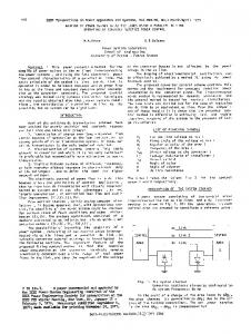
In the example given by Fig. 2, the optical path of connection # 1 is represented. The source node is node 1 and the destination node is 6. The optical path is [1 2 3 6], makinga: 2 ,a;3 and
a;6 equal to
At intermediate nodes, if there is a regeneration channel at node i, the accumulated distance from node i to j corresponds to the link distance D;i
c~ s LDi/aZ + K(I- bi/ ~ clk s LDi/aii + K(I- b;l) ~~
1. Since link 1-2 is of length
10, the accumulated distance C;3 is equal to 10. With b~6 = 1, node 3 is a regenerator node. Since there is a regeneration channel at node 3, X(3) = 1.
~~
(9)
~~
\lq, \II ~ sq u
r q, \lk E L7 ,
where K is a constant that exceeds the value of R. •
At intermediate at node i, the corresponds to distances and to
nodes, if there is no regeneration channel accumulated distance from node i to j the sum of the previous accumulated the link distance D;i
c~ ~ LCi/ + Di/aZ -Kbi/ +K(a lk -1) ieLI
elk ~ LCi! + Di/aii -Kbi/ +K(alk -1) Figure 2. 6 nodes optical network.
The design guidelines for the routing and regenerator nodes allocation of translucent network with 1+1 protection can be summarized as follow: •
Minimize the number of regenerator nodes:
LX
\lq, \II ~ sq u
n •
At intermediate nodes, the accumulated distance at node i in direction of node j must be inferior to the optical reach distance R if the outgoing link i j is selected. Otherwise, the accumulated distance equals to 0:
•
No regeneration needed at the source node:
(1)
n=l
•
A single link coming out of the source node is selected:
c;jsRaij' C";JsRaij
L a;j=I, LaJ=1 \lq,i=Sq.(2) jeLt jeLt •
A single link coming in the destination node is selected:
La;j ieL) •
= 1,
L aJ = 1
ieL)
\Iq, j = Tq .
a;j =0, aJ =0 \lq,i=Tq,\ljEL;. •
rtq,'~ir£SuD. (5)
s 1 \lq, Vi ~ sq u Tq, \lj E L; .
(6)
Accumulated distance from the source nodes does not depend on previous accumulated distances:
c;j = 0, C";J = 0 Vq, i = sq , Vj E L; . •
•
(7)
All incoming accumulated distance to the source nodes are equal to zero:
CJi = 0,
eJ; = 0
Vq, i = sq , Vj E L~ .
(8)
(11) (12)
No regeneration at the destination node:
b;j = 0, b;X = 0 \Iq, j = T q, \liE Lj .
(13)
A regeneration channel can only be activated if the link is chosen:
b;j
s a;j, b;X s aJ
\lq, i = 1,2,... ,N, \lj E L; .
(14)
•
If a regeneration channel bij i is used, then node i is an 3R node:
•
The primary and protection paths must be linked-disjoint: a~ + aJ s 1 i = 1,2,... ,N, rtj E L; (16) i = 1,2,... ,N, \lj E L;
Xi -b:J ~ 0, Xi
At intermediate nodes, an incoming link (i, j) and outgoing link (j, i) can not be selected simultaneously:
a;j + aji S 1, aJ + aJ; •
(4)
At intermediate nodes, if one incoming link is selected, an outgoing link must also be selected:
La~=LaJi' LiiJ=LaJ jeLt jeE; jeL;+ jeE; •
•
Vq,Vi~SquTq,VjEL;.
q -0 b- q -0 \-/ '-sq \-/' L+ bij-' ij vq,l- ,vJE i '
(3)
Outgoing links from the destination node must not be selected:
r q, Vk E L7 .
•
N
Minimize
(10)
ieLI
-"b;l ~ 0
Vq, i = 1,2,... ,N, Vj E L;. (15)
TS procedure
B, 1)
Algorithm Complexity Analysis
Basically, the algorithm goes through each node-to-node connection from the network traffic demand, and finds the kshortest paths for both the primary path and link-disjoint protection path. Then the iterative TS algorithm starts with an initial solution which consists of an arbitrary binary vector
array that records transparent nodes as 0 and translucent nodes as 1. Also, there are two types of lightpaths: translucent (with 3R node) or transparent (full optical path). At each iteration, the current solution is passed to a verification function that checks if the current solution can satisfy a 1+1 protection lightpath pair out of all the possible pre-calculated k-shortest paths. If the current result is correct, then one 3R node is dropped from the current 3R nodes. If the current solution is incorrect, then one OEO node is added from the current transparent nodes. Each node that has been added or dropped is updated in the tabu list as tabu (unable to add or drop) for a few iterations, the number of which is preset by function parameters. Once again, this is a NP-complete k-center problem [4] with N as the number of nodes in a network. The time complexity of the following three algorithms is compared: the MIR and the MRD from [5], and the TS algorithm in this paper. Only the search part but not the initialization part of the algorithms is considered for comparison purpose.
computation. While the TS algorithm achieves the same results in term of number of 3R nodes, it does so in less than 2 seconds.
Figure 3.
For larger network such as the one represented in Fig. 4, the ILP model cannot be used. The TS algorithm is thus compared with two other heuristics: the MIR and MRD algorithms. (~)--841
The MIR has a time complexity of O(N 3), and the MRD has a time complexity of O(N 2). In the TS algorithm, the time complexity is mainly based on the verification function which checks through every node-to-node connection giving a time complexity of O(N 2). A translucent path requires O(N) time complexity to check, and a transparent path requires 0(1) to check. If the verification function checks through the k-shortest paths of each node-to-node connection, then the worst-case overall time complexity of the TS algorithm would be O(N 3). As shown in table 1, the TS algorithm time complexity sits between the MIR's and the MRD's. 2)
10 nodes (a) and 11 nodes (b) optical networks. \
,-. (175 .
(2)
1\
\T~832---{10)" T ,"-' 7
605
'. 1
I
431'(\14h. 31 9
r
~
(26) (23,434 -
,18)
119~'
~o
1196(24t-482-