knowledge about user tasks and end user characteristics to the utmost extent. They not only support end users throughout the work flows they are involved in ...
IEEE TRANSACTIONS ON SYSTEMS, MAN, AND CYBERNETICS—PART A: SYSTEMS AND HUMANS, VOL. 30, NO. 5, SEPTEMBER 2000
509
TADEUS: Seamless Development of Task-Based and User-Oriented Interfaces Chris Stary, Member, IEEE
Abstract—Task-based and user-oriented user interfaces utilize knowledge about user tasks and end user characteristics to the utmost extent. They not only support end users throughout the work flows they are involved in their business, but need also to be constructed throughout a development process that allows to proceed without loss of application context and user feedback from requirements specification to code generation. The concepts behind the task analysis/design/end users systems (TADEUS) approach to enable seamless development based on end user tasks are a semantically rich representation scheme, a model-driven development procedure, a diagrammatic notation and unifying specification scheme. They are to be used for task analysis, design, and code generation. This way, interactive applications can be developed seamlessly, starting with task analysis, proceeding with design, and generating customized user interfaces for the actual task performers (users). Specifications comprise problem domain knowledge, work processes, user roles and personal profiles, as well as interaction modalities (required for task accomplishment). For user-interface prototyping the TADEUS environment contains a model interpreter that executes structure and behavior specifications. This way, early feedback on task-based portals can be provided by users. In this paper we detail the latest developments in the TADEUS project when implementing a work-process based usability life cycle. We review the underlying methodology and the features of the TADEUS environment, in order to demonstrate the benefits for developers and users resulting of smooth transition support for and between the different stages of development. Index Terms—Customization, intelligent user interface management, interactive work design, knowledge representation, life cycle management, model-based development, object-oriented modeling, object systems, portal generation, prototyping, task analysis, usability engineering, user-centered design, workflow modeling.
I. INTRODUCTION
I
T IS now commonly accepted that developing interactive software requires consideration of the interaction between humans and computers from a work and users’ perspective rather than focussing primarily on technical issues. In doing so, development activities concerning the user interface are no longer add-ons to the required software-engineering activities. The knowledge for human-centered user interface design stems from the organization of work and the cognitive and social context of technology use (see, e.g., [29]). In case the user interface interferes with intended user activities for task accomplishment, it might become a source of trouble, since users might get worried and the results of work might lack required quality, (see, e.g., [6], [28], [30]). Manuscript received December 17, 1998; revised June 1, 2000. This paper was recommended by Associate Editor C. C. White. The author is with the Department of Business Information Systems, Communications Engineering, University of Linz, 4040 Linz, Austria. Publisher Item Identifier S 1083-4427(00)07049-1.
Although a number of task-based and user-centered development approaches have been reported, a thorough integration of structured development techniques and user interface development procedures is still lacking. Few authors (e.g., [6], [8], [47], [48]) have addressed this deficiency admitting “there is usually a certain amount of craft and creativity involved in producing effective designs” [48, p. 2] and “designing the fundamentals of object-oriented Graphical User Interfaces to meet user needs has been done seemingly by magic” [48, p. 16]. Most researchers tend to apply techniques either from software or knowledge engineering for user interface engineering when striving for structured or knowledge-intensive development techniques [3], [10], [47]. However, neither the Waterfall [40] nor the Spiral model [5] for software development has been designed for interactive systems engineering. Thus, both do not actively support the development of interactive systems based on task or user representations. As a consequence, conceptual frameworks for usability engineering and life cycles related to task and user representations have been proposed, e.g., [1, p. 120], [25, p. 104]. They do not only focus on acquiring (usability engineering) knowledge and mapping this knowledge to development activities. They also try to bridge the gap between structured development and user interface development in a rather evolutionary way. Studying the work addressing that gap [12], [13], [34], [35], reveals the following topics to be crucial for bridging the gap: • acquire and represent knowledge about users and tasks, in order to achieve a high degree of adaptability; • define accurate representation schemes as well as flexible notations; • build tools capturing more than a single phase of development; • provide early feedback to end users; • shift from engineering to participation of task performers throughout the development; • educate designers to develop thorough domain knowledge and context sensitivity. Consequently, the key features for task-based and user-centered support mechanisms are continuous support of development phases, starting out with analyzing the work situation of users and their profiles, and a “language” both developers and users understand. The latter is required to communicate elicited knowledge, design ideas, and envisioned computer support. Providing these features ensures seamless development. It means to be able to successively transform user and task inputs into a technical artifact in a way that 1) all relevant tasks and user properties can be captured (taking into account organizational and cognitive constraints) and 2) it can be traced by actual users (task performers) and (system) developers how the artifact has
1083–4427/00$10.00 © 2000 IEEE
510
IEEE TRANSACTIONS ON SYSTEMS, MAN, AND CYBERNETICS—PART A: SYSTEMS AND HUMANS, VOL. 30, NO. 5, SEPTEMBER 2000
been created through stepwise refinement and transformation of task knowledge. Seamless development can only be achieved when the development process is understood as a collective activity rather than a sequence of isolated tasks or phases, as already recognized by Ehn [13, p. 109]. This commitment ensures the above-mentioned shift from engineering activities to an active participation of users. However, it requires support of views on the development knowledge, as observed by Kotonya [23] and Schewe et al. [36]. It also requires an (activity-theoretical) understanding of representation as “mediating the relation between designers and their products” (according to Bodker [4, p. 110]). One of the major requirements to representations is that they have to “hold on to aspects of the computer application to be, and, at the same time, facilitate the design process” [4, p. 111]. Hence, representations have to support the process of development and the product as a result of this process [26, p. 20]. Object-oriented modeling schemes seem to become commonly used for development representations (e.g., [7], [17]), although major deficiencies have also been found [22], [39]. For presentation, another observation seems to be relevant: When software development tends to be knowledge-intense (as being the case for human-centered design), diagrammatic languages, such as UML, and visualized contents facilitate the development process (e.g., [16], [32], [45]). However, the best representation scheme will fail unless its contents can be communicated successfully to task performers, either in terms of meaningful abstract terms or concrete interaction elements. Both issues have been addressed in the TADEUS-project. Task analysis/design/end user systems (TADEUS) [41] is an approach that intends to enable seamless development support. It addresses domain experts, users, analysts, designers, usability engineers, and programmers. It focuses on representation in the tradition of “containers of ideas” [4, p. 120], facilitates the process of design, the specification and generation of results, and finally, makes the process of development easily accessible and traceable for the listed user groups through diagrammatic (re)presentation. TADEUS (re)defines usability engineering through an integrated a) model-driven; b) task-based; c) user-oriented; and d) object-driven life cycle. a) Model-driven development allows for multidimensional and viewpoint-related specification and generation of interactive software. Several aspects, namely, the content of work, the organization of work, the technology used for task accomplishment, user skills and capabilities can be handled in a structured way throughout the phases of development. However, as we will see, integrating those aspects requires a redefinition of traditional techniques for model-based user interface development, in order to capture the nature of the design process: The design process is considered as a continuous switch between perspectives, namely, between user tasks, user roles and profiles, problem domain data, interaction styles for task accomplishment, and the already integrated parts of the specification of an application. Revisited model-driven development supports a nonlinear sequence of view-driven activities.
b) Task-based development takes into account the organizational and business context of interactive software systems. Tasks are those entities that have to be supported from the structural point of view as well from the dynamic perspective, i.e., the accomplishment of problem-solving activities. Hence, similarly to the introduction of workflow management systems, the organization of a business, the functional roles, as well as the assignment of users to roles (in our case also to modalities of interaction) have to be specified in the course of (interface) development. c) User-oriented development reflects on the situation of task performers distributed throughout business processes, probably involved in more than one process, and hence, requiring an individual organization of tasks. In addition, individual skills and preferences are crucial for role and task assignment. Besides comprehensive representation of this knowledge (e.g., through user modeling) user participation is substantial in the course of development. Both, the diagrammatic (re)presentation of design knowledge and prototyping tuned to that representation (see below) allow the utmost individual involvement of users throughout the development procedure and its phases. d) Object-oriented development enables the diagrammatic and unifying treatment of analysis and design knowledge, and supports its implementation. Such a strategy is a conditio-sine-qua-non to ensure smooth transitions from analysis to design and from specification to code generation (without loss of contextual information). Furthermore, it allows the iteration of analysis and design activities, despite of already implemented software components. Finally, it facilitates the communication among developers and users. The diagrammatic (re)presentation has not only been chosen for the sake of communicating development ideas, user participation, and traceability of the design process, but also to enable workflow-oriented prototyping: “Early prototyping is fundamental to the success of operations supporting software products” [2, p. 2], in particular, due to the following reasons. 1) The prototype provides a vehicle for systems engineers to better understand the environment and the requirements problem being addressed. 2) A prototype is a demonstration of what is actually feasible with existing technology, and where the technical weak spots still exist. 3) A prototype is an efficient mechanism for the transfer of design intent from system engineer to the developer. 4) A prototype lets the developer meet earlier schedules for the production version. 5) A prototype allows for early customer interaction. 6) A prototype demonstrate to the customers what is functionally feasible and stretches their imagination, leading to more creative inputs and a more forward-looking system. 7) The prototype provides an analysis test bed and a vehicle to validate and evolve system requirements [2]. In addition, prototyping allows evolutionary development, as recognized by Schneider [37, p. 523], meeting the demand for
STARY: TADEUS: DEVELOPMENT OF TASK-BASED AND USER-ORIENTED INTERFACES
handling the design process as a highly dynamic set of activities, since the “specification and the design of the algorithm or the system architecture often constitute an ill-defined problem type” [32, p. 89f]. Methodologically, TADEUS bridges the gap between structured software development and traditional user interface development through supporting 1) the acquisition and representation of tasks and organizational information; 2) the mapping of acquired information to interaction features; and 3) the generation of prototypes based on the results of 2) to ensure early feedback and involvement of end users. As such, TADEUS does not only show “what will take place” and “how this is to take place” [4, p. 120], but why this is to take place. It implements both, the quest for capturing nonfunctional requirements and constraints, but also the quest for understandable traceability [45]. Hence, (re)presentations and prototypes are not only containers for design ideas, but also serve as basis for collaborative reflection on artifacts and for active involvement of task performers. In the following, we discuss the latest TADEUS developments with respect to a usability engineering life cycle that supports design as a (nonlinear) process as well as the specification and evaluation of its results, in particular task-complete user interface prototypes. We start out with discussing related work in Section II, and review TADEUS in Section III including task-oriented prototyping. Section IV concludes the paper summarizing the objectives and results of our work, and sketching areas of our further research. II. RELATED WORK In this section, we primarily focus on the procedures, representation schemes, and tools being developed for task- and user-centered interactive software development support. Currently, most of the existing approaches stem from the field of human-computer interaction. Recent developments in the field of organizational development, e.g., business process (re)engineering, however, might influence research in the future. There, issues such as enriching business models with objects to facilitate the software development process (e.g., [15], [49]) following the tradition of [19], and how to focus on people needs in the course of organizing tasks and knowledge (e.g., [38]), have been started to be discussed from a methodological perspective. Future results might have significant impact on the methodological integration of organizational and interactive software development, as well as the tool corresponding to integrated development. In particular, since currently the relationship between user interface technology and organizational development is not very well defined, as the latest developments in the field of enterprise-resource planning systems show: Most of the software producers in that area, e.g., SAP, FabaComponents, tend to link the generation of user interfaces or portals to process specifications, however, at a very elementary level and in a straightforward way (cf., e.g., [35]). A. Schemes for Representation and Procedures for Development Experiencing the need for linking task and software development [33], [34], several projects have been started to tackle
511
Fig. 1. ADEPT approach.
this issue from the methodology and tool perspective. For instance, in the ADEPT project [21], [47], several models have been identified, namely, for task definitions, the specification of user properties and the user interface. These models are also part of the ADEPT environment—see also Fig. 1. The task model does not only comprise a representation of existing tasks, but also envisioned ones. The latter representation also serves as container for design ideas. The (abstract) interface model contains both, guidelines for feature design, and the features required to implement the envisioned tasks through a GUI. As we will see, the ADEPT task model is similar to the TADEUS task model. However, it also captures part of the TADEUS problem domain model. In TADEUS there is no difference between envisioned and existing task representations, since multiple designs might be created in the course of development. In TADEUS both, existing task models and visions about the future of task accomplishment can be handled through versioning of (application) models. Moreover, in contrast to TADEUS, the ADEPT user model does not contain access and manipulation permits for elements of the data according to the relationships between tasks and user roles. Finally, the ADEPT abstract interface model corresponds to the TADEUS application model (and the prototyping engine), since it comprises the behavior of the application at an implementation-independent layer (including the interaction control). In ADEPT, a top-down design and prototyping approach has been implemented for development: After task analysis (leading to a task model capturing existing tasks), a description of the process the users would like follow when interactively supported has to be elicited (leading to an envisioned task model). The procedure concludes with a detailed specification of the user interface for the envisioned tasks, termed the abstract interface model. In principle, this procedure can also be followed when using TADEUS. In that respect, ADEPT and TADEUS differ from the other development approaches, such as [9], since the others support merely functional design representations rather than task and user modeling. HUMANOID [24] can also be considered as a model-based approach. Its development procedure starts with a declarative model of how the interface should look like and behave (in the sense of the above mentioned envisioned task model), and
512
IEEE TRANSACTIONS ON SYSTEMS, MAN, AND CYBERNETICS—PART A: SYSTEMS AND HUMANS, VOL. 30, NO. 5, SEPTEMBER 2000
should be refined to a single application model that can be executed. Each user interface is handled according to five semi-independent perspectives, namely, 1) the application semantics which is captured through domain objects and operations (similar to the TADEUS problem-domain data model); 2) the presentation part emphasizing the visual appearance of the interface elements; 3) the behavior part capturing the input operations, e.g., mouse clicks, that can be applied to presented objects, and their effects on the state of the application and the interface; 4) constraints for executing operations that are specified through dialog sequencing; 5) triggers that can be defined through specifying operational side-effects. The life cycle in HUMANOID corresponds to iterations of design—evaluation—redesign activities based on interpretations of the executable model of the interface. As such, it corresponds to the TADEUS approach. However, HUMANOID lacks comprehensive user modeling as well as a structured procedure how to derive problem domain data and interaction modalities from declarative task specifications. Both are required to ensure consistency of design knowledge and to enable to check for the completeness of specifications against the tasks and the organization of work at hand. Similar to HUMANOID several approaches have been designed: For instance, deBaar [9] suggested to start with the creation of an application data model (using the editor D2M2edit), then to instantiate interaction objects corresponding to the data, and to define control selection as well as layout rules for interaction (using the tool Devguide). Based on these specifications an application’s interface can be generated. Again, there is no way for dealing conceptually with tasks, user properties, and dynamic aspects (e.g., workflows) produced during run time of the interface. In UIDE and GENIUS some improvements have been introduced with respect to handling the dynamics of user interfaces. GENIUS [20] uses entity-relationship diagrams, and as such also data modeling, as the starting point for the specification of user interfaces. Furthermore, GENIUS provides a Petri-net approach for modeling behavior, in addition to a knowledge base for layout specification. However, there is no evidence for task-based and user-oriented support for the generation of user interfaces. The UIDE approach [44] requires the design of application objects and dialog elements, before application model classes can be mapped to functional user interface components. The latter are executable to generate user interface elements. We can conclude that, with respect to schemes for representation and procedures for development, most of the existing approaches are based on concepts to 1) capture the semantics of applications through problem domain (data) objects and associated constraint mechanisms, at least at the structural level; 2) construct some kind of an application model that can be processed to generate user interface prototypes.
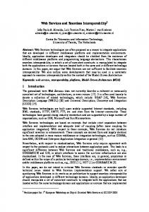
Fig. 2.
Runtime architecture of UIDE.
However, in most of the cases, the (semantic) relationships between tasks, problem domain data, and interaction modalities remain implicit, in particular at the level of behavior specification. In addition, the issue of user modeling or role specification has been addressed rarely. There seems to be consensus with respect to notation and language of representation: Most of the existing techniques use object-oriented languages and/or notations, at least when it comes to implementation (see also tool discussion below). For the representation of tasks notations different from object-oriented specifications, such as goal trees, are used. In these cases, neither the transformations to class/object models nor behavior specifications of GUI-elements have been made explicit. Moreover, it is assumed that specifications are consistent and complete, without checking for these characteristics. Hence, from the methodological perspective, neither structured procedures, consistency checking of application semantics and task completeness, nor the traceability of the development process have been supported sufficiently and/or in a comprehensive way. B. Tools for Prototyping and Software Generation Tools for supporting task-based prototyoing and interactive-software generation have to provide a high level of expressivity (according to Myers [27]). Consequently, common interface builders providing instantiations of prefabricated dialog elements do not suffice. In addition, development knowledge and specifications have to be communicated properly through these tools. Hence, task-based development support tools do not only require complex constructs to capture workflow-driven structures and behavior specifications (including the refinement to modality-specific operations at the user interface), but also editors to manipulate (diagrammatic) specifications. Devguide [9] creates a user interface directly from the data model. An inference engine applies control selection and layout rules to the application data objects. It also adds an relevant configuration data of platform-specific controls to dialog elements. In UIDE [44] the runtime architecture executes a dialog sequence that is based on the specification of application semantics. When the specification is changed, the sequence is also changed (see Fig. 2). Usually, specifications are not communicated to task performers. Furthermore, the completeness and consistency are not checked for with respect to the task level. The application model keeps track of design information at a high level of abstraction, and finally controls the interaction at run time. The model consists of three layers, capturing the functionality of the user interface at three levels of abstraction. At the top layer, the model should capture the semantics of operations at the user interface. At the medium layer, operations
STARY: TADEUS: DEVELOPMENT OF TASK-BASED AND USER-ORIENTED INTERFACES
Fig. 3.
513
TADEUS frame of reference.
should be specified according to an existing interface paradigm, such as GUIs, but independent of any specific application. At the bottom layer, concrete operations, such as mouse clicks, are defined. Although the definition of layers indicates steps of structured interface development through refinement activities, it is not clear, how the layers have to be related mutually, in order to ensure the intended application behavior. The ADEPT interface generator [21], [47] is driven by built-in heuristics, by the input of the user modeling component, and explicit designer inputs through declarative specifications. It generates the layout of the user interface, and allows task-conform handling of interaction elements. Recent developments, such as MOBILE [31], also support layout generation, and execute refinements of task models in a direct manipulative, thus, easy to handle way. However, in the course of development the usability cycle task modeling—design—prototyping has to be iterated completely, since there does not exist an implementation-independent behavior specification that is semantically linked to the task representations. Concluding, several deficiencies of existing tools for prototyping and code generation have become evident: 1) Integration and Contextual Processing. In case application semantics is specified in traditional data models, it cannot be guaranteed that the resulting user interface is task-based and/or user-oriented. In particular, tasks and user properties should be represented and linked to interaction modalities explicitly, in order to allow tracing the refinement of tasks to functional (interaction) properties. The latter requirement addresses tool support for the design process itself (rather than the product and its specification). Hence, facilitating the time-consuming task of interface generation does not necessarily support the nonlinearity of the design process itself. 2) Consistency and Completeness. As an implication of 1), the completeness and consistency of development knowledge with respect to task accomplishment and user profiles cannot be guaranteed. Once explicit representations of task and user properties exist, algorithms can check for the consistency and the completeness of the subsequent refinements. 3) Traceability and Understandability. The traceability of the development process as well as incremental devel-
opment activities require unifying and diagrammatic notations that capture the structure and the behavior of an application as well as the underlying models (e.g., the data model). As a consequence, either particular models or views on the application model have to be kept throughout development, although an integrated application model is required for prototyping or code generation. Each of the models have to provide specifications that can be communicated among users and developers. In summary, neither current tools nor concepts meet the identified set of needs for seamless and comprehensive development. Major deficiencies concern the incompleteness of knowledge sources, the inadequacy of representation schemes, and the lack of explicit steps of integration, at the conceptual, the methodological and the tool layer. As a consequence, development overhead might occur due to inconsistent specifications, incomplete solutions or problems in communication. In TADEUS existing concepts, such as the provision of different layers or the use of a diagrammatic notation, have been integrated and enhanced to enable task-complete and user-oriented development of user interfaces seamlessly. III. TADEUS TADEUS [41] targets a comprehensive development methodology, unifying and diagrammatic (re)presentation of development knowledge, and the execution of this knowledge to generate user interfaces or portals. In the following we introduce the conceptual framework of TADEUS, the methodology including the scheme of representation, and the tool corresponding to the framework and the methodology. As shown in Fig. 3, the TADEUS framework enables to transform and refine business intelligence into user interfaces or task-specific portals. The business intelligence might be modeled through business process specifications or acquired through work or business analysis. It is elaborated to task and user specifications that are related to problem domain data and interaction modalities. Structural and behavioral specification of these knowledge items enable the construction of an application model after certain steps of refinement. The resulting model serves as input to a modality-specific and workflow-driven engine generating user interfaces.
514
IEEE TRANSACTIONS ON SYSTEMS, MAN, AND CYBERNETICS—PART A: SYSTEMS AND HUMANS, VOL. 30, NO. 5, SEPTEMBER 2000
According to its claim for supporting analysis, design, and implementation TADEUS has to provide a technique for work analysis. It is called TADEUS task analysis representation technique and enables the elicitation and acquisition of business intelligence. The results serve as input to subsequent design activities, starting with task modeling and leading to prototyping based on an application model. A. Analysis DEUS ask nalysis and epresentation technique The (TATAR) [42] considers analysis not only to be an analysis of work organizations and business processes, but also an analysis of social settings, contents, proposals for reorganizing work, skill requirements and individual profiles. TATAR targets toward identifying and describing units of work and resources required for successful work performance (in the context of the application domain and social settings at hand). Resources in this context concern both, individual ones, such as skills, knowledge, physical and cognitive capabilities, experience, and the work environment (e.g., control structures, activities, and tools). The analysis may either be performed by system analysts, organization developers or usability engineers that are well trained and experienced in performing analysis of work and tasks. The analysis should not focus particularly on technology but on the situation at work as employees and management perceive it. Technology comes into play, as soon as there exists some kind of technological support for the accomplishment of tasks. The analysis tries to capture both the organization’s (i.e., management) and the users’ point of view. Both perspectives have to be acquired, and might have to be migrated. At least they are integrated in the representation of results, even if they conflict. They latter case is very common, namely, as soon as different ways for solving a particular problem are elicited and have to be represented as part of the organizational intelligence. The entities to describe a business from the management perspective are in TATAR: • business processes, including organizational units, functional roles required for task accomplishment, tasks and subtasks, and events and conditions relevant for task accomplishment; • all material comprising immaterial data and physical objects of manipulation; • tools (including computer support through hardware and software). When capturing individual work spaces detailed knowledge should be elicited about 1) the type of tasks; 2) individual problem solving procedures and organization of task accomplishment; 3) individual proposals to reorganize both the global and individual work space; and 4) the job satisfaction. Hence, the major steps to be followed in TATAR (methodology) are the following. 1) Capture business processes as management envisions them currently. 2) Elicit how they are lived, approaching for each work space or process at least five task performers (responsibles and operational staff). 3) Integrate, at least combine the acquired knowledge in a specification document.
4) Iterate 1)-3), as long as it is possible to gain deeper insight into the context and the requirements of the software to be developed. Depending on the type of business and the “structuredness” of the organization at best two complimentary of the following methods are used for the elicitation and acquisition of knowledge: document analysis, observation, introspection and retrospective protocols, (structured) interviews, think-aloud protocols, and ethnographic studies. These methods deliver insights in the most effective way, since in TATAR not only the results of the analysis, but also the process of analysis should be made transparent through a proper documentation (see also [11]). The process and results might be documented through a media mix (recordings, notes, etc.), depending on the tasks/organization under investigation and the possibilities for acquisition and elicitation. B. Representation Since the transformation from analysis to design should be as seamless as possible (minimal reduction of semantics, minimal loss of context for further developments), structural and behavioral specifications have to be integrated into a single model of TADEUS, namely, the business intelligence model. In order to achieve that integration, a semantically rich language and a diagrammatic notation have been developed—the language definition and a user guide including examples can be downloaded from http://www.ce.uni-linz.ac.at/research/TADEUS. Since the features have been tuned to the TADEUS models used for design and prototyping, the business intelligence model can directly be imported into these models. The features capture the most important elements for business process modeling. • The organization and/or organizational units that represent the set of departments the organization is composed of, or vertical and/or horizontal structures, such as hierarchical layers within an organization. • Roles, together with the activities and the materials (see Activities and Materials), that are processed in the course of task accomplishment. They represent the part of the organizational intelligence that is required to run business processes. They address skills and required qualifications of people from the technical, organizational, cognitive, and social perspective. • Activities that are actions or operations that might be performed by task performers (as instances of roles) or machines, respectively, in order to accomplish tasks. Task accomplishment might be based on temporal and causal constraints between activities. • Materials that may either be data or raw materials being processed to accomplish tasks. They are assigned to activities and, finally represent the results of work/business processes. • Tools that comprise those parts of work organizations, too, that might not be considered to be part of the user interface (like the mouse or software functions are), but are required to accomplish tasks or to facilitate task accomplishment, such as production machines. • Events that are those points of reference that trigger activities, and might be specific for the business processes to be supported. Events might have to be described at sev-
STARY: TADEUS: DEVELOPMENT OF TASK-BASED AND USER-ORIENTED INTERFACES
515
Fig. 4. Sample part of a business intelligence model (ORD).
eral levels of detail, in order to understand activities when particular situations occur. • Relationships: Besides the common object-oriented relationships has-subclass, has and has-part, a variety of links is provided to network organizational units, roles, tools, materials and activities: “Employs” relates organizational units to roles. “Handles” denotes the responsibility of a role for a particular activity: The individual behind the role may either delegate this activity to another agent and/or monitor its accomplishment, or perform it by him/herself. “Creates” denotes the creation of material through an activity. “Concerns” involves roles via “handles” or “controls,” activities, materials, tools, or other relevant factors for task accomplishment (e.g., quality measures). Typical assignments for this relationship are mediate factors, such as qualifications to operate a tool or to create materials. In case no activity can be assigned to a role, “informs” is used to mutually relate functional roles. It denotes the passing of information (about material or an activity) from one role to another. “Controls” denotes the control of activities or material (that might concern an activity) through a role. “Requires” denotes material that has to be processed, in order to perform an activity. “Before” is set between two activities, denoting a sequence of activities according to the direction of the link. “Is-Based-On-Mat” is a relationship between two materials. It denotes the interdependence of materials from the material perspective. This way, a causal (rather than an aggregation) relationship is established, since a particular material cannot exist without the other (on the long run). “Corresponds-To” involves activities and the “before” and “is-based-on-mat” relationship. It denotes a correspondence between two activities, with these activities evoking each other mutually. However, the conditions of occurrence have to be detailed in the design speci-
fications, i.e., TADEUS object behavior diagrams (see below). Other complex relationships, such as “event handling” and “assigning responsibility” are also supported. Events can either be named and linked via the “concerns” relationship to activities, or explained in more detail through existing roles, activities, and relationships. In the latter case, activities might also occur along a link between nodes. “Assigning responsibility” uses “role” and “activity” entities, and “controls,” “handles” or other relationships to express the responsibility of roles for activities or processes. Seamless development in TADEUS is guaranteed, since the entities and relationships of the declarative business intelligence model can directly be mapped to object-oriented modeling constructs, namely, the task, user, and problem domain data model, and, eventually the interaction model (in case of existing interactive computer support). As can be seen in Fig. 4, most of the conceptual entities (organizational unit, task activity, material, tool) represent nodes (class names), whereas structural, temporal and causal relationships correspond to semantic links between classes of objects in diagrams. Each relationship is implemented through an algorithm ensuring its consistent use throughout the development. Each specification diagram is checked against constraints associated with each relationship. It is this part of TADEUS that differs from most specification and prototyping techniques, since each relationship is checked through a dedicated procedure containing its semantics. This way, the semantics of the entire development knowledge can be preserved throughout the different phases of development. The diagrams have been adopted from object-oriented systems analysis [14] and are used for presentation of development knowledge in TADEUS: • ORDs (object-relationship diagrams) describing the structural relationships between classes or objects;
516
IEEE TRANSACTIONS ON SYSTEMS, MAN, AND CYBERNETICS—PART A: SYSTEMS AND HUMANS, VOL. 30, NO. 5, SEPTEMBER 2000
Fig. 5. Interplay between notation and model-based development in TADEUS.
• OBDs (object-behavior diagrams) describing the behavior (dynamics) of objects through states and transitions; • OIDs (object-interaction diagrams) describing the interaction between life cycles of objects (specified through OBDs). These diagrams correspond to use-case constructs (e.g., [18]). The task, data, user, and interaction model are composed of ORDs, OBDs, and OIDs, whereas the business intelligence model is represented through an ORD, and the application model adds mostly a set of OID links to achieve a synchronized behavior specification. Since all the models refining the business intelligence are the basic ingredients for implementation, task, user, data, as well as interaction modeling requires to split up the structural and dynamic knowledge about the business at hand. Hence, the derived task, user, data, and interaction model are composed of ORDs and OBDs, capturing the structure and behavior of each cluster of knowledge. Based on these detailed refinements the application model represents a mutually tuned, but integrated version of the previously isolated structure and behavior components (see Fig. 5). Hence, static relationships and OIDs are used to specify the addressed coupling of previously isolated design representations (within and between models) to enable an implementation-independent, but task-complete and synchronized specification of application structure and behavior. C. Design The ontology used for specification empowers the analyst and the designer with a semantically rich representation of the universe of discourse, and finally, of the application. Based on the business intelligence model (i.e., an ORD which is the result of
the analysis) the initial designer’s task is to set up a task model (see also Fig. 3). This model contains all those relevant activities from the business intelligence model that are considered to be relevant by the task performers and the designer for interactive computer support. Then, refinements and complementary specifications according to the users’ roles and preferences, to problem domain data processing requirements, and to interface architectures have to be performed, until the structure and behavior of the application model enables prototyping. The application model requires at least the specification of a task, its underlying data, and the assignment of interaction features to the task and the data for presentation and manipulation. Once this information has been provided, the application model can be directly processed by the TADEUS prototyping engine (see the following). Structural Task Modeling: Based on the business intelligence model, those activities that are expected to be supported through the interactive software are selected. They might be decomposed into further activities, and related to each other according to the required sequence of accomplishment (applying the “before”-relationship). This information is captured in an object relationship diagram ORD. The activities are represented as classes (containing identifiers, but no methods and attributes), and the structural and dynamic relationship are represented as links between the classes. For instance, consider the global task human resource management that might be decomposed into the sequence of the sub tasks recruitment, update staff member, and remove staff member, as shown in Fig. 6 (the boxes denote classes, the links between the classes are either named relationships [“before”] or standard object-oriented ones, as the black triangle denotes an aggregation). In the sample case, the task model has been completely imported from the business intelligence model, since the addressed parts from the business intelligence model are the relevant ones for development. Dynamic Task Modeling: For each activity at the end of an aggregation line of a global task, the procedure to be followed for task accomplishment, including the input/output-behavior of the application has to be defined. As a consequence, the ORD of the structural task model is related to a set of object behavior diagrams (OBDs), each corresponding to the accomplishment of a sub task (activity). For instance, in order to update staff data the staff records have to be scanned, loaded, and then manipulated according to the required changes. Input data might be typed in, and the output might be the display of the entire record on the screen. This way, the first refinement of behavior is specified in a procedural way through state transitions of task objects. Before that integration, the process of task accomplishment is captured through declarative descriptions exclusively in the structural task model. Fig. 7 shows a specification of the activity “Search for Candidates” either via posting an e-mail to newsgroups or searching in the web. The rounded boxes denote states, whereas the links between states denote transitions. Structural User Modeling: The structural user model does not only comprise functional user group definitions as the organization of tasks and roles requires, but also the individual characteristics of staff members. There are two ways to define
STARY: TADEUS: DEVELOPMENT OF TASK-BASED AND USER-ORIENTED INTERFACES
Fig. 6.
Structural task model (ORD).
Fig. 7.
Dynamic task model (OBD).
functional user groups. One way is based on the structure of the organization and their units of operation. For instance, each staff member of a certain department has a particular set of privileges, such as human-resource-management staff has the right to access payroll data. The other way to identify user profiles is based on the professional skills, such as recruiting, staff members have regardless of their organizational assignment and position. The first case facilitates the identification of access permits to data according to the structure of the organization, whereas the latter facilitates the definition of professional profiles as well as the assignment of staff members to more than one organizational unit, according to their skills and qualification. Actually, both views have to be integrated to gain sufficient insight into the organi-
517
zation and the user population that are going to be supported. A thorough work analysis should provide data from both perspectives. In TADEUS, they are captured through constructing an ORD with class or attribute specifications corresponding to both perspectives. The specification of the structural user model has to be performed in the context of the other TADEUS views or models. Hence, one of the primary results of this step in development is an ORD which classes are named according to the functional roles required for task accomplishment. Fig. 8 shows part of the structural user model. The Personnel Manager handles the removal of staff members, whereas the Assistant Manager handles the active search for candidates. Since the Assistant Manager is also
518
Fig. 8.
IEEE TRANSACTIONS ON SYSTEMS, MAN, AND CYBERNETICS—PART A: SYSTEMS AND HUMANS, VOL. 30, NO. 5, SEPTEMBER 2000
Sample functional structural user model (related to a part of the structural task model).
member of the sales staff he/she also does the reporting for that department. In addition, as already indicated above, the structural user model might comprise particularities required for interaction, namely, individual profiles with respect to abilities and needs, e.g., for left-handed users. Since the profile data are specified from a user perspective, but concern interaction, they require assignment to elements of the interaction model, e.g., mouse settings for left-handers. This refinement is usually performed at a later stage of development than user modeling. The same holds for the permissions to manipulate data. These are captured after refining the data required for task accomplishment in the data model. Dynamic User Modeling: The dynamic part of the user model describes the work process from the perspective of a particular functional role. Fig. 9 shows the OBD for the Assistant Manager. In addition to the task to be performed for the human-resource-management division (as already shown in Fig. 7), the reporting activities have been specified. Structural Problem Domain Data Modeling: The designer has to define the classes of data required for task accomplishment. For instance, recruiting requires to create the class “Person” (see Fig. 10). For context-sensitive specification and seamless development, the “is-based-on” relationship is applied between activities and data. An identifier, attributes, and operations have to be specified for each class (see Fig. 11 for attribute definition). Setting up a data model is also required, in order to provide information for the integration of
the data-related functionality with the interaction facilities later on in the development process (such as assigning text fields to personnel data that are expected to be entered when a certain manipulation task has to be performed—as specified in Fig. 12). Dynamic Data Modeling: For each data class derived from an activity, a life cycle has to be provided through specifying an OBD. For instance, the life cycle of “Person” has to be defined, according to the attributes and methods specified in the class “Person.” In case of multiple involvement of a class in several tasks, such as “Person” in recruiting, updating and removing staff data, the dynamic specification integrates different behavior specifications in a single OBD. The upper part in Fig. 12 shows part of the life cycle of “Name” being part of “Person.” The figure also demonstrate the synchronization with classes from other models—in this case, the interaction model. The “Text Field” of the interaction model serves as input medium for the “Name” of a “Person.” The same mechanism is applied for synchronizing OBDs from the dynamic task or user model with OBDs from the dynamic data model. This way the access permits according to the tasks and the roles are specified. In addition, it can be checked whether each class of the problem domain (data model) is actually required for task accomplishment, and vice versa, whether data are missing for task accomplishment (checking for task-completeness). Structural Interaction Modeling: The initial step in interaction modeling concerns the set up of generic interaction features. In case of platform-specific solutions, such as for GUIs,
STARY: TADEUS: DEVELOPMENT OF TASK-BASED AND USER-ORIENTED INTERFACES
519
Fig. 9. Sample functional dynamic user model.
Fig. 10.
Deriving structural problem domain data from the task model.
Fig. 11.
Setting up a structural problem domain data model.
the structure of the elements and styles has to be loaded from resource scripts. In assigning tasks and user actions to presentation elements a platform-dependent design might, in particular for object-oriented GUI development, save time and effort for spec-
ification. The upper parts in Figs. 13 and 14 contain such generic elements: “Groupbox,” “Radiobutton,” and “Button.” In case of using generic structures, further structural refinement and adjustment are required. In particular, platform-specific structures
520
IEEE TRANSACTIONS ON SYSTEMS, MAN, AND CYBERNETICS—PART A: SYSTEMS AND HUMANS, VOL. 30, NO. 5, SEPTEMBER 2000
Fig. 12. Setting up a dynamic problem domain data model (upper part) and relating interaction behavior (JF—Jump Forward, JB—Jump Backward) through an OID (relating “name” and “text field”).
Fig. 13.
Refining generic interaction elements in the structural interaction model.
have to be adjusted to particular styles, since they provide a variety of arrangements (e.g., through recursive structures, such as container objects). Before the tasks and the problem domain data are assigned to the selection and grouping of the interaction elements and styles, in this step the fundamental look and feel of the interactive application at hand can be specified. The next step in interaction modeling can be considered to be the first move toward application-specific design. The selected (and eventually pre-arranged) interaction classes are further refined and tuned with other model elements, in order to achieve fully customized interaction features. Fig. 13 demonstrates this move for relating “Sex” and “Marital Status” (assigned to “Person”) of the structural data model to “Groupbox”
and “Radiobutton” of the initial structural interaction model. It has to be noted that the type of relationship to be set between the generic interaction elements and the data depends on the used platform—in this case aggregation and subclass relationships for attribute values due to the nature of the Microsoft Foundations Classes library. Fig. 14 shows part of the seamless integration of the structural task model with the structural interaction model, namely, for the activity “remove staff member” using the “is attached to” relationship. Dynamic Interaction Modeling: As for the previous models, for some of the classes of the generic structural interaction model an OBD has to be specified. The OBDs have to be related to OBDs of the task, user, and task model to specify task- and
STARY: TADEUS: DEVELOPMENT OF TASK-BASED AND USER-ORIENTED INTERFACES
Fig. 14.
Relating the structural task model to the structural interaction model.
Fig. 15
Part of a sample dynamic interaction model.
user conforming interaction, as already shown in Fig. 12 for the “Name Field.” Fig. 15 shows the OBD of a generic window for browsing. For our case, it has been integrated with the “Search for Candidates” task (a layout of the generated screen shot is shown in Fig. 17). Application Modeling: Application design requires the synchronization of the specifications achieved so far. Again, OIDs enable the visualization of the global behavior of the application according to the business processes to be supported. Checking for the completeness is based on 1) tracing the key events for task accomplishment; 2) checking for the completeness of links
521
between interaction-relevant tasks, operations on data, data and interaction elements; and 3) checking for possible side effects, such as deadlocks. Functional Specification: Once the overall behavior has been specified, each of the methods of the class/object specifications have to be detailed in the course of functional specification. The operations have to be specified through selection of prefabricated methods of platforms or using formal languages. Prototyping: Prototyping is enabled in TADEUS based on the application model. It does not require a functional specification at the level of data manipulation. In the course of proto-
522
Fig. 16.
IEEE TRANSACTIONS ON SYSTEMS, MAN, AND CYBERNETICS—PART A: SYSTEMS AND HUMANS, VOL. 30, NO. 5, SEPTEMBER 2000
Sample form prototype.
It allows to switch between the different TADEUS models by pressing the button corresponding to the selected model. The models are encoded through different colored classes, since the entire specification is always visible, but can only be edited according to the selected view (model) as indicated in the view window. Prototyping Engine: The prototyping engine executes an application model through a specifically developed run-time manager. This component handles the administration of instances and the program flow during execution. The principal flow of control with respect to the application model is oriented toward the execution of those instances that are required to be processed in a certain sequence for interactive task accomplishment [41]:
Fig. 17.
Sample browser window prototype.
typing instances of interaction model classes are generated and their life cycles are instantiated as specified in the OBDs and OIDs. Figs. 16 and Fig. 17 show two snapshots as a result of TADEUS-based prototyping. In Fig. 16 the display for handling the activities “Handle Applications,” “Insert Staff Member,” and “Remove Staff Member” is shown, whereas Fig. 17 shows the browser window for “Search for Candidates.” Fig. 18 shows the tree view as generated by the prototyping engine to facilitate tracing the flow of control in the course of executing specifications. A color scheme encodes the state of execution and the possible paths to follow. Tool Support: The current version of the TADEUS-environment supports the interpretation of application model methods according to the constraints and activities of the workflow as specified in the task model. The synchronized behavior diagrams (representing the dynamic part of the application model) are executed according to the specified state transitions and constraints. The developers may directly execute the workflow either step-by-step or continuously. Interactive Workspace: The TADEUS workspace is a main application window that provides several task- and navigationrelevant features located in the Main Menu, Tool-Bar, View-Bar, Draw-Bar, and Status-Bar (see Fig. 19). and encapsulates The View-Bar contains the submenu the most important commands to configure the workspace, such as grid en/disabling, zooming, and diagram switching. “T” shows the TADEUS view window for navigation and control.
Initialize runtime system For each class do: For each instance do: Get current state of instance For each transition from this state do: Check whether condition is true From all possible transitions choose the one with the highest relevance for routine task accomplishment Execute all actions of this transition Change into destination state Next Instance Next Class The execution is completed, as soon as no further transitions can be processed. However, processing can be continued through adding new instances or other steps, under control of the designer who is considered to be a major user of the TADEUS environment. This way, the behavior of the entire application can be captured accurately. Instances start to exist as soon as they are relevant for interactive task accomplishment. When the prototyping engine is started, all variables are set to their initial values, and all existing instances of classes to their initial states, according to the specification. Based on this setting, the prototyping engine tries to find a transition whose condition is met. It executes this transition after identifying the instance with the latest executed transition. Hence, two transitions of one and the same instance are only executed in direct succession, in case no other instance of any class contains such an executable transition. Initially, the current state of the instance is determined, then all transitions that refer to other states are considered for execution.
STARY: TADEUS: DEVELOPMENT OF TASK-BASED AND USER-ORIENTED INTERFACES
Fig. 18.
Fig. 19.
523
Tracing the execution of specifications in TADEUS.
TADEUS workspace.
The interpreter is able to detect stop conditions (i.e., no transition can be processed) immediately. In such a situation it provides the designer with the opportunity to influence the program flow during run time, i.e., to change the specification dynamically. When prototyping is completed or interrupted by the designer, all instances of classes or relations that have been created during the execution are removed, except the initial instances. They are kept in memory. Hence, every time the interpreter is started the designer can rely on the initial instances and preconditions for prototyping. Consistency Checker: The introduction of additional modeling constructs to object-oriented ones, such as the “handles” relationship between elements of the user model and the task model, requires special treatment of semantic relationships. Forcing the designer to achieve task-completeness through these constructs requires consistency and integrity checks: Every time a relationship between class specifications is used, the correctness of its use is checked. This requirement is met through checking for the correct use of semantics of the relationship through a procedural specification of the semantics
[46]. If relationships were to be used with various meanings, the resulting specification would be ambiguous. For instance, the relationship “handles” can only be used between functional user roles (specified in the user model) and task specifications of the task model. For a complete check, activities are performed both at the structural and dynamic level. Accordingly, the design of each algorithm has been divided into two parts: 1) Checking the ORD (structural level): At this level it is checked whether the relationship • is used correctly, i.e., TADEUS controls whether the entities selected for applying the relationship correspond to the defined semantics; • is used completely, i.e., all the necessary information is provided to set the relationship, such as checking the existence of OBDs corresponding to ORD-task specifications; 2) Checking OBDs (dynamic level): At this level it is checked whether the objects and/or classes connected by the relationship are behaving according to the semantics of this relationship, e.g., the behavior of data objects corresponds to the sequence implied by “before.” The algorithms are designed in such a way that they scan the entire design representation. Basically, the meaning of constructs is mapped to constraints that concern ORDs and OBDs of particular models, as well as when OBDs have to be synchronized. The checker indicates an exception, when the specifications do not completely comply with the defined semantics. For instances, the correct use of the “before” relationship in the task model requires meeting the following constraints 1) at the structural layer: “before” can only be put between task class specifications; 2) at the dynamic layer: The OBDs corresponding to the dynamic specification are traced to check whether all activities of task 1 (assuming task 1 “before” task 2) have been completed before the first activity of task 2 is started. The algorithms are stored in a library being part of the TADEUS repository. This library provides the designer with a general basis upon which algorithms might be added, as soon
524
Fig. 20.
IEEE TRANSACTIONS ON SYSTEMS, MAN, AND CYBERNETICS—PART A: SYSTEMS AND HUMANS, VOL. 30, NO. 5, SEPTEMBER 2000
Architecture of the TADEUS environment.
as the designer feels a specific need to do so in the course of application development. This way, TADEUS provides a basic library as well as open workspace, which cannot only be reused but also expanded for novel design problems. New algorithms can be added to the library either before the design or during the design process. Fig. 20 shows the overall architecture of the TADEUS environment, comprising the relevant components for specification and prototyping support. IV. CONCLUSIONS When considering the interaction between humans and computers from a work and users’ perspective rather than focusing primarily on technical issues, development procedures have to be revisited in terms of context-sensitivity, task-completeness, understandability, and traceability. An analysis of existing task-based and user-centered development approaches revealed a lack of thorough integration of structured development techniques and user interface development procedures. User interface design should not merely be a craftsman’s apprenticeship meeting user needs “seemingly by magic” [48, p. 16], but a collective and structured approach to interactive task support. In this contribution we addressed the following issues considered to be crucial for bridging the gap between structured software development and traditional user interface development: • accurate elicitation, acquisition and stringent representation of knowledge about users and tasks; • tool support capturing all phases of development; • user involvement for design participation and feedback provision. We have provided a seamless development solution, allowing developers to successively transform user and task inputs into a technical artifact in a way, that 1) all relevant tasks and user properties can be captured (taking into account organizational and cognitive constraints) and 2) it can be traced by actual users (task performers) and (system) developers how the artifact has been created through stepwise refinement and transformation of task knowledge. The TADEUS solution understands development as a collective process rather than a sequence of isolated tasks or phases. It ranges from analysis to the generation of different end user systems (even based on identical business
processes), and addresses domain experts, users, analysts, designers, usability engineers, and programmers. It enhances representation as containment of ideas toward rationale provision of development decisions. The process and the results of development activities are easily accessible and traceable for the listed user groups, since TADEUS is based on diagrammatic (re)presentation of development knowledge. The approach (re)defines usability engineering through an integrated model-driven, task-based, user-oriented and object-oriented life cycle. As such, it corresponds closer to the actual design process, namely, switching between views, without loss of consistency and completeness of workflow knowledge. The object-oriented representation does not only facilitate the communication among developers and task performers, but also allows for workflow-driven user interface prototyping. Although TADEUS has high potentials to reduce development efforts and improve the quality of user interface design and prototypes with respect to task completeness, its range of application can be extended with respect to openness for platforms, tools and knowledge representation techniques. Current research activities focus on import functions for business process re-engineering tools, two–dimensional (2-D) platforms and 3-D interaction modalities, such as VRML worlds. In addition, the user model is currently under investigation with respect to embedding sub-symbolic knowledge processing for dynamic adaptation of user interfaces, as indicated in [43]. ACKNOWLEDGMENT The author thanks the many students that have contributed to the concept and tool developments in TADEUS: C. Mayer, M. Mittendorfer, S. Mohacsi, M. Nagelholz, W. Ortner, and N. Vidakis. REFERENCES [1] M. Benyon, S. Rasmequan, and St. Russ, “The use of interactive situation models for the development of business solutions,” in Proc. Workshop on Perspectives in Business Informatics Research BIR-2000, Mar. 2000, pp. 117–129. [2] L. Bernstein, Importance of Software Prototyping, in Software Technology News, vol. 2, no. 1, 1999. [3] F. Bodart, A. M. Hennebert, J. M. Leheureux, I. Provot, B. Sacré, and J. Vanderdonckt, “Toward a systematic building of software architectures: The TRIDENT methodoligical guide,” in Proc. Eurographics Workshop on Design, Specification, Verification of Interactive Systems DSV-IS’95. Vienna, June 1995, pp. 262–278. [4] S. Bodker, “Understanding representation in design,” Human-Computer Interaction, vol. 13, no. 2, pp. 107–125, 1998. [5] B. Boehm, “A spiral model of software development and enhancement,” IEEE Computer, vol. 21, pp. 61–72, May 1988. [6] K. A. Butler, C. Esposito, and R. Hebron, “Connecting the design of software to the design of work,” Commun. ACM, vol. 41, no. 1, pp. 39–46, 1999. [7] Commun. ACM, Special Section on “Symbolic Modeling in Practice”, vol. 42, no. 1, pp. 28–97, Jan. 1999. [8] T. Dayton, A. McFarland, and J. Kramer, “Bridging User Needs to Object-Oriented GUI Prototype Via Task Object Design,” in User Interface Design. Bridging the Gap from User Requirements to Design. Boca Raton, FL: CRC, 1998, pp. 15–36. [9] D. J. M. de Baar, J. Foley, and K. E. Mullet, “Coupling application design and user interface design,” in Proc. CHI’92, 1992, pp. 259–266. [10] D. J. H. Baar, M. H. Grey, J. D. Foley, and K. E. Mullet, “Coupling application design and user interface design,” in Proc. CHI’92, June 1992, pp. 657–660. [11] D. Diaper, Task Analysis for Human-Computer Interaction, D. Diaper, Ed. Chicester, U.K.: Ellis Horwood, 1990.
STARY: TADEUS: DEVELOPMENT OF TASK-BASED AND USER-ORIENTED INTERFACES
[12] R. K. Ege and C. Stary, “Designing maintainable, resusable interfaces,” IEEE Softw., vol. 9, no. 6, pp. 24–32, Nov. 1992. [13] P. Ehn, Work-Oriented Design of Computer-Artifacts: Falköping Arbetslivscentrum/Almquist and Wihsell International, 1988. [14] D. W. Embley, B. D. Kurtz, and S. N. Woodfield, Object-Oriented Systems Analysis. A Model-Driven Approach. Englewood Cliffs, NJ: Yourdon, 1992. [15] B. C. Glasson, I. T. Hawryszkiewycz, B. A. Underwood, and R. A. Weber, Business Process Re-Engineering: Information Systems Opportunities and Challenges, B. C. Glasson, I. T. Hawryszkiewycz, B. A. Underwood, and R. A. Weber, Eds. Amsterdam, The Netherlands: Elsevier Sciences, 1994. [16] M. Herczeg, H. Hohl, and M. Ressel, “A new approach to visual programming in user interface design,” in Proc. HCI Int. ’93, vol. 2, 1993, pp. 74–79. [17] Int. J. Human-Comput. Stud., Special Issue on Object-Oriented Approaches in Artificial Intelligence and Human-Computer Interaction, vol. 41, no. 1/2, July/Aug. 1994. [18] I. Jacobson, M. Christerson, P. Jonsson, and G. Overgaard, Object-Oriented Software Engineering: A Use Case Driven Approach. Reading, MA: Addison-Wesley, 1992. [19] I. Jacobson, M. Ericsson, and A. Jacobson, The Object Advantage: Business-Process Reengineering with Object Technology. Reading, MA: Addison-Wesley, 1995. [20] C. Janssen, A. Weisbecker, and J. Ziegler, “Generating user interfaces from data models and dialogue net specifications,” in Proc. INTERCHI’93, 1993, pp. 418–423. [21] P. Johnson, St. Wilson, P. Markopoulos, and J. Pycock, “ADEPT—Advanced design environments for prototyping with task models,” in Proc. INTERCHI’93, 1993, p. 56. [22] H. Kaindl, “Difficulties in the transition from OO analysis to design,” IEEE Softw., vol. 17, no. 9, pp. 94–102, 1999. [23] G. Kotonya, “Practical experience with viewpoint-related requirements specification,” Requirements Eng., vol. 4, pp. 115–133, 1999. [24] P. Luo, P. Szekely, and R. Neches, “Management of user interface design in humanoid,” in Proc. INTERCHI’93, 1993, pp. 107–114. [25] D. J. Mayhew, The usability engineering lifecycle, in Tutorial Notes no. 25, CHI’99, ACM, 1999. [26] J. A. McDermid, “Requirements analysis: Orthodoxy, fundamentalism, and heresy,” in Requirements Engineering: Social and Technical Issues, M. Jirotka and J. Goguen, Eds. New York: Academic, 1994, pp. 17–40. [27] B. A. Myers, “User interface software tools,” ACM TOCHI, vol. 2, no. 1, pp. 64–103, Mar. 1995. [28] W. M. Newman and M. G. Lamming, Interactive System Design. Reading, MA: Addison-Wesley, 1995. [29] D. A. Norman and St. W. Draper, User Centered System Design: New Perspectives on Human-Computer Interaction, D. A. Norman and St. W. Draper, Eds. Hillsdale, NJ: Lawrence Erlbaum, 1986. [30] J. Preece, A Guide to Usability: Human Factors in Computing, J. Preece, Ed. Reading, MA: Addison-Wesley, 1993. [31] A. Puerta, E. Cheng, O. Tunhow, and J. Min, “MOBILE: User-centered interface building,” in Proc. CHI’99, 1999, pp. 426–433. [32] P. N. Robillard, “The role of knowledge in software development,” Commun. ACM, vol. 42, no. 1, pp. 87–92, Jan. 1999. [33] M. B. Rosson and Sh. R. Alpert, “The cognitive consequences of object-oriented design,” Human-Computer Interaction, vol. 5, no. 4, pp. 345–380, 1990. [34] M. B. Rosson and J. M. Carroll, “Integrating task and software development for object-oriented applications,” in Proc. CHI’95, 1995, pp. 377–384. [35] M. Sage and C. Johnson, “Interactors and Haggis: Executable specifications for interactive systems,” in Proc. 4th Eurographics Workshop on Design, Specification on Verification of Interactive Systems, 1997, pp. 101–107.
525
[36] B. Schewe and K.-D. Schewe, “A user-centred method for the development of data-intensive dialogue systems—An object-oriented approach,” in Information System Concepts, E. D. Falkenberg, W. Hesse, and A. Olivé, Eds. London, U.K.: Chapman & Hall, 1995, pp. 88–103. [37] K. Schneider, “Prototypes as assets, not toys. Why and how to extract knowledge from prototypes,” in Proc. ICSE, 1996, pp. 522–531. [38] M. Sherwood-Smith, “People-Centred Process Re-Engineering: An Evaluation Perspective to Office System Re-Design,” in Business Process Re-Engineering: Information Systems Opportunities and Challenges, B. C. Glasson, I. T. Hawryszkiewycz, B. A. Underwood, and R. A. Weber, Eds. Amsterdam, The Netherlands: Elsevier, 1994, pp. 535–544. [39] A. J. H. Simons and I. Graham, “Things that go wrong in object modeling with UML 1.3,” in Behavioral Specifications of Business and Systems, H. Kilov, H. Rumpe, and I. Simmonds, Eds. Norwell, MA: Kluwer, 1999, pp. 221–242. [40] I. Sommerville, Software Engineering. Wokingham, U.K.: AddisonWesley, 1989. [41] C. Stary, N. Vidakis, St. Mohacsi, and M. Nagelholz, “Workflow-oriented prototyping for the development of interactive software,” in Proc. IEEE 21st Int. Computer Software and Applications Conf. COMPSAC’97, 1997, pp. 530–535. [42] C. Stary, “Task- and model-based user interface development,” in Proc. IFIP World Congress’98, ITKNOW, 1998. [43] C. Stary and M. Peschl, “Representation still matters. Cognitive engineering and user interface design representations,” Behav. Inf. Technol., vol. 17, no. 6, pp. 338–360, 1998. [44] P. N. Sukaviriya, J. D. Foley, and T. Griffith, “A second generation user interface design environment,” in Proc. INTERCHI’93, 1993, pp. 375–382. [45] A. G. Sutcliffe, A. Economou, and P. Markis, “Tracing requirements errors to problems in the requirements engineering process,” Requirements Eng., vol. 4, pp. 134–151, 1999. [46] N. Vidakis and C. Stary, “Algorithmic support in TADEUS,” in Proc. ICCI’96, 1996. [47] St. Wilson and P. Johnson, “Bridging the generation gap: From work tasks to user interface design,” in Proc. CADUI’96, 1996, pp. 77–94. [48] L. Wood, User Interface Design. Bridging the Gap from User Requirements to Design. Boca Raton, FL: CRC Press, 1998. [49] V. Zimmermann, Object-Oriented Business Engineering (in German). Wiesbaden: Gabler/DUV, 1999.
Chris Stary (M’00) received the Ph.D. degree in conceptual modeling of human-computer interaction from the Vienna University of Technology, Vienna, Austria, in 1988. He then joined the Vienna University of Technology, where he was was promoted to Associate Professor in 1993. In 1995, he joined the University of Linz, where he is currently Full Professor in Business Information Systems in the Department of Business Information Systems, Communications Engineering Division. He has held several visiting professorships in Europe and the U.S. His main interest is the methodological integration of HCI-design with structured development techniques from software and knowledge engineering. He has authored several articles and books on interactive systems and usability engineering. He has been principle investigator in national and international projects, such as AVANTI (EU-ACTS program) or SOWING (EU-TSER program).