no training is necessary to interact with 3D-software. ... cash money), or terminals for selling railway tickets. ... system, and to gain experiences with 'free 3D'. 2.
IPT & EGVE Workshop (2005) R. Blach, E. Kjems (Editors)
Tangible 3D: Hand Gesture Interaction for Immersive 3D Modeling Hyosun Kim1,2 , Georgia Albuquerque1 , Sven Havemann1,2 , Dieter W. Fellner1,2 1 Institut 2 Institut
für ComputerGraphik, TU Braunschweig, Germany für ComputerGraphik und WissensVisualisierung, TU Graz, Austria
Abstract Most of all interaction tasks relevant for a general three-dimensional virtual environment can be supported by 6DOF control and grab/select input. Obviously a very efficient method is direct manipulation with bare hands, like in real environment. This paper shows the possibility to perform non-trivial tasks using only a few well-known hand gestures, so that almost no training is necessary to interact with 3D-softwares. Using this gesture interaction we have built an immersive 3D modeling system with 3D model representation based on a mesh library, which is optimized not only for real-time rendering but also accommodates for changes of both vertex positions and mesh connectivity in real-time. For performing the gesture interaction, the user’s hand is marked with just four fingertipthimbles made of inexpensive material as simple as white paper. Within our scenario, the recognized hand gestures are used to select, create, manipulate and deform the meshes in a spontaneous and intuitive way. All modeling tasks are performed wirelessly through a camera/vision tracking method for the head and hand interaction. Categories and Subject Descriptors (according to ACM CCS): I.3.6 [Computer Graphics]: Interaction Techniques
1. Introduction
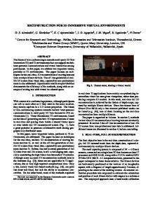
Figure 1: User interacts with a 3D virtual model by using non-instrumented hand gestures c The Eurographics Association 2005. �
Bare hands are the ultimate form of three-dimensional human-computer interface (3D-HCI). The vision guiding the work in this paper is the possibility to perform non-trivial tasks using only a few well-known gestures, so that almost no training is necessary to interact with 3D-software. Today, interfaces of this type still seem to be science-fiction, as they appear for instance in the recent Matrix and Minority Report. In both movies, computers are controlled by pointing with bare fingers at 2D interfaces floating in 3D. This has inspired us to look for what is possible with today’s technology to get as close as possible to such an intuitive an un-instrumented way for operating computers. A less far-fetched and more concrete usage scenario for such kind of technique are 3D shopping terminals, located for instance in shopping malls or in specialized stores. They may be thought of as a generalization of the familiar selling machines with a 2D interface, such as ATMs (for drawing cash money), or terminals for selling railway tickets. Anticipating the increasing use of 3D technology also in the commercial market, easy to use 3D interfaces and applications are mandatory.
192
H. Kim et al. / Tangible 3D: Hand Gesture Interaction for Immersive 3D Modeling
This leads to two fields of research that are tightly related: First, to find the right kind of input device technology, and second, to identify suitable interaction metaphors and devise general design guidelines for responsive 3D applications. This paper presents our first prototype system that integrates both of these aspects, along with the the design decisions and experiences we’ve made. Concerning the interface device, our choice was to use a vision-based tracking approach, based on a pair of cameras with black-light sources. The system has been developed and set up by ourselves, as described in a previous paper [KF04]. It is capable of tracking the fingertips of one hand and also the position of the user’s head. It is used in a passive stereo back-projection environment, so that the user can move freely in a space of approximately (2m)3 . Consequently, the user has a stereo view on the scene, which follows the head position to optimally adapt to the user’s point of view. A typical situation during 3D interaction is shown in Figure 1. This choice of an interface device was motivated by our targeted application scenario. Our main premise is to be as minimalistic as possible on the user requirements (see Figure 5 (c)): We consider a pair of black gloves with bright white marks on the fingertips plus a pair of polarized glasses with a white frame as being quite acceptable, and maybe even mass market compatible, both in price and in practical handling. The stationary system setup is not prohibitively expensive either: Basically a pair of projectors and a pair of cameras are sufficient. Both of these components are currently becoming less pricy through the pressure from the mass market. Concerning our exemple application, our choice was the creation and manipulation of three-dimensional objects, herein referred to as 3D modeling. While this may be an obvious choice for a genuine 3D interface, it has nevertheless turned out to be quite challenging: Controllability definitely is an issue when working in free 3D, without a table to lean on or to guide the user’s movements. Again the reason was to make no assumptions on the physical constraints of our system, and to gain experiences with ’free 3D’.
2. Related Research Interactive 3D modeling is one of the areas where immersive VR can be expected to be most beneficial. There is a trade-off, however, between ease of manipulation and rendering efficiency. One of the crucial ingredients is the choice of a suitable 3D object representation, which must be suited to the target application. See [Kni98] for a discussion of the implications related to the components of a VR system. Implicit surfaces for instance are an example of a model representation with intuitive degrees of freedom [DBW∗ 00, HQ01, DTG96]. But they tend to have slow update rates when the model is interactively changed, due to the fact that the graphics hardware requires a surface to be
tesselated, i.e., converted to triangles, in order to display it. But object representation that require costly pre-processing before they can be displayed are ruled out when interactive update rates are required. Triangle meshes [KBS00] and also point clouds [PKKG03] are routinely used for direct modeling of freeform surfaces. They permit arbitrary surface deformations while maintaining the surface connected or even closed (“water-tight”). Both representations can also work in a multi-resolution fashion, a feature which is indispensable for adaptive real-time display. They have the drawback, however, of being low-level representations: A distinction between different parts of a 3D object on the level of individual points or triangles is difficult. This requires to maintain a segmentation of the surface into different patches. A good compromise are therefore subdivision surfaces, which provide free-form manipulation, have the multi-resolution property, and are also compatible with polygonal meshes. Incidentally there are some modeling systems which contain their own modeling primitives, and allow to create more complex objects by grouping together simpler ones. The drawback is that they are specifically designed for the respective applications [KHK∗ 96, HG96, SIS02]. The usefulness of interaction between user and virtual models is the issue of VR based modelers. Debunne et al. [DDCB01] and Hua et al. [HQ01] use a haptic feedback interface for surface manipulation. Such devices provide the user with the physical feeling of virtual objects, but they generally restrict the available workspace to a desktop environment. VLEGO [KHK∗ 96] and THRED [SG94] use a pair of 6-DOF magnetic trackers (position + orientation data) with additional buttons to issue commands, such as to grab or release the virtual object. These systems support complex modeling tasks by two-handed manipulation, but their input devices are unfortunately less intuitive than a glovetype input device [NUK98]. Schkolne et al. [SPP01] have introduced the Surface Drawing approach for 3D shape creation, which uses a glove-type sensor together with a number of tangible tools: The motion of the hand draws strokes in the 3D modeling workspace, and the thumb activates the creation of a surface. Other tangible interfaces, specifically designed for their respective systems, were also found in [VRCW04, SIS02]. However, to our knowledge, bare hands have rarely appeared in the virtual modeling field, in spite of their high functionality and excellent naturalness, as was noted by Pavlovic [PSH97]. Concerning display devices, head-mounted-display (HMD) can be found more often [KSW00, BO92, FS99] than others, such as a virtual workbench [SPP01, SIS02], or a CAVE [DBW∗ 00]. This may be due to the high usability of the HMDs, which do not require fully equipped display environments. But besides the high price, the drawback of HMD devices is that only one person can follow the interaction. c The Eurographics Association 2005. �
H. Kim et al. / Tangible 3D: Hand Gesture Interaction for Immersive 3D Modeling
193
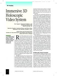
(a) direct hand manipulation in real environment
(b) hand gestures for 3D interactive modeling in virtual environment Figure 2: The five static hand gestures used in our system: Pause, point, grab, rotate, scaling. The gestures mimic characteristic human movements for object manipulation. They are mostly self-explanatory, except for the scaling gesture, which needs to be learned.
3. Hand Gesture based 3D Modeling Focusing on interaction methods for virtual applications in large physical space we find many instances of using computer-vision based techniques. The popularity of this approach comes from the fact that the connection between the user and a computer system is wireless. The unrestrained movement encourages a liberal and intuitive interaction. The fact that the user can freely move on the other hand implies that the gesture recognition must be very robust. The set of meaningful gestures must therefore be carefully chosen so that they can be both issued easily by the user, and robustly detected by the system. 3.1. Gesture Scenario An interaction technique is a method that allows the user to perform some tasks in the system as a part of the user interface. Depending on the application, it supports different modes of interaction, each of them can be issued by a different gesture. Since our chosen application field is shape modeling, the mapping from gestures to interaction modes should mimic the way how hands are used for sculpting and manipulation in the real world. Furthermore, it should support all necessary means for the basic modeling functions through gestures. Hand gestures used for 3D-HCI can be classified into two categories: dynamic gestures and static gestures [PSH97]. Using dynamic gestures generally requires a larger amount of time for training the interaction system, which should also be personalized for each user to get the best recognition performance. Yet our system should also support occasional c The Eurographics Association 2005. �
users. So to keep things simple for the user, we have limited ourselves to a fixed set of five static gestures which are easy to memorize, shown in Figure 2. Another advantage is a reduced processing load for gesture recognition, since in most cases the identical configuration can be used over a number of frames. A typical scenario of using these gestures is the following: Interaction with virtual objects: Pinch the thumb and an another finger after pointing to a target object. The selected objects are manipulated in the same way with the hand motions. • Grab(x, y, z): Close the hand while pinching the thumb and index finger, then move it. • Rotate(x, y, z): Open the hand while pinching the thumb and index finger, and then rotate it. • Scale(x, y, z): Open the hand while pinching the thumb and middle finger, and then move it. Interaction with a virtual cursor: Release the pinching states. This is to handle the cursor of application. • Point(x, y, z): Close the hand except for the thumb and index finger, which points straight at the target object. This orders a cursor to move to the position indicated by the index finger. • Pause(x, y, z): Open the whole hand. VR applications have to support four main categories of interaction tasks: navigation, selection, manipulation, system control [BKL∗ 00]. Table 1 shows the commands supported by our hand gestures. System control is achieved through a graphical 3D menu, which is operated in the same
194
H. Kim et al. / Tangible 3D: Hand Gesture Interaction for Immersive 3D Modeling
(a)
(b)
(c)
(d)
Figure 3: Hand gesture interaction: (a) object manipulation and deformation by (b), (b) the sequence of gesture interaction – pause, point(object), rotate, translate (z-direction), point(object’s vertex), translate(object’s vertex), and rotate, (c) object creation from a simple primitive by (d), (d) the shape design drawn along the hand movement
Selection Manipulation
(Point(x, y, z) or Pause(x, y, z)) + (Grab(x, y, z) or Rotate(x, y, z)) Translation Grab(x, y, z) or Rotation(x, y, z) Rotation Rotate(x, y, z) Uniform scaling Scaling(z) Table 1: Interaction tasks
6DOF manipulation and selection, our gesture commands include scaling function as well, which is useful especially for shape modeling. It is triggered by pinching the thumb and middle finger, while pinching the thumb and index finger goes into rotation. The use of different pinching combinations shows the possibility of extension of the gesture set if necessary. 3.1.1. Visual feedback
way as object selection (see section 3.3), namely by pointing. Navigation is done mainly via head tracking (see section 4.1.3). All gestures are associated with a 3D position, which can obviously be changed by moving the hand. So the rotate gesture can simultaneously be used to translate an object. One crucial point in designing interaction modes is to take into account the limited freedom of movement of the different parts of the human body. Especially the hand can only perform limited rotations, so it is important to allow absolute as well as relative motions. Consequently, our system allows for cumulative rotations by repeating rotate-and-pause gestures. In addition to the basic 3D interaction functionalities of
To control graphical objects the user ’touches’ them with the interaction interfaces. Without the physical collision, however, it is not easy to perceive the distance between the interface and the targets. To reduce the user’s cognitive load, our modeler provides a number of different gizmos, proxy objects which are occasionally set into the scene as visual feedback clues. Gizmos are not part of the 3D model, but serve as a visual representative for a particular operation, to indicate a specific mode, or to give information about the status of the interaction. The great advantage of gizmos is that they also improve the robustness of the interaction tasks: Certain modeling operations become much more controllable if they are not directly issued by gestures, but indirectly: The gizmo is manipulated by gestures, and the gizmo in turn issues the modc The Eurographics Association 2005. �
H. Kim et al. / Tangible 3D: Hand Gesture Interaction for Immersive 3D Modeling
eling operation, so that it is executed in a more controlled way. One simple example is the arrow-shaped model which is used as a 3D cursor to represent the user’s hand in 3D virtual space. The position of the arrow is determined by the projection of the user’s hand position in real space to the virtual 3D scene. So it is always in front of the scene, and it works like the familiar 2D mouse pointer on a 2D desktop. When there is a collision between the arrow cursor and a target object, another gizmo like a control ball or an object bounding-box appears. For other tasks such as rotating or twisting objects, a tripod gizmo with three coordinate axes is drawn, which moves in correspondence to the user’s hand orientation. 3.2. Modeling Operations Figure 3(a-b) illustrates some deformations of a 3D object together with the corresponding gestures used in the each step. The respective gestures in the hand-motion sequences also indicate the required modeling operations for the steps, as they correspond a direct manipulation tool for creating or modifying 3D shapes. 3.2.1. Shape Representation The basis of the modeling operations is a mesh data structure for interactive 3D design and manipulation, the Combined BRep (CBRep). It supports incremental on-line update and adaptive rendering through a multi-resolution tesselation [HF04]. The special feature of Combined BReps is that they bridge the gap between polygonal and free-form models. The mesh is an ordinary polygonal mesh by default, but any part of the mesh can also be used as the control mesh of a Catmull/Clark subdivision surface. So a CBRep mesh can have both smooth free-form and polygonal parts, with crease curves establishing a link between them. Both types of geometry are integrated in a single data structure by associating a boolean sharpness flag with each edge, to distinguish between sharp and smooth edges. In regions with only sharp edges, BRep faces are triangulated, just as with standard polygonal meshes, whereas in smooth regions, the tesselation is created using recursive subdivision. By just changing the sharpness flag, it is possible to switch between both representations: Any face that contains at least one smooth edge is treated as a Catmull/Clark surface (see Figure 4). Combined BReps are optimized not only for real-time rendering, but they can also accommodate for changes of both the vertex positions and the mesh connectivity in real-time, by incrementally updating the changed parts of the tesselation. The availability of CBReps was the basis of the plan to realize a 3D modeling application which made use of our vision based tracking system as an intuitive input device. One important lesson learned was that the existence of a control c The Eurographics Association 2005. �
195
Figure 4: Face representation change by seting the sharpness flags of the edges (from sharp to smooth)
mesh greatly improved the controllability of surface manipulation: Distinct graphical feedback can be given to the user who is going to manipulate either a vertex, an edge, or a face of the control mesh. The mesh as intermediate structure also facilitates the selection of specific parts of the object (surface navigation), and has proven less tedious than a direct manipulation of the many triangles from the tesselation via gestures. Our model data are maintained in the Wavefront .obj file format, thus the input/output objects can be compatibly shared with other modeling products supporting this popular format. 3.2.2. Selection The pointing approach [VdPRHP99] is used for target selection. Note that only visible targets in the user’s field of view can be candidates for selection. But since our system supports head tracking (see section 4.1.3), it allows to change between different views in a natural way, and unselectable targets in one view may become selectable in another. This approach is advantageous because: - In most cases, an occluded object can be selected without actually removing the objects obstructing it. This possibility depends of course on the nature of the scene, and works best with scenes that are not too ’opaque’. - The target must be searched only in 2D, not in 3D. This enables the use of fast screen-space selection methods, which accelerates the selection of very distant objects. Smooth parts in our model are represented in Catmull/Clark subdivision surfaces. The individual triangles of the tesselation usually cover only a few pixels, so there are obvious difficulties to accurately intersect a specific triangle by a ray shot from the tracked head position through the tracked position of the pointing finger. The solution is to restrict the selection to the vertices, edges, and faces of the control mesh, which are much easier to uniquely identify – both for the user and for the system. 3.2.3. Navigation The size of the work space in front of the projection screen is limited by the viewing angle of the cameras used to track
196
H. Kim et al. / Tangible 3D: Hand Gesture Interaction for Immersive 3D Modeling
(a)
(b)
(c)
(d)
Figure 5: System environment: (a) back-projection screen, (b) two projectors for passive stereo, (c) user interfaces – white paper-rimmed polarized glasses and fingertip markers (d) a black light
the user’s motion. In particular, it is not possible to walk completely around a 3D object, so it must be possible for the user to navigate within the scene. In interaction mode, we therefore provide the usual possibilities of translation and zooming supported by head tracking (see section 4.1.3), as well as the rotation around a particular target (’orbit’). In addition to this, objects can be moved in the scene. Target selection is done as usual, by pointing. 3.2.4. Global vs. Local Deformations By moving individual vertices and faces of the mesh, the user has fine-grained local control about the shape. But the shape is not only defined by the position of the vertices, but also by the connectivity of the mesh – as the case with all surface types based on subdivision. So to allow for controlled changes of mesh connectivity, we have added the Euler operators to the set of manipulation modes. Specifically, the user can - insert an edge to split a face in two, - insert a new vertex on an edge, - and split a vertex in two, connected by a new edge. It should equally be possible to smoothly deform larger parts of the mesh, which involves moving a number of mesh vertices. We have therefore adopted the Twister approach from Llamas et al. [LKG∗ 03] to use it with Combined BReps. It works by applying a smooth space warp to all vertices inside a spherical region of influence of adjustable radius. So the user first selects a warping-region including several vertices on the control mesh of a model, and moves it then to a new position, with the hand rotating in order to tilt, bend, or twist the shape. Since this can have drastic effects on the global shape, this method is quite sketchy and suitable for simulating the spatial deformation of a rubberlike material. It is less applicable though for obtaining precise results, and is not suitable for CAD-like construction tasks.
3.3. Changing the modeling mode The modeler needs to support various useful operations in terms of the system productivity. Using many kinds of gestures for each operation however can easily overloaded the user with a large amount of the gesture learning. Providing a graphical menu can be the suitable solution for changing the operation modes, instead of developing new gestures or adding second interfaces. This is attributable to the fact that users in general already have rich experiences and skills in using menus and windows. The menu is placed on the boder of the scene, typically considered as the ’dead space’ of the screen. The user can choose the operation by using the hand gestures, like selecting a model object.
4. System Setup The hardware of our modeling environment consists of a passive stereo back-projection display with two projectors, one PC to run the vision tracking software, and another PC to run the modeling application. Both computers are connected via standard ethernet.
4.1. Camera/Vision tracker The space in front of the back-projection screen (about 2.5m × 2m × 2m) is the work space for interaction. This volume is typically of sufficient size for any kind of modeling application. The cameras are mounted near the upper edge of the screen, covering the interaction area but not limiting the movement of the users. 4.1.1. Interaction environment setup The projection display environment usually involves a dim light condition to achieve a high-contrast screen projection. On the other hand the screen emits a variable amount of c The Eurographics Association 2005. �
H. Kim et al. / Tangible 3D: Hand Gesture Interaction for Immersive 3D Modeling
light, so it is not feasible for the vision-based tracking to assume a static lighting condition. Variable lighting can deteriorate the quality of the images captured by a camera, which in turn affects the image processing, and thus the results for tracking features in the images. To solve these problems we use a ’black-light’ [Rye96] source and white paper markers on the fingertips: The black light stimulates enough fluorescent emission from the white paper markers to distinguish the detection features even on the low-contrast camera image. Since the black light is barely visible, it hardly influences the projection quality, and only the markers are highlighted [KF04]. Using white paper as a marker material has obvious advantages: it is readily available, of low cost, and of light weight. Since the black light illuminates a white Tshirt in the same way it illuminates the white paper, this approach however builds on the assumption that users do not wear white clothes or reflective accessories. 4.1.2. Interface design In order to let a user’s field of view cover the whole screen, the user generally keeps the adequate distance to the screen. Symmetrically, the cameras and the user’s hand are at the same distance, which may reduce the details of the tracking features to a limited image resolution. So, if a hand is marked with too many markers, segmenting each marker will cause problems. Therefore we limit the number of markers to only four. While a user performs an interaction, the postures and positions of the hand will be continuously changed and updated. Though the unrestricted motions are desirable for a natural interaction, it often can cause some difficulties such that the markers turn away from the camera view. To compensate this we experimented with different marker arrangements with respect to shape and position. When ring shaped markers are placed at finger joints, the distance between markers was too short to distinguish them reliably. In motion they also might get lost due to occlusion by the fingers themselves. As a consequence, our markers are placed on the fingertips (thumb, index, middle and little finger) which are less frequently occluded, compared to other parts of the hand. A marker is designed like a thimble to fix easily to the fingertips. This compact shape can allow comfortable and natural motion according to our experience. For the head tracking interface, the polarized glasses is rimmed with white paper. Figure 5(c) shows the thimbleshaped fingertip markers and the white paper-rimmed polarized glasses.
197
frame the center of the pair of glasses is computed. The left and right eyes are assumed to be 3 cm to the left and to the right of the center of the glasses. We use linear polarizers for passive stereo, where the light for one eye is polarized perpendicular to the light for the other eye. It means that the users must keep their head level or they will lose the stereo effect as the polarization of their stereo glasses no longer matches that of the projector filters. So only the position of the head is needed. These positions establish the two viewpoints for the stereo rendering. Figure 6 shows the typical scenes generated from the tracking of the head. 4.2. Network Connection The whole system can be roughly divided into two parts: the modeling system and the tracking system. They are connected via our standard ethernet network. The tracking system executes the computer-vision algorithms to monitor the gestures of the user’s hand, and the position of the head. This information is sent to the second component, the modeling system, for viewpoint maneuvering and object interaction. The transmission of the data from the tracking system to the modeling system is done via TCP/IP packets containing the description of user motion. To maintain a nearly real-time communication the send-receive procedure works in its own thread on both machines, so that it is independent from the rendering of the scene. 5. Experimental Result We have developed the modeling system on an AMD Athlon XP 2200+ PC with 512 MB of RAM and a GForce4 TI4600 graphic card (128 MB). This platform provides real-time updates (about 30 − 50 frame/sec) of stereo scene projection. The camera/vision tracker runs on an AMD Athlon XP 2000+ PC with a DFG/BW-1a frame grabber board and two SONY XC-55 progressive scan cameras, with 30 frame/sec in average to track the user’s head and hand simultaneously. The rendering frame rate and the scene quality is dominated by the model complexity and the tessellation update on shape deformation. To generate smooth and natural animation while modeling, the scene rendering always has higher frequency than the data transmission from the tracking system.
4.1.3. Head tracking
The power as a virtual modeling system can be evaluted by the performance of building 3D models through the given interaction interfaces, hand gestures in our case. It is closely related with and mainly depends on harmony between the interaction method and interactive model representation.
Eye positions are needed in order to generate accurate stereo views according to the user’s perspective. However, because the user wears stereo glasses, the actual eyes are not visible and cannot be tracked. So we approximate the eye positions by the positions of the glasses on the head. First, we set up the polarized glasses as a second tracking target. In each
First, the gesture-based interaction could instantly lead to the understanding of each gesture from the users after a short explanation. They could easily make a set of gestures with their hand and invoke the reaction from the system. The case of medium level of modeling work could be quickly realized as well. For more demanding operations such as ’shape
c The Eurographics Association 2005. �
198
H. Kim et al. / Tangible 3D: Hand Gesture Interaction for Immersive 3D Modeling
Figure 6: Viewpoint movement by head tracking
design’, we noticed that it needs somewhat more training to produce the intended results right away. Figure 7 (a-e) show some results produced by one of the authors, to represent our model creation in gesture drawings. It was certainly effective for wide range of shape sketching and modeling. The time spent to get simle models like question mark, alphabet characters and flower did not exceed 1-2 minutes, since they were simply drawn along the path of hand movement in space. The model in Figure 7 (c) is from 3D croquis drawing made in a few minutes through similar manner to draw on paper with a pencil. Not only the smooth shapes, but also the polygonal forms could be achieved just by changing the sharpness flag of edges in the control mesh. Figure 7 (f) shows a short process of model generation, starting from cubical primitives to more refined form. Once the source object was prepared, the other deformation operators were used for refining or modifying the model. Figure 7 (a), (d) are the examples of a bit more complex shape creation followed by additional modeling operations. The tree object in Figure 7 (g) is one of the example models with a complex geometry and a large number of small polygonal facets. The detail control for this kind of models, such as editing the end of each twig, was quite difficult without any haptic feedback. In this case the extensive deformation operator like a simultaneous control of multiple vertices was certainly useful. More advanced shape editing were demonstrated in Figure 7 (h-j) shape tilting and bending. As these experiments indicate, the modeling system could easily and quickly reproduce the shapes of the existing objects by the hand gestures. The results obtained so far are quite promising. In the near future, we will therefore perform systematic usability studies with larger groups of untrained users. We hope that an analysis of the user feed-back will reveal which of the proposed modeling methods works best for which kinds of application scenario. 6. Conclusions and Future Work Hand gestures have proven a very expressive, convenient, and robust tool, and they have quickly become a popular
’workhorse’ for intuitive 3D manipulation in our group. But gestures alone do not make for a complete system. Our interaction interface builds upon three components that are used in conjunction: a) hand gestures, b) gizmos as virtual controller objects, and c) textual menus for mode changes. Our experience so far has revealed that the real power of ’tangible 3D’ is unleashed only by an intimate fusion of all components. Users are enthusiastic about the ’hand-asa-tool’ metaphor, but the controllability and the precision of the interaction must still be improved. So our future plans are to even better integrate the different methods: Examples include using gestures for mode changes on a per-gizmo basis, written annotations everywhere to clearly flag the current mode states, numeric measurements producing ’tangible values’ that can be put on a shelf, or used as input values for other operations, and many more. Our focus is, and will be, on building a generic infrastructure for direct, semi-immersive 3D interaction. We believe our system has distinguished advantages: It is quite affordable, actually, and its performance will improve with increasing computer, e.g., recoginition, power. The key component for making the step from laboratory to field application though is the software. Our goal is a software interface that permits to easily transfer any given 3D application to such a tangible modeling space, by wrapping its functionality using gestures, gizmos, and floating text. This will ultimately give creative people a new media at hand, to use it in fields such as arts, industrial design, and architecture.
References [BKL∗ 00] B OWMAN D., K RUIJFF E., L AV IOLA J., P OUPYREV I., M INE M.: The art and science of 3d interaction. Tutorial Notes from the IEEE Virtual Reality 2000 Conf., IEEE Computer Society (2000). [BO92]
B UTTERWORT J. D. A. H. S., O LANO T.: 3dm: c The Eurographics Association 2005. �
H. Kim et al. / Tangible 3D: Hand Gesture Interaction for Immersive 3D Modeling
A three dimensional modeler using a head-mounted display. Computer Graphics. In Proc. of Symposium on Interactive 3D Graphics 25(2) (1992), 135–138. [DBW∗ 00] D EISINGER J., B LACH R., W ESCHE G., R. B., S IMON A.: Towards immersive modeling - challenges and recommendations: A workshop analyzing the needs of designers. In Proc. of the 6th Eurographics Workshop on Virtual Environments (2000). [DDCB01] D EBUNNE G., D ESBRUN M., C ANI M., BARR A.: Dynamic real-time deformations using space and time adaptive sampling. In Proc. of SIGGRAPH’01, ACM Press (2001), 31–36. [DTG96] D ESBRUN M., T SINGOS N., G ASCUEL M.: Adaptive sampling of implicit surfaces for interactive modelling and animation. Computer Graphics Forum 15(5) (1996), 319–327. [FS99] F UHRMANN A., S CHMALSTIEG D.: Concept and implementation of a collaborative workspace for augmented reality. GRAPHICS ’99 18(3) (1999). [HF04] H AVEMANN S., F ELLNER D.: Progressive Combined BReps - Multi-Resolution Meshes for Incremental Real-time Shape Manipulation. Tech. rep., Institute of Computer Graphics, TU Braunschweig, 2004. [HG96] H ALLIDAY S., G REEN M.: A geometric modeling and animation system for virtual reality. Communications of the ACM 39(5) (1996), 46–53. [HQ01] H UA J., Q IN H.: Haptic sculpting of volumetric implicit functions. In Proc. of the 9th Pacific Conference on Computer Graphics and Applications (2001), 254–264. [KBS00] KOBBELT L. P., BAREUTHER T., S EIDEL H.P.: Multiresolution shape deformations for meshes with dynamic vertex connectivity. Computer Graphics Forum 19, 3 (Aug. 2000), 249–260. [KF04] K IM H., F ELLNER D.: Interaction with hand gesture for a back-projection wall. In Proc. of Computer Graphics International (2004). [KHK∗ 96] K IYOKAWA K., H ARUO T., K ATAYAMA Y., I WASA H., YOKOYA N.: Vlego: A simple two-handed modeling environment based on toy blocks. In Proc. of ACM Simpo. on Virtual Reality Software and Technology (VRST’96) (1996), 27–34. [Kni98] K NIGHT C.: Virtual reality for visualisation. Technical Report 13/98, Department of Computer Science, University of Durham (1998). [KSW00] K AUFMANN H., S CHMALSTIEG D., WAGNER M.: Construct3d: A virtual reality application for mathematics and geometry education. Education and Information Technologies 5(4) (2000), 263–276. [LKG∗ 03] L LAMAS I., K IM B., G ARGUS J., Twister: A spaceROSSIGNAC J., S HAW C. D.: warp operator for the two-handed editing of 3d shapes. c The Eurographics Association 2005. �
199
ACM Transactions on Graphics 22, 3 (July 2003), 663–668. [NUK98] N ISHINO H., U TSUMIYA K., KORIDA K.: 3d object modeling using spatial and pictographic gestures. In Proc. of the ACM symposium on Virtual reality software and technology (1998), 51–58. [PKKG03] PAULY M., K EISER R., KOBBELT L. P., G ROSS M.: Shape modeling with point-sampled geometry. ACM Transactions on Graphics 22, 3 (July 2003), 641–650. [PSH97] PAVLOVIC V., S HARMA R., H UANG T.: Visual interpretation of hand gestures for human-computer interaction: A review. IEEE Transaction on Pattern Analysis and Machine Intelligence 19, 7 (1997), 677–695. Light measurement handbook. [Rye96] RYER A.: http://www.intl-light.com/handbook/ (1996). [SG94] S HAW C., G REEN M.: Two-handed polygonal surface design. In Proc. of ACM Symposium on User Interface Software and Technology (1994), 205–212. [SIS02] S CHKOLNE S., I SHII H., S CHROEDER P.: Tangible + virtual = a flexible 3d interface for spatial construction applied to dna. CS TR 2002.011, California Institute of Technology (2002). [SPP01] S CHKOLNE S., P RUETT M., P. S.: Surface drawing: Creating organic 3d shapes with the hand and tangible tools. In Proc. of CHI 2001 (2001), 261–268. [VdPRHP99] VAN DE P OL R., R IBARSKY W., H ODGES L., P OST F.: Interaction in semi-immersive large display environments. In Proc. of EGVE ’99 (1999), 157–168. [VRCW04] VANDOREN P., R AYMAEKERS C., C ONINX K., W EYER T.: Two-handed interaction inspired by tangible interfaces in 3d modelling. In Proc. of 15th IASTED Modelling and Simulation Conference (2004), 197–202.