This drives up the software development cost and effort and is not scalable ... application are compiled together to create a monolithic executable. It supports an ...
Tapper: A Lightweight Scripting Engine for Highly Constrained Wireless Sensor Nodes Qiang Xie, Jinfeng Liu and Pai H. Chou Center for Embedded Computer Systems, University of California, Irvine, USA {qxie, jinfengl, phchou}@uci.edu
ABSTRACT Tapper is a lightweight scripting engine for highly constrained wireless sensor nodes. Many such nodes run on 8-bit microcontrollers (MCUs) with only a few kilobytes of on-chip memory, often with segmented memory and unorthogonal registers that make it difficult to perform even the most basic tasks. To facilitate development of software routines and enable dynamic reconfigurability, Tapper provides a software layer that can interpret human readable commands either interactively or in batch. It can invoke compiled routines ranging from timer and interrupt configurations and task scheduling to accessing I/O devices. Experiments on platforms including 8051, ATMega 169V, and Freescale MC9S12NE64 with built-in Ethernet show that the Tapper setup has the same modular, dynamic benefits as middleware systems but without the high overhead in code size and data memory.
Categories and Subject Descriptors D.2.6 [Software Engineering]: Programming environments—Interactive environments
General Terms Design, Languages
Keywords Scripting, resource constrained systems, scripting engine, test and debugging, reprogramming, wireless sensor platform
1.
INTRODUCTION
Emerging applications are driving the trend towards heterogeneous, distributed and networked sensor systems with dynamic configurability and interoperability. Wireless sensing nodes with a wide range of form factors, costs, and capabilities have become available and are actively being developed. On the high end, such a platform may be a pocket computer with 64MB RAM and a 400MHz processor running Linux. On the low end, it may be a miniature sensor node with an 8MHz 8-bit microcontroller (MCU)
Permission to make digital or hard copies of all or part of this work for personal or classroom use is granted without fee provided that copies are not made or distributed for profit or commercial advantage and that copies bear this notice and the full citation on the first page. To copy otherwise, to republish, to post on servers or to redistribute to lists, requires prior specific permission and/or a fee. IPSN’06, April 19–21, 2006, Nashville, Tennessee, USA. Copyright 2006 ACM 1-59593-334-4/06/0004 ...$5.00.
and 1KB RAM. In addition to interoperability, new applications also demand adaptivity and in-field programmability. Unfortunately, designers today are still taking the same singleprocessor, platform-specific approach to the development of these distributed systems in ways essentially unchanged for the last several decades. That is, they manipulate architecture specific-registers for low-level configuration and control of interrupts, I/O, and power. This drives up the software development cost and effort and is not scalable, and interoperability is often added as an afterthought. Although middleware has been proposed for larger systems, the high memory and computational requirements make it impractical to many low-power, memory-constrained miniature sensor nodes. However, given that memory is one of the largest energy consumers that must stay on more often than RF, many wireless sensor nodes cannot afford to have a memory larger than a few kilobytes. Our approach is to collapse the thick layers of software into a lightweight scripting engine called Tapper. It interprets a small command language either interactively or in batch. The language corresponds to system services including real-time and power control as well as standard, extensible communication primitives. We make the observation that all nodes in a wireless sensor network must exchange messages, as all distributed systems must be able to handle, and scripts can be viewed as a generalized communication message format. Thus, the overhead incurred by Tapper is quite marginal. A scripting architecture for distributed sensor systems will have the same modular, dynamic benefits as middleware systems but without the heavy marshalling and demarshalling runtime overhead. More importantly, the platform-independent subset of scripts will enable seamless interoperability among a wide range of systems from the smallest of sensor nodes to large-scale, highperformance, general-purpose computing systems that can assist small systems with processing and optimizations. Tapper has been applied to a variety of wireless and wired sensor platforms with a wide range of MCU architectures and communication capabilities. It runs comfortably on an ultra-compact, lowpower wireless sensor called Eco with an 8051 compatible core and 4K shared program/data RAM. The same scripts also run on an AVR ATmega MCU with 1K RAM but more I/O devices as well as a Freescale 16-bit MCU over a TCP/IP protocol stack, and it can be ported to any general purpose computer. The ability to issue commands to Tapper interactively is very helpful during software development and in-field diagnosis. The ability to load different scripts for batch execution makes these systems evolvable. These benefits are expected to make Tapper an attractive software platform for a wide range of increasingly heterogeneous networks.
2.
BACKGROUND AND RELATED WORK
Although it is possible to implement resource-constrained em-
Table 1: Comparison of different software architectures Name TinyOS with Deluge SOS Mat´e VM VM? Tapper
Code Size 21.1KB 20.4KB 39.7KB 8KB 3KB−11KB
Data Size 597B 1.1K−2.7KB 3196B 1.5KB 230B −1.5KB
App. Update High Medium Low Medium Low
TAPPER SOFTWARE ARCHITECTURE
Tapper features a scripting engine built on top of a set of low level application programming interfaces (APIs). The lightweight scripting engine parses human readable scripts and invokes system services supported by the underlying hardware platforms. This section briefly discusses the scripting language, followed by a description of the services provided by Tapper.
Require OS − − Yes Yes No
Scripts Command Command Buffer Manager
Script Interpreter
Command string:
X5{RS 101 hi; X10{A3; A4; A5}}
System Primitives Timer GPIO SPI
18
10
3
5
..…
3.
Dynamic Kernel Update No Yes No Yes No
..…
bedded sensor systems without runtime support, several runtime systems have been proposed to support programming abstractions and configuration. TinyOS [5] is the most widely used system, where the software components including runtime support and the application are compiled together to create a monolithic executable. It supports an event-driven programming model with low runtime overhead. However, the compiled approach makes it rigid, not easily evolvable, and not interactive accessible. To address the problem of code update, the Deluge [6] component for TinyOS supports post-deployment system reprogramming by enabling updating of binaries. TinyOS2 supports postdeployment writing of selective executable code into the program memory. However, in the case of heterogeneous networks, different binaries must be generated for each configuration. In all of these compiled approaches, pre-deployment testing is difficult. It would require either a simulator that does not have access to the actual I/O, or an in-circuit emulator (ICE) that may be too bulky to test in its intended deployment site. In SOS [4], applications are written in standard C and compiled to modules that can be added to or removed from the system. The dynamically uploadable modules include not only application code but also system services. To support interactive access, design-time abstractions, testing support, and post-deployment updates, a variety of interpreters, middleware, and virtual machines have been proposed. Mat´e [8] is a bytecode interpreter built on top of TinyOS and occupies 16.8KB memory. Its bytecode is for low level operations for a stack machine, though they allow eight user-defined instructions. The support for scripting is thus limited. VM? [7] is a Java interpreter with support for updating both the application and the system software. However, its interpretation overhead can be very high; it does not support interactivity, and it needs support from an underlying operating system, OS? . Table 1 compares these different software architectures. Tapper differs from them in several ways. First, it supports a wider range of hardware platforms, from simple, 8051-based MCUs to 16-bit MCUs with TCP/IP over Fast Ethernet and much larger ones. Second, the lightweight scripting engine can be synthesize to explore a wider range of implementation options, ranging from extremely lightweight to arbitrarily complex, depending on the application requirements and resource constraints. Third, Tapper is a stand-alone software architecture that encompasses both the runtime support and the interpreter. This is in contrast to other virtual machines or middleware layers that run on top of some other runtime system.
App. Development NesC C human readable script Java human readable script
Address
Operand
Stack
Stack
…
Tapper Kernel
(a)
(b)
Figure 1: (a) Tapper architecture (b) Address & operand stack
3.1
Scripting Language
Scripting refers to the interpreted execution of a script program that defines the invocation order and condition of software components, plus data buffers that connect them. Scripts tend to be much easier and shorter to write and understand than the equivalent program in system programming languages such as C and Java [11]. In Tapper, a command is a string with keywords and values in a syntax. A script is a string that contains a sequence of commands. Table 2 shows the set of commands on Eco platform. These commands provide system calls to primitives that access the hardware devices such as ADCs and RF transceivers, and system control such as repeating or resetting. They are concise, short, and easy to understand, enabling users to learn in minutes. These commands enable Tapper to provide a common abstraction of hardware resources over heterogeneous platforms.
3.2
Tapper Kernel
The Tapper kernel consists of a command-buffer manager, a lightweight script interpreter, and the low-level system primitives, as shown in Fig. 1(a). The command-buffer manager maintains a buffer to store user input scripts, and the script interpreter parses commands and invokes the corresponding system services supported by underlying hardware platform. The system primitives, such as AD conversion, are platform dependent and must be implemented on each platform separately, but their APIs to the script interpreter are fixed for all platforms. Therefore, the same script interpreter can be made easily portable to different platforms as long as the low-level primitives are well-defined and correctly implemented.
3.3
Scheduling Services
The command-buffer manager stores a script as a list of commands in a FIFO command queue. This provides a very simple and efficient scheduling service. In addition to the sequential execution, Tapper supports simple interleaved parallelism by using the timer channels on the MCU. MCUs normally include several software programmable timers, and user scripts can be scheduled to execute during the timer in-
foo1
unsigned char timer_0_func = 0; void Timer_0_Interrupt(void){ switch(timer_0_func){
Host +foo1
Target Memory Manager
Target w:x:(….)
Host foo1
Memory x
foo1
Target Memory Manager
Target e:x:len
Memory x len
case ‘A’:
(a)
cmd_run_adc();
(b)
break;
Figure 3: (a) Writing scripts (b) Invoking scripts
case ‘I’: cmd_get_input();
char timer_0_buf[BUF_LENGTH];
break;
void Timer_0_Interrupt(void){ cmd_intepreter(timer_0_buf);
} }
}
(a)
(b)
Figure 2: Comparison of two implementations of timer interrupt function: (a) Direct call(b) Indirect Call through interpreter
terrupt. For example, the command “T50{A2}” means to sample ADC Channel 2 every 50ms. Upon detecting a new command with a timer request (i.e., the symbol “T”), the interpreter first checks if timer channels are available. If so, then the interpreter initializes a timer and sets its interrupt handler to be the primitive to be scheduled. In the above example, that primitive is the ADC routine. If all timer channels are busy, then the interpreter will return an error message. The user can also remove a script from the schedule. For example, “K2” will kill the scripts executed on timer channel 2 by disabling the interrupt. Two methods are applied to implementation of the timer interrupt handler. One way is to use a global variable for each timer channel. This timer function variable represents the current executed primitive of the timer. In the timer interrupt handling routine, it checks this variable to determine which primitive will be called, as the example shows in Fig. 2(a). The variable is a character-type quantity that occupies 1 byte of memory. This method directly accesses pre-installed system primitives. So, it is fast, easy to implement, and requires minimum memory space. However, the primitive to be called has to be compiled with the kernel. Also, only one primitive may be called during the interrupt. This limits the flexibility to schedule other tasks. An alternative way is to allocate a buffer to store user scripts for each timer channel. At run-time, user-defined scripts will be written to these buffers. The timer interrupt handling routine will fetch the commands from its corresponding buffer and call the script interpreter to parse and execute the command, as the example shows in Fig. 2(b). This method provides the user with a more flexible way to dynamically schedule a periodic task in the sensor node. The drawback is that it incurs additional overhead by sending commands to the interpreter. Another problem is that extra data memory space is required to store scripts. The size for the buffer should be carefully considered based on available memory space.
3.4
Loop Execution
For Tapper to support a simple loop execution mechanism, it maintains an address stack and an operand stack for the execution of loop command “X”. The address stack is used to store the index of the first character inside the block of the script, and the operand stack is used to store the repeat count of the block. Fig. 1(b) illustrates the loop execution sequence. There are two blocks in the script, marked by “{” and “}”. Upon executing the first block, the interpreter first pushes the operand of the command “X”, representing the repeat count (which is 5), to the operand stack, and the index of the first character of that block to the address stack. During execution of the first block, it meets another
repeat block. Similarly, the operand 10 is pushed onto the operand stack, and address 18 is pushed onto the address stack. The interpreter starts parsing commands from the second block until it reaches “}”, which marks the end of a block. The repeat count on top of the operand stack is decremented by 1. If it is not zero, then the interpreter parses the command whose address is on top of the address stack. If the operand on top of the operand stack is zero, then the operand and address are popped off their respective stacks. The interpreter continues executing the first block until it reaches the end. Then, the repeat count of the first block, which is on top of the stack now, is decremented by 1, and the interpreter checks this value to decide whether to repeat the first block.
3.5
Reprogramming & Memory Management
A distinguishing feature of our approach is host-assisted reprogramming and memory management. That is, the host computer maintains the knowledge about data and program memory usage on the node. The host translates the memory management actions into a sequence of lower-level primitives implemented on the node. This way, the node complexity is kept low. To accomplish the hostassisted operations, Tapper takes advantage of the Rappit framework [3]. Rappit provides a command line interface that intercepts and preprocesses all commands before sending them to the node. Fig. 3 illustrates the process of reprogramming and executing a new script. Reprogramming the sensor system is performed by writing the new scripts into the target system’s data memory (Fig. 3(a)), which may be RAM or data flash. A new script has a name, such as “foo1”, and the user adds it using the “+” command (e.g., by typing “+foo1”) on the host. To recall, the host runs the Rappit framework to assist reprogramming and memory management by maintaining a memory map of the target system. When Rappit parses the “+” command, it passes the command to the memory manager. The memory manager calculates the length of the script and allocates the corresponding memory blocks for it. The “+” command then is translated to the memory write command “w:x:...”, where x is the start address of the allocated memory. After allocating memory to a new script, the memory manager records the script’s name, starting address, and length in a table, When calling a script (e.g., “foo1”), the host computer looks up its name and translates it into executing memory command “e:x:len”, where x and len are the start address and length of the script respectively, as shown in Fig. 3(b). The memory space of our sensor node consists of SRAM and flash memory. A portion of the memory, called the scripts memory, is configured to store scripts. The memory manager mainly maintains the scripts memory for each sensor node in our current implementation, though ongoing work is extending it to managing data memory as well. It maintains a free memory list and the usage frequency of each block. In response to a “+” request, the memory manager attempts to allocate memory from the free list. If there is not enough free memory, then it will de-allocate some of the occupied memory space based on their usage frequencies. In both cases, the memory manager on the host expresses the allocation scheme in terms of memory access primitives to be executed on the node.
Table 2: Tapper commands on Eco platform Command A[ch] E:[addr]:[len] D[n] RA[c] [freq] RI[p f c w m] RS[c] [str] RR[ch] RL SET m.para(val) T[N]{block} X[N]{block} W:[addr]:block !H/S +[func] −[func]
Description Reading ADC channel ch Fetch len bytes data from address addr and execute it Delay n ms Read ADC values and send data via RF channel c at frequency freq RF Init/Info RF send via channel c RF receive from channel ch RF Listen Configure module m’s parameter para as val Repeat block in {} every N ms Repeat block in {} N times Write block to memory address starting at addr Hardware/Software reset Upload function func to target system Remove function func from target system
Example A1; A2 E:f000:5 D100 RS 101 Hi RI 4 1 2 3 T RS 101 Hi RR2 RL SET TIMER1.PERIOD(1000) T5{A2} X5{RS 101 Hi} W:f000:PG0=1 !H; !S +foo1 −foo1
abstraction for developing applications.
4.2 (a)
(b)
(c)
Figure 4: The Eco wireless sensor platform: (a) Eco on an index finger (b) Eco vs. Mica2DOT (c) Eco top view.
4.
EXAMPLE: TAPPER ON ECO NODE
This section describes implementation details of Tapper in the context of an ultra-compact wireless sensor node named Eco [14]. As shown in Fig. 4, only 648 mm3 in volume and weighing under 1.6 grams, Eco was initially designed to monitor the spontaneous motion of pre-term infants for their growth. Eco nodes are also highly suitable for many real-world applications, including environmental monitoring, new computer-human interface, ambient intelligence, and interactive art performance [13].
4.1
Eco Hardware Architecture
An Eco node consists of an nRF24E1 [10], a chip antenna, a 32K external EEPROM, a tri-axial accelerometer and temperature sensor, a light sensor, and a lithium polymer battery. The nRF24E1 is an 8051 MCU core with built-in I/O resources including a 2.4GHz RF transceiver, one SPI, one RS-232 port, and a 9-channel AD converter. The user program is stored in the 32K EEPROM and loaded through SPI. The latest Eco also features an expansion port that makes these I/O pins accessible to the end user for interfacing with other types of sensing devices such as a camera, joint angle sensor, and more [12]. The transceiver on the nRF24E1 uses a GFSK modulation scheme in the 2.4GHz ISM band. It can choose from 125 frequency channels that are 1MHz apart, and it can transmit at up to 0dBm at a data rate of 1Mbps. The RF output power, data rate, and frequency are all software configurable. Eco is highly memory constrained. The MCU has 4K on-chip SRAM shared between program and data, plus another 256 bytes of data RAM divided into two banks. One bank is directly addressable while the other is indirectly addressable, making it difficult to allocate memory in a uniform fashion. Existing software platforms shown in Table 1 all use much more RAM and cannot run on Eco without significant modification. Tapper’s configurable system primitives, script interpreter, and host-assisted memory manager together provide an alternative, higher level and lightweight
Configuration of System Primitives
The standard system primitives supported by Eco are RS-232 serial communication, RF transceiver initialization, transmit/receive data, AD conversion, and interrupt handling. These system primitives are configurable: standard primitives may be removed, and user-defined primitives can also be included in the kernel to facilitate reprogramming. One reason for the configurability is that an Eco network consists of two types of hardware: Eco station and Eco nodes. An Eco station serves the purposes of relaying packets for Eco nodes and interfacing to the host computer, but it does not perform sensing tasks. Their difference in functional requirements means that the Eco station and Eco nodes may be configured with different sets of primitives to reduce memory usage. For instance, we remove the AD conversion primitives from the Eco station since it does not perform sensing functions, and we remove the serial port primitives from Eco nodes that do not use the serial port. Instead, a user defined, combined primitive run adc() is added to the Eco node: it reads the ADC value and sends the data through the RF transceiver. Once configured and deployed, the user can reconfigure the system in the field. The user can type the reconfiguration commands interactively through the Rappit terminal, which establishes and maintains wireless connections to the nodes via the Eco station. Each node has unique address in the network. The user can send application code as scripts wirelessly to either a specific Eco node or to a group of Eco nodes without having to erase and upload the firmware for each individual embedded application.
4.3
Memory Allocation
Tapper’s data memory usage includes the command buffer, the address stack, the operand stack, the RF data buffer, and various variables in the kernel. However, the memory organization of Eco’s 8051 MCU architecture poses a challenge to memory allocation. As mentioned earlier, its 256-byte on-chip data RAM is evenly divided into direct addressable and indirectly addressable spaces. As shown in Table 2, each command is very short except in a repeat command, which may embed several commands. We set the maximum length of each command to be 24 bytes, which is enough in most cases. The command buffer stores the input scripts in a 72byte FIFO, which can store up to three commands. The RF buffer size is set to 24 bytes, the maximum payload of the transceiver. The stack occupies 8 bytes of data space, which is sufficient for most applications.
Script Laser 1 Laser 2
Parse 1st symbol symbol 0
symbol 1
RF Filter Switch
…
symbol 2
invalid
Laser 3 Laser 4
Parse 2nd symbol symbol 10
……
Parse 2nd symbol symbol 11
symbol 12
…
Error
Parse
symbol
Match APIm
Parse
3rd symbol
…….
Call APIm
……
…….
Filter Local Oscillator
Broadband Oscillator 1
Power Coupler Mixer Amp Filter
invalid Mixer
3rd
Mixer
Amp Power Divider
Broadband Oscillator 2
TCXO
Phase Detector 16bit microcontroller with ethernet
Error Power Splitter Crystal Filter
…….
Amplitude Detector
Figure 6: The Mini-FDPM system
Match APIn
Call APIn
Figure 5: Implementation of the interpreter on Eco
4.4
Script Interpreter
The script interpreter’s job is to parse the input command and invoke the corresponding routine. The command-buffer manager receives a script and invokes the the script interpreter. The interpreter follows a trie data structure to recognize the commands, as shown in Fig. 5, and it parses the arguments accordingly. Then, it invokes one or more primitives that implement the command.
5.
EVALUATION AND ANALYSIS
Tapper has been ported to hardware platforms with a range of capabilities. We describe these platforms and the applications, the code size of the Tapper kernel on these platforms, and the measured overhead due to interpretation and communication.
5.1
Hardware Platforms
Table 3 shows a list of platforms onto which we have ported Tapper. The high-end ones are 16-bit MCUs such as the Freescale MC9S12NE64 [2], and the low-end ones are 8-bit MCUs such as 8051. They can serve different purposes in a distributed network. For instance, the MC9S12NE64 can serve as a base station or a data aggregator with its built-in Fast Ethernet uplink to the host computer. The nRF24E1, with its integrated radio transceiver, is more suitable for building ultra-compact wireless sensor nodes such as Eco. The Eco platform was described in Section 4.1; this section summarizes the features of the Mini-FDPM and AVR Butterfly.
5.1.1
Mini-FDPM
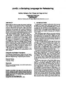
FDPM, for frequency domain photon migration spectroscopy, is a new way of detecting breast cancer noninvasively. The MiniFDPM system [9] performs broadband modulation on the intensity of near-infrared laser diodes and measures the phase and amplitude of backscattered light. Then, a host computer can use the data to derive the scattering and absorption coefficients of the tissue for content based detection of tumors. The Mini-FDPM system consists of a broadband signal generator, laser drivers, a photo detector, and an MCU (Fig. 6). The MC9S12NE64 is a 16-bit MCU with an integrated 10/100 Mbps Fast Ethernet controller. It has an 8K data SRAM and 64K program flash, which are the largest among our hardware platforms. It controls peripheral devices including the frequency synthesizers
Figure 7: The AVR Butterfly platform and the laser drivers through I2 C, SPI, and GPIO pins, and performs measurements with its built-in ADC. The samples are sent back to the host computer over Fast Ethernet. We ported a version of Tapper that consists of a script interpreter and routines for accessing the built-in Ethernet, flash memory, SPI, I2 C, ADC, and GPIO.
5.1.2
AVR Butterfly
Fig. 7 shows the AVR Butterfly [1], an evaluation platform demonstrating the capabilities of the AVR MCU. The board is the most resource-rich and memory-constrained. The Atmel ATmega169V 8-bit MCU runs at up to 8MHz and has a 512B EEPROM, 1KB SRAM, 16KB instruction memory, and peripherals including a data flash, speaker, sensors (temperature, light, voltage), joystick, and an LCD. We also connected a tri-axial accelerometer to its input pins and an nRF2401 radio transceiver to this board, so that it is functionally a superset of the Eco node.
5.2
Application Development by Scripting
We scripted several applications on these platforms. We present case studies to demonstrate the advantages in terms of portability, code size, and dynamic reconfigurability.
5.2.1
3-D Tilt Monitor
The first application for Tapper is a real-time 3-D tilt monitor. The sensor node collects data from a tri-axial accelerometer via the AD converter and transmits the data over the RF link to the base station. A host GUI (Fig. 8) receives the data from the base station, tracks the tilt, and renders a rotated cube in 3D using OpenGL in real-time. Initially the base station is configured to connect to the host computer over RS232 or Ethernet. The host computer can send control commands to the base station and sensor nodes using a terminal program. The following is a sample interactive session with Tapper, where >> is the prompt: # 3D tilt Monitor >>!S # software reset base station
Table 3: Experimental hardware platforms for Tapper Platform MCU Type Prog. Mem (bytes) RAM (bytes) Timers Wired Comm. Type Wireless Comm. Type
Mini-FDPM MC9S12NE64 64K 8K 4 RS-232, Ethernet (built-in) N/A
AVR Butterfly ATmega169V 16K 1K 3 RS-232 nRF2401
Eco nRF24E1(8051 compatible) 4K (32K ext. EEPROM) 256 3 RS-232 nRF2401 (built-in)
16000 14000 12000
Byte
10000 8000 6000 4000 2000 0 Eco Station System Primitives
Eco Node
AVR Butterfly
Command Buffer Manager
Mini-FDPM
Script Interpreter
Other
Figure 9: Tapper flash memory footprint Figure 8: Real-time 3-D tilt monitor 8000 7000
>>RS 101!S
# send software reset command # to node communication with channel 101 >>SET RF.RR(INT=0) # disable RF interrupt >>RS 101 {D500; RA101 50} # tell base station to # send command {D500, RA101 50} to node >>RL # tell base station to listen to incoming data
6000
Byte
5000 4000 3000 2000
The sequence of commands shown above can be turned into a script for the 3-D tilt monitor. On startup, the host computer sends a reset command to reset the base station. Next, it asks the base station to send the same reset command to the sensor node that talks to the station on channel 101, and the third line disables the RF interrupt on the station. The next compound command tells the sensor node to delay for 500ms, start sampling ADC values, and send back data at a rate of 50Hz. Finally, the base station is set to listen mode, and it will keep listening to the radio and send the data back to the host. This case study shows several advantages of scripting. First, the script is only 39 bytes long. Second, it provides interactivity, something that a compiled program cannot do unless programmed in explicitly. Third, it is portable: the same script runs on both Eco (8051) and the AVR Butterfly (ATmega169V) without any modification. These advantages are expected to facilitate and accelerate application development for heterogeneous sensor networks.
5.2.2
Surge
Surge is an application in which a sensor node samples a photo sensor every 2 seconds and sends the data to the host. It was written in ∼20 lines of Java [7]. The same functionality can be written in three lines of a Tapper script: >>+RP{b= RR1; RS 101 b} >>SET RF.RR(INT=1, FUNC=RP) >>T2048{a=A0; b=Pack a; RS 101 b}
Line 1 defines a new subroutine as “RP”, which receives an incoming packet and relays it through channel 101. Line 2 enables the RF receiving interrupt and sets the interrupt handling function to “RP”. Line 3 repeats the sensor reading on ADC channel 0, packaging data by calling the subroutine “Pack”, and sending the packet
1000 0 Eco Station
Eco Node
AVR Butterfly
Mini-FDPM
Figure 10: Tapper data memory foorprint
over RF every 2 seconds. Instead of using an event listener [7], we directly utilize the interrupts supported by the underlying hardware and simplify the coding greatly. A slightly higher level alternative is to replace the reference to ADC channel 0 with a symbolic reference to the photo sensor. Because Rappit tracks the configuration of the sensor nodes, it can substitute the photo sensor name with ADC channel 0 during the host-assisted pre-processing of commands.
5.3
Memory Usage
The Tapper kernel includes the command buffer manager, the interpreter, and the system primitives. Since Tapper is customizable, the code size for each component varies on different platforms, mainly due to the system primitives. Fig. 9 shows the flash memory footprints and the breakdown for each Tapper component for our four different hardware platforms, namely the Eco station, Eco node, AVR Butterfly, and Mini-FDPM. The system primitives are platform dependent, and they range from 1K bytes to nearly 10K bytes on the Mini-FDPM, where it implements a TCP/IP protocol stack that occupies 6K bytes. The sizes of the command buffer manager on different platforms are similar at around 700 bytes, though sizes of the interpreter range from 2K to 4K bytes. Even on the similar platforms, such as the Eco station and Eco node, the difference in the interpreter size is still more
Communication Delay Vs. Command Length
Table 5: Communication latency for links (10-byte payload)
70 60
data rate (Kbps) latency (ms)
Delay(ms)
50
nRF2401 250 16.2
handler, the MCU no longer pays this overhead. Besides, Tapper’s scripting results in small application size, ability to compose these primitives, and instant portability. We believe these benefits significantly outweigh the overhead.
30
10 0 20 50 100 10 Command Length(byte) RS-232@19200bps Ethernet@10Mbps 1
Figure 11: Communication latency vs. command length
Table 4: Interpretation overhead for the Mini-FDPM. Description Read I/O port Write I/O port Read ADC0 Read flash word write flash word
Cmd. Len. 3 5 2 7 10
Interp. overhead (clks) 20 181 147 3171 2696
than 1K bytes. Further investigation reveals that since there is a serial connection to the host computer, we are able to send debugging messages back to the host computer to help the user debug the system. Those debugging messages are useful, though they occupy a large fraction of the memory space. After removing the debugging messages in the interpreter, the code size of the Eco station drops from 5631 to 4887 bytes, where the interpreter takes up 2252 bytes, which is only 100 bytes more than the Eco node. The other difference is due to the different command sets on these systems. Fig. 10 shows the data memory usage for all four platforms. The Eco station and Eco node use up their entire 256 bytes of memory. This is not surprising, because we allocated the maximum available data memory to the command buffer. Mini-FDPM occupies a large data memory of 7.1K bytes. However, 6K bytes of the total are allocated for the Ethernet buffer.
5.4
Ethernet 10,000 0.94
40
20
Command PG0 PG0=1 A0 fr f000 fw f000:11
Serial port 19.2 15.0
Interpretation Overhead
We measure the interpretation overhead by using the timer on the sensor node. First, the timer’s clock is set to the bus clock. Then, we record the timer values before and after calling the interpreter and compare them with direct calls to native functions. Table 4 shows the interpretation overhead in clock cycles for the Mini-FDPM system. The results show that longer commands tend to require more cycles to interpret, although not always. For example, the 2-byte ADC command “A0” takes 147 cycles, while the 3byte GPIO command “PG0” takes 20 cycles. As another example, the 7-byte flash read command “fw” takes 3171 cycles, which is 475 cycles more than the 10-byte flash write command “fw”. This is because the last three bytes of “fw” are a string, the interpreter can simply pass the pointer to the native function. Note that a direct comparison with native calls may not be fair for several reasons. First, our interpretation overhead encompasses interactivity and rapid configurability, which would otherwise require support from much larger runtime systems that consume much more program and data memory, Second, the overhead is paid mainly during interactive execution, but once a routine is configured as a
5.5
Communication overhead
Table 5 lists the data rate and the actual delay of each communication link for transferring a command with 10 bytes of data. Ethernet is the fastest and can issue a command in less than 1ms. One interesting fact is that even though the radio transceiver’s 1Mbps data rate is much faster than the serial port, it actually incurs a longer latency to transmit the same payload size of up to 24 bytes. This is because the RF transceiver’s MAC adds a preamble and CRC to the data packet before transmission. Ethernet has even higher overhead than the RF on preparing the data packet for transmission. It would be more efficient to send a larger data packet instead of several smaller ones with the same total payload size. Fig. 11 compares the communication delays with the command lengths for RS-232 and Ethernet. We can see that as the command length increases, the communication latency of RS-232 increases rapidly, while Ethernet maintains almost a constant latency. Based on these results, one possible way to improve the communication overhead is to send a larger data packet that contains more commands especially for Ethernet communication. We apply this technique to the Mini-FDPM system. The original application scripts for the Mini-FDPM contains 110 commands (534 bytes) and takes 5 seconds to run. On the host computer side, we modify the terminal program to send the commands at 1024 bytes per data packet. The result shows a dramatic reduction in execution time from 5 seconds down to 0.5 second. The drawback however is that it requires a much larger data buffer for the data packet.
6.
DISCUSSION
We learned several lessons from our development experience with porting Tapper to these different hardware platforms and applications. This section discusses issues with hardware primitives, memory usage, and platform dependence.
6.1
System Primitives
As mentioned in Section 4, to save memory, the Tapper kernel may be customized by including only the subset of primitives that are actually needed. The user can customize a Tapper system by configuring it with a subset of standard primitives or adding their own primitives, depending on the potential applications and the role of the system in the network. Based on different primitives included, the interpreter can be optimized to parse only the subset of commands included to reduce code size. Combining several primitives that always go together into a single command can potentially save several thousand cycles per invocation.
6.2
Data vs. Program Memory
Many MCUs have much more program memory than data memory, because program memory stored in EEPROM or flash consume much less power than RAM and can retain their content without power. Subsetting the primitives tends to save much more program memory than data RAM. However, if the user wants to make changes to the hardware or the application, it may be necessary
to rebuild the kernel again. In general, we attempt to maximize the number of hardware primitives under the memory constraints on not only the flash memory but also data memory for the data buffers. For example, the Eco node has a 32K EEPROM for program, 4K SRAM shared between program and data, and 256 bytes data. The EEPROM is plenty for the Tapper kernel, but statically allocating data buffer for these primitives is likely to exceed this limit, even if not all primitives are invoked by any given application. Moreover, the application scripts also require space in the command buffer, both in interactive and batch modes. If there is not enough data memory, then the maximum command length may be severely limited, and a user may have to use short commands entirely in interactive mode, thereby increasing execution time substantially. On the other hand, allocating too much data memory to the command buffer prevents the inclusion of more system primitives. To address the problem of memory allocation, two solutions are being evaluated. The first solution is to perform relative addressing by assigning a different base address for each buffer to be activated. This can reduce data RAM fragmentation and enable more subsets of primitives to be activated. However, indirect addressing will increase the instruction count and therefore runtime overhead. The second solution is to borrow ideas from traditional virtual memory management but adding host assist. The memory of the host computer can serve as the backing store for the sensor node, and the host computer can implement a memory manager to help place or replace the memory block on the sensor node. This can increase the flexibility and reduce the memory usage of the sensor node substantially.
7.
CONCLUSIONS
This paper presents a software architecture based on Tapper, a lightweight scripting engine for highly resource-constrained wireless sensor systems. Tapper’s scripts are not only a higher level way for interactive and batch access to common features on sensor nodes, but they also serve the purpose of a common interoperable message format for heterogeneous sensor networks. We have ported Tapper to different hardware platforms, from simple 8-bit 8051 and ATmega 169V MCUs to 16-bit HCS12 MCUs with Fast Ethernet running a TCP/IP stack. The Tapper approach achieves evolvability and interactive access using substantially less resource than the closest alternatives based on multiple software layers. Our scripting engine occupies less than 5K bytes of space with low interpretation overhead ranging from under 20 cycles to 3000 depending on the syntax complexity of the specific command. However, existing approaches cannot achieve the same advantages of interactivity, portability, small code size, and high level control while still fitting in the same small memories. Overhead due to communication can be amortized over larger volumes of data provided sufficient buffering space is available. Our future work includes enhancing the memory management scheme and developing a Tapper network by extending the Tapper concept to a whole distributed sensor network.
Acknowledgments This work was supported by the National Science Foundation grant CCR-0205712 and an NSF CAREER Award CNS-0448668, and sponsored in part by the National Institute of Health through an NTROI (Network for Translational Research on Optical Imaging) seed grant. The authors thank Chulsung Park and Keun Sik No for the help in performing the experiments on Eco and Mini-FDPM.
8.
REFERENCES
[1] Atmel Corporation. AVR Butterfly evaluation kit: User guide. http://www.atmel.com/dyn/resources/ prod_documents/doc4271.pdf, 2005. [2] Freescale. MC9S12NE64 16bit mircocontroller. http://www.freescale.com/webapp/sps/ site/prod_summary.jsp?code=MC9S12NE% 64&nodeId=0162468636K100, 2004. [3] J. Hahn, Q. Xie, and P. H. Chou. Rappit: A framework for the synthesis of host-assisted light-weight scripting engines for adaptive embedded systems. In Proc. (CODES+ISSS), pages 315–320, September 2005. [4] C. Han, R. Kumar, R. Shea, E. Kohler, and M. Srivastava. SOS: A dynamic operating system for sensor networks. In Proc. of the 3rd International Conf. on Mobile Systems, Applications, And Services (Mobisys), June 2005. [5] J. Hill, R. Szewczyk, A. Woo, S. Hollar, D. Culler, and K. Pister. System architecture directions for networked sensors. SIGOPS Oper. Syst. Rev., 34(5):93–104, 2000. [6] J. Hui and D. Culler. The dynamic behavior of a data dissemination protocol for network programming at scale. In Proc. of the International Conf. on Embedded Networked Sensor Systems (SenSys), pages 81–94, November 2004. [7] J. Koshy and R. Pandey. VM? : Synthesizing scalable runtime environments for sensor networks. In Proc. of the 3rd International Conf. on Embedded Networked Sensor Systems (SenSys), pages 243–254, November 2005. [8] P. Levis and D. Culler. Mat´e: A tiny virtual machine for sensor networks. In Int’l Conference on Architectural Support for Programming Languages and Operating Systems (ASPLOS X), pages 85–95, October 2002. [9] K. S. No and P. H. Chou. Mini-FDPM and heterodyne Mini-FDPM: Handheld non-invasive breast cancer detectors based on frequency-domain photon migration. IEEE Transaction on Circuits and Systems, 52(12):2672–2685, 2005. [10] Nordic Semiconductor. nRF24E1 transceiver / MCU / ADC. http://www.nvlsi.no/index.cfm?obj= product&act=display&pro=79, 2002. [11] J. K. Ousterhout. Scripting: Higher level programming for the 21st century. IEEE Computer, 31(3):23–30, March 1998. [12] C. Park and P. H. Chou. Eco: Ultra-wearable and expandable wireless sensor platform. In to appear, in Proc. Third International Workshop on Body Sensor Networks (BSN 2006), April 3-5 2006. [13] C. Park, P. H. Chou, and Y. Sun. A wearable wireless sensor platform for interactive art performance. In to appear, in Proc. Fourth Annual IEEE International Conference on Pervasive Computing and Communications (PerCom 2006), March 13-17 2006. [14] C. Park, J. Liu, and P. H. Chou. Eco: An ultra-compact low-power wireless sensor node for real-time motion monitoring. In Proc. of the 4th International Conf. on Information Processing in Sensor Networks (IPSN), pages 398–403, April 2005.