Hindawi Publishing Corporation Journal of Robotics Volume 2013, Article ID 483095, 15 pages http://dx.doi.org/10.1155/2013/483095
Research Article Task Allocation and Path Planning for Collaborative Autonomous Underwater Vehicles Operating through an Underwater Acoustic Network Yueyue Deng, Pierre-Philippe J. Beaujean, Edgar An, and Edward Carlson Department of Ocean and Mechanical Engineering, Florida Atlantic University, 777 Glades Road, Boca Raton, FL 33431, USA Correspondence should be addressed to Pierre-Philippe J. Beaujean;
[email protected] Received 19 June 2012; Revised 11 December 2012; Accepted 21 December 2012 Academic Editor: Duˇsko Kati´c Copyright © 2013 Yueyue Deng et al. This is an open access article distributed under the Creative Commons Attribution License, which permits unrestricted use, distribution, and reproduction in any medium, provided the original work is properly cited. Dynamic and unstructured multiple cooperative autonomous underwater vehicle (AUV) missions are highly complex operations, and task allocation and path planning are made significantly more challenging under realistic underwater acoustic communication constraints. This paper presents a solution for the task allocation and path planning for multiple AUVs under marginal acoustic communication conditions: a location-aided task allocation framework (LAAF) algorithm for multitarget task assignment and the grid-based multiobjective optimal programming (GMOOP) mathematical model for finding an optimal vehicle command decision given a set of objectives and constraints. Both the LAAF and GMOOP algorithms are well suited in poor acoustic network condition and dynamic environment. Our research is based on an existing mobile ad hoc network underwater acoustic simulator and blind flooding routing protocol. Simulation results demonstrate that the location-aided auction strategy performs significantly better than the well-accepted auction algorithm developed by Bertsekas in terms of task-allocation time and network bandwidth consumption. We also demonstrate that the GMOOP path-planning technique provides an efficient method for executing multiobjective tasks by cooperative agents with limited communication capabilities. This is in contrast to existing multiobjective action selection methods that are limited to networks where constant, reliable communication is assumed to be available.
1. Introduction Autonomous underwater vehicles (AUVs) represent one of the most challenging frontiers for robotics research. AUVs work in an unstructured environment and face unique perception, communication, and control difficulties. Currently, the state of the art in mission planning is dominated by single AUV operations using preplanned trajectories with offline postprocessing of the data collected during the mission. Multiple cooperative vehicle systems (MCVSs) hold great promise for use in large-scale oceanographic surveys, mine countermeasures (MCMs), and other underwater missions, due to better resource and task allocation [1–3]. Simultaneous use of multiple vehicles can improve performance, reduce mission time, and increase the likelihood of mission success. It is not necessary for all the vehicles in an operation to be the same. In fact, heterogeneity could become a powerful driver of multiple AUV (MAUV) operations.
Instead of using a single vehicle or a homogeneous fleet able to perform every possible mission, a fleet could comprise a variety of AUVs [4]. Different missions would be accomplished using different combinations of vehicles. The key to obtaining the greatest benefit from MAUV or combined operations is cooperation. Cooperative strategies among multiple underwater vehicles can be complex. In addition, communication is a critical aspect of vehicle cooperation and must not be trivialized, as underwater communication is notoriously difficult, slow, and limited in range [5]. The work presented here addresses the two closely coupled problems of multivehicle underwater operations, which are (1) how to assign tasks to each vehicle efficiently and robustly, and (2) how to ensure rapid and effective vehicle actions. The main contributions of this article are the following: (1) first are the design and simulation of a path-planning controller that efficiently handles the cooperative operations
2 of multiple underwater vehicles using underwater acoustic communication; this path-planning controller uses a grid-based multi-objective optimal programming (GMOOP) approach; GMOOP finds the optimal vehicle command decision given a set of objectives and constraints; (2) second are the design and simulation of a location-aided task allocation framework (LAAF) in the form of a task allocation algorithm specially designed for harsh underwater acoustic communication environments. The LAAF and GMOOP controllers are combined in a “task-plan-act” structure [6] to generate an optimized local system output in a timely manner to achieve fleetwide cooperation. This paper is organized as follows. Section 2 briefly reviews the literature on multiple collaborative underwater vehicle research. The next two sections present the LAAF task allocation protocol and the GMOOP multiple-objective control method. Section 5 presents the mission scenarios that employ these methods. Section 6 shows the simulation results. The final section presents a summary of our research and concluding remarks.
2. Literature Review on Collaborative AUVs This section briefly states the research problem of interest and reviews existing research work on underwater acoustic communication, task allocation strategies, path planning, and control for multiple collaborative AUVs. 2.1. Problem Statement. Our mission interest is to search and classify underwater targets. In this mission, two classes of vehicles are involved. Every search vehicle (SV) is equipped with wide field of view target detection sonar. These sensors cover a large volume of water but do not have sufficient resolution to discern the specificity of the targets. In contrast, every classify vehicle (CV) is equipped with a narrow fieldof-view, high-resolution sonar. These sonar systems cover a small volume of water with sufficient resolution for target classification. In this work, the main focus is the task acquisition and execution of the CVs’ mission. The target distribution is assumed to be known a priori to SVs. Similar approach of using heterogeneous robots in a cooperative mission has been demonstrated [4, 7, 8] and viewed as a feasible and cost-effective means to carry out search and classify missions. 2.2. Underwater Acoustic Communication. Cooperative control and optimization for multiple collaborative autonomous underwater vehicles has become a vital area of research [1, 2, 4, 6]. Although some of the prior work are closely related to this research, few address the same problems specifically related to underwater environments with realistic acoustic communication constraints [9–11]. Underwater acoustic networking is an enabling technology for various collaborative missions involving multiple autonomous underwater vehicles [5]. Unfortunately, underwater acoustic communication is slow and limited in range, which impacts MCVS controllers. The proposed research problem is significantly different from those reported using unmanned aerial vehicles (UAVs)
Journal of Robotics as the intervehicle communication can only be achieved via sound propagation [12, 13]. In addition, all UAVs are mostly equipped with high precision navigation sensors onboard (with GPS) whereas the navigation of most underwater vehicles is still based on the traditional dead-reckoning techniques or motion sensors’ fusion. 2.3. Dynamic Task Allocation. In dynamic task allocation, every robot assignment is dynamically adjusted with changes in the environment or group performance. While coordination algorithms for task allocation use only local sensing [14], these algorithms do not take advantage of the underwater acoustic network capability and formal analysis tools are lacking. Task allocation models can be classified as either centralized or distributed. In centralized models, a central agent exists and plays the role of arbitrator. This arbitrator aggregates information from their team members, plans optimally for the entire group, and finally propagates the task assignments to other team members. This model has the advantage of finding the optimal solution, but it generally falls short in harsh underwater communication and partially observable environment as these controllers cannot handle tight MCVS coordination due to limited flexibility and long response time [6, 15]. The distributed task allocation approach handles this shortcoming [16, 17]. In a distributed multirobot system, each robot operates independently under local sensing, with high-level system coordination arising from interactions with other robots as well as the task environment [18]. In this approach, agents rely on a predefined negotiation framework that allows them to decide what activity to do next, what information to communicate, and to whom. A difficulty with this approach is that it requires agents to possess accurate knowledge about their environment and assumes that consistent communication among agents is available throughout the mission. Both conditions are difficult to maintain in heterogeneous underwater MCVS. Task allocation among multiple robots is commonly accomplished by market-based methods, which are tested as one of the most successful solutions [12, 19–21]. In traditional task assignment problems, market-based approaches are widely used due to low computational complexity. The original form of auction algorithm was first proposed by Bertsekas [19, 22]. This algorithm operates whereby unassigned agents bid simultaneously for objects thereby raising their prices. The auction algorithm is widely used in task allocation for cooperating UAVs. In [23], Nygard et al. present a network flow optimization model for allocating UAVs to targets. This problem is formulated as a linear programming problem to obtain decisions for allocating the UAVs. The network model has been further studied by Schumacher et al. [12] and Mitchell. In [24], the authors present a team theoretic approach that allows UAVs to perform decisionmaking independently whenever UAVs cannot exchange information.
Journal of Robotics
3
Typically, the task allocation problem divides a mission into individual subtasks and assigns robots to each subtask. Auctions are powerful tools for allocating resources effectively, especially in situations where optimal allocation is expensive to achieve or where the environment is not completely known. Another well-accepted auction algorithm, effective for general multiagent task allocation, is Challenger [18]. The difficulty with this auction algorithm is that it becomes stagnant when cluster-typed targets exist in the search space and it easily fails in harsh underwater environment. It is further challenged in an underwater acoustic mobile ad hoc network (MANET) due to limited network capacity and high latency [25]. As the size of system grows or the network condition deteriorates, market-based approaches are not applicable as the increased demands in communication bandwidth. This leads to emergent coordination through negotiation or selforganized mechanisms. In such methods, individual robots coordinate their actions based solely on local sensing or local interactions. The advantages and disadvantages of the three task allocation methods are listed in Table 1.
time delays are used and no message routing is considered in this simulation platform. Extensive research work has been done on cooperation and coordination of mobile agents. Traditional methods for cooperative underwater vehicles include swarmed cooperative schemes for homogeneous vehicles and low-level cooperative or merely coordinated techniques for simple task accomplishment [27, 29, 33]. For the coordinated maneuver of multiple vehicles, [27] presents a control maneuverintegrated acoustic navigation system for a formation of three AUVs and one surface craft to gradient searching and following missions. In [30], the authors present a theoretical study of the coordination of the geometrical movements of one flotilla of autonomous underwater vehicles. However, these techniques are insufficient for mission planning when a fleet of vehicles operate in a MANET with a very limited communication bandwidth. To better address the dynamic system with behaviorbased strategies, an interval programming (IvP) method is described in [34, 35] to solve multi-objective optimal problems: a mathematical programming model finds an optimal decision given a set of competing objective functions.
2.4. Path-Planning and Multiple-Objective Optimization. Path planning typically involves defining vehicle waypoints based on the minimization of a positive cost metric (typically a function of mission time or energy consumption), under certain constraints and objectives. In [27], a motion control algorithm is proposed, which constructs adjoint equations based on the vehicle velocity, the time to reach the target, and the optimal usage of the battery life. Cooperative strategies among heterogeneous vehicles are difficult to devise. MCVSs with heterogeneous agents need an advanced formation structure, a dynamic task, and resource allocation algorithm as well as powerful techniques to construct and optimally solve a path-planning problem. Additional complexity arises from the challenges of limited navigation and communication capabilities in the underwater environment. For a network of vehicles to communicate, additional constraints, such as transmission delay and throughput, would need to be considered. In this case, queue length and bandwidth efficiency must be accounted for. With the objective to maximize throughput and queue length, a receding horizon control algorithm is proposed in [28], which yields unique, piecewise continuous optimal controllers that limit and route traffic. There has been significant work reported in MCVS architecture applicable to multiple AUVs as well as MCVS simulation platform [13, 29–32]. However, the research findings and conclusions from these works are based on the assumption of idealized underwater communication conditions. In [32], a simulation environment for the coordinated operation of multiple autonomous underwater vehicles is presented with five clearly defined control architecture layers: the physical layer, the abstraction layer, the functional layer, the coordination layer, and the organization layer. One limitation of this simulator is its model of the acoustic environment: simple
3. Location-Aided Task Allocation Framework Protocol We propose a location-aided task allocation framework (LAAF) that addresses these challenges by extending the radio network auction algorithm developed by Chavez [18] and Bertsekas [19] to the AUV network. LAAF uses three types of strategy: centralized, negotiation, and self-organized [26]. This approach does not guarantee an optimal allocation, but it is especially suited to dynamic environments, where execution time might deviate significantly from estimates and where the ability to adapt to changing conditions is the key to success. In this framework, each robot considers its local plans when bidding and multiple targets can be allocated to a single robot during the negotiation process. The rest of this section provides a description, within the context of a searchclassify AUV mission, of the LAAF auction algorithms. 3.1. Cost Function. The mission of interest is to search and classify targets with a prior-known distribution. Each target is modeled as a step utility function and considered to be classified when it is within the sensor range of a CV. Assume that 𝑡𝑛 is the time at which vehicle 𝑛 reaches its final waypoint. A cost function that penalizes the maximum completion time (to cover all targets) is traditionally assigned to each vehicle. Unfortunately, such cost function may lead to exceedingly long trajectories for most of the vehicles. To avoid this problem, the authors minimize a cost-to-the-fleet (CTF) function assigned to the SVs and CVs working cooperatively to identify the targets:
CTF =
∑
𝜏 ∈ targets
(𝑃𝜏 +
∑ 𝑛 ∈ classify vehicles
𝑐𝑛𝜏 ) .
(1)
4
Journal of Robotics Table 1: Comparison of centralized, negotiation, and self-organized task allocation [26].
Task allocation
Advantages
Centralized
Close to global optimum
Negotiation Self-organized
Only require short-range communication Robust, scalable
Here 𝑐𝑛𝜏 is the positively defined cost incurred by CV 𝑛 to service target 𝜏 and is defined as the time needed by this CV to reach the target (including foreseeable vehicle collision avoidance). 𝑃𝜏 is the positively defined cost of allocating the optimal CV to classify the target 𝜏. 𝑃𝜏 is a function of two variables computed in the auction algorithm (Section 3.2): the Task Allocation Round Time (TART) and Effective Task Allocation Time (ETAT). Both TART and ETAT depend on the network conditions. TART and ETAT are computed by the simulation tool using the simulator clock. TART is calculated from the time a new classify task is announced to the time that the winner acknowledge message reaches the auctioneer. The role of the auctioneer is assigned to SVs as they carry long-range search sensors. Compared to TART, ETAT ends when the self-determination process is complete. If the task allocation keeps failing due to exceedingly unreliable communication, the auctioneer will stop the task allocation process past a predefined timeout. If the task allocation timeout is reached, TART is set to a very large value (equivalent to infinity) [26]. The relationship between 𝑃𝜏 , TART, and ETAT is TART if all bids are successfully received, { { 𝑃𝜏 = { if the auctioneer times out {ETAT { and at least one bid is received. {
(2)
The output action commands generated using the GMOOP model produces the local optimal value of 𝑐𝑛𝜏 . The corresponding messages are designed to use as few data bytes as possible [36]. The message size is labeled Bytes for Task Allocation (BTA). 3.2. Generic Auction Algorithm. The well-accepted auction algorithm developed by Bertsekas [19, 22] is used as a reference in our analysis. We will refer to this algorithm as the generic auction algorithm from now on. This algorithm determines which robot can best complete a given task, based on their proposed bids. The protocol requires a single controller and an auctioneer. For each auction, the auctioneer needs prior knowledge of the number of bidders and the maximum expected round-trip time of a message in the network. This protocol is characterized by the following assumptions. (1) A single vehicle can be an auctioneer, a bidder, or neither.
Disadvantages Limited to small number of robots; not applicable in worst-case network; computation intensity Not scalable, solution not global optimum Very difficult to achieve global optimum
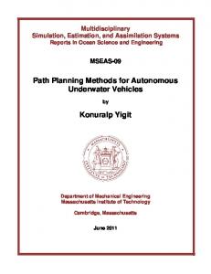
(2) Only one type of tasks can be auctioned among a given set of auctioneers and bidders, and all auctioneers and bidders have a prior knowledge of all task types. (3) All bidders have a cost function which accepts the auction data and returns a bid. The lowest bid wins the auction. (4) Network broadcast is available, so that a single transmission may reach all the nodes in the network. Each bidder replies to each auction announcement with a bid. The bid is an estimate of the time required for the vehicle to accomplish the task, which consists of the time needed to complete all equivalent or higher-priority tasks plus the transit time to the Area of Interest (AOI). Upon winning an auction, a bidder adds the AOI to its task queue. When an AOI task becomes active, the bidder proceeds directly to the AOI. Once in the AOI, if a target is successfully identified, the task is marked as completed. If a search over the entire AOI produces no positively identified targets, the task is marked as incomplete. 3.3. Location-Aided Auction Framework. The reference auction algorithm may fail occasionally due to the unreliable underwater acoustic network. In this paper, the simulated acoustic modem (FAU DPAM) performs poorly beyond 4000 m. In the simulator, the medium model will consistently return a Frame Error Rate (FER, or message error rate) close to 100% beyond 4 km [37]. As shown in Figure 1, even under best-case conditions, the maximum useful range of the modem is not expected to exceed 4096 meters. Therefore, a moving classify vehicle may not be able to return a bid during an auction due to poor communication. Note that the performance curves shown in Figure 1 have been derived by fitting a Nakagami-m model with actual field data [37]. These data were collected under environmental conditions closely resembling those that used the simulation. 3.3.1. Overview. A solution to this problem is to add a self-decision capability to each classify vehicle, based on its knowledge about the overall fleet topology. Each CV accepts or denies the target assignment according to its location relative to the target, any known locations of other vehicles, and any neighbor decision received via the acoustic modem. Once decisions have been made, the same CV will disseminate the results to the entire network. The benefits of self-determination are that a CV can (1) always attempt to classify a target if needed, (2) utilize the
5
1
1
0.8
0.8
FER (prob. of failure)
FER (prob. of failure)
Journal of Robotics
0.6
0.4
0.2
0
0.6
0.4
0.2
0
1000
2000
3000
4000
5000
0
0
1000
2000
(a) Best-case environmental conditions: Nakagami-m = 2.0 and noise PSD = 55.0
3000
4000
5000
Range (m)
Range (m)
(b) Worst-case environmental condition: Nakagami-m = 1.5 and noise PSD = 85.0
Figure 1: Medium model estimation of FER versus range.
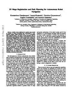
available topology information periodically updated as the mission processes, and (3) reduce the need for underwater communication and, in turn, the response time between detection and classification. None of these features is possible in a generic auction cycle. The shortcoming of this self-determination mechanism is that multiple vehicles may attempt to classify the same target, due to the limited accuracy of the topology information. This can be alleviated by the fact that as the classify vehicles are approaching the same target, the acoustic communication improves. Therefore, the classify vehicles have a more accurate knowledge of the topology and decide whether to abort the target classification. Based on these observations, a location-aided auction framework (LAAF) has been developed. LAAF is an extension of the generic auction algorithm that incorporates a negotiation among all bidders and utilizes the available topology information of the local vehicle. It is designed to meet the challenges of high latency and limited bandwidth of the acoustic network linking the underwater agents. LAAF uses a master-slave architecture which handles most of the allocation work through the acoustic network. If the agents are too far apart to communicate, they identify their individual tasks by reasoning on their available world information. Figure 2 gives an overview of LAAF: when a search vehicle discovers any new target(s), the search vehicle starts an auction for the task(s). It broadcasts an auction announcement message that has a header field to distinguish between single and multiple items. In a scenario of a single-item auction, once the auctioneer has received bids from all bidders, it chooses the best bid and sends out a winner notification message to all the bidders. The auctioneer then waits for the winner-acknowledge message
from the winner and closes the current auction. If the auction times out before the auctioneer receives the winner acknowledge message, the auction will be reinitiated. In the multi-item scenario, a bid message received by the auctioneer contains the optimal configuration for classifying the targets by a set of vehicles, and the auctioneer simply broadcasts the winners to the whole network. In this case, the winner notification is not necessary in LAAF as ETAT is used to evaluate the task assign performance. There are two possibilities that an auctioneer transitions to an auction close state: (1) the auctioneer successfully received a winner acknowledge message, so the target(s) are successfully assigned through auction process; (2) due to poor network conditions, the auction times out and the classify vehicles are left to determine their own tasks based on their knowledge of the fleet topology. 3.3.2. LAAF Bidder Agent’s Policy. Algorithm 1 shows the LAAF algorithm used by a bidder to respond to bid requests from an auctioneer. When a bidder is in the bidding state, it keeps track of the current cost to classifying all the known unclassified targets (base cost), which is added to any further bid calculations. The policy of the bidder in the case of singleitem auction is intuitive; it adds the cost to classify the new task to its base cost and sends it back to the auctioneer. Since the time slot allocated for each node by the Medium Access Control (MAC) is fairly long (typically 5 seconds), LAAF processes multi-items within an auction cycle. In comparison, single-item task allocation generally requires more auction cycles to complete the task allocation. When the bidder agent receives a multiple-item auction request, it selects the target(s) to bid for. An intuitive solution is to
6
Journal of Robotics
Bidder agent
No task
No task
Multi-item
Single item
---
Multi-item
Single item
Negotiation Bidding
Negotiation Bidding
Task assigned
Task assigned Timeout
Timeout Win auction
Win auction
Reasoning Service target(s)
Service target(s)
Task assigned
Reasoning Task assigned
Winner notify
Auction announce
New target(s)
Bidder agent
Enough bids Auction start
Auctioneer agent
Collecting bids
Auction close
Timeout
Figure 2: Location-Aided Auction Framework.
compute all the possible combinational bids and send the bids information back to the auctioneer to select the winner(s). The problem with this method is that for 𝑛 concurrent targets, each bid message contains 𝑃(𝑛, 1) + 𝑃(𝑛, 2) + ⋅ ⋅ ⋅ + 𝑃(𝑛, 𝑛) combinational bids, where 𝑃(𝑛, 𝑖) is the permutation function [36]. This approach requires a large amount of data to be passed between the bidder and the auctioneer in a slow underwater acoustic network. To overcome this problem, each bidder initiates a negotiation process with other bidders. When a bidder receives a multiple-item auction, it calculates a bid for each target in the task announcement and disseminates the bid information through the network. In this case, only 𝑛 bids are disseminated by each classify vehicle. Once a bidder has collected enough negotiation messages from other bidders, it determines the optimal combination of targets’ assignment. By finding the minimum value of all the combinational bids, this bidder finds the optimal list of vehicles to accomplish the multiple-target auction. At the end of this auction, the auctioneer acknowledges the winner. In case of an acknowledgment timeout, the auctioneer reannounces the auction (targets) and starts a new auction process with the same target(s). Simulation results show that when multiple classify tasks are acquired, a CV should reschedule the task list to achieve
optimality [36]. For example, if a CV is on its way to classify a remote target and receives a new task near the current route, this vehicle should adjust the priorities in its task list.
4. Path-Planning and Multiple-Objective Optimization The GMOOP model is designed to find the optimal solutions for a search-classify mission using an action determination map subject to static and dynamic constraints and objectives [36]. Derived from the IvP algorithm [35], the GMOOP model has a similar solution strategy of representing and optimizing over multiple competing objective functions. The main differences are that GMOOP model uses grid maps and addresses the impact of unreliable underwater acoustic communications. In particular, the output of a GMOOP model is the optimized values for command variables. 4.1. Potential Field. The main function of the GMOOP model is to dynamically create paths followed by each vehicle. To do so, it uses a path-planning controller to move the vehicle from one location in the mission field to the next, such that it minimizes a positive cost metric (here the traverse
Journal of Robotics
7
Algorithm Bidder (1) loop (2) Wait-For-Message (3) msg ← Get-Message ∙ Messages of unknown type are silently ignored. (4) timer ← Set-Timer (5) while Not-Expired (timer) (6) if Message-Type (msg) = “auction-announcement” then (7) auction-id, auction-type, auction-data ← Parse-Announcement-message (timer) (8) if Message-Type (msg) = “single” (9) bid ← Create-Bid (auction-id, auction-type, auction-data) (10) Send-Bid (bid) (11) else if Message-Type (msg) = “multiple” (12) Negotiate-Bid (bid) (13) end if (14) else if Message-Type (msg) = “auction-winner” then (15) auctioneer ← Get-Sender (msg) (16) auction-id, auction-data ← Parse-Won-Message (msg) ∙ Note that we acknowledge regardless of whether or not we find the bid. (17) Send-Win-Acknowledgement (auctioneer, auction-id) (18) bid ← Find-Bid (msg) (19) if bid ≠ nil then (20) Add-Task (auction-data) (21) Close-Bid (bid) (22) end if (23) end if (24) Free-Message (msg) (25) end while (26) Start-Self-Determination (27)end loop Algorithm 1: Bidder agent response to auctioneer in LAAF.
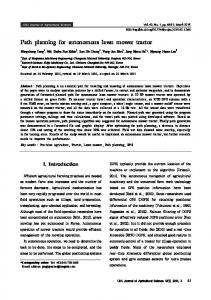
length), while subjecting certain constraints and fulfilling certain objectives. From (1), we know that the general expression of the search-classify mission overall cost to the fleet is CTF, where 𝑃𝜏 is the price paid to find the optimal classify vehicle for target 𝜏. Thus, in the path-planning problem only, the objective is to minimize the cost metric 𝑐𝑛𝜏 , which is the cost incurred by classify vehicle 𝑛 to service target 𝜏. The problem space can be formulated as a set of states denoting vehicle locations connected by directional arcs, each of which has an associated cost. The vehicle starts from an initial state (at the start location) and moves across arcs to other states until it reaches the goal 𝐺𝑡 . A potential field is defined between every combination of neighboring states 𝑋 and 𝑌 to calculate the cost 𝑐(𝑋, 𝑌) of traversing an arc from state 𝑋 to state 𝑌. The optimal neighbor state 𝑌∗ is found by minimizing this cost function. The minimum cost function is the variable 𝑐𝑛𝜏 used in (1). 4.2. Model Elements. The GMOOP algorithm (Figure 3) uses a set of functions that address specific behavior patterns. These functions are defined over an action variable space or
action determination grid map. Grid maps are widely used in vehicle localization and environment estimation [38–41]. The GMOOP algorithm produces an action determination grid map which results from the weighted combination of a series of objective functions. These behavior functions are constrained by the objectives of every vehicle. Collision avoidance from nearby vehicles and fast target engagement are two typical behavior patterns. Each behavior pattern uses a mathematical function of the relative distance between two vehicles or between a vehicle and a target [36]. The action determination grid map contains the value of a specific objective function given a vehicle velocity vector. The variation in time of such a map can be used to predict the trajectory of the vehicle. Each vehicle also carries a vehicle distribution grid map, which contains the location of other vehicles in the search space and areas already covered by a vehicle. Due to uncertainty in the navigation information and acoustic communication, the position information for each vehicle is the combination of a mean value and a probabilistic Rayleigh model. The objective function, defined by the command variables, is applied to the action determination grid map and produces
8
Journal of Robotics
Navigation and target info
Local sensor input
Action info from other vehicles
Acoustic network link
GMOOP model
Mapping from action determination grid map to vehicle distribution grid map
Behavior pattern 𝐵2
Behavior pattern 𝐵1
---
Behavior pattern 𝐵𝐺
Mathematic model 𝑆1
Mathematic model 𝑆2
Mathematic model 𝑆𝐺
Metric func 𝑀1
Metric func 𝑀2
Metric func 𝑀𝐺
Objective func 𝑓1
Objective func 𝑓2
Objective func 𝑓𝐺
Control loop
𝑤1
∑
𝑤2
𝑤𝐺
Overall objective optimal func f
Action determination grid map Piecewise control actions
Figure 3: Components and building processes of the GMOOP model.
a Control Action Output (CAO). The planar form of the overall objective function is given by 𝐺
𝑤𝑔 𝑓𝑔 (𝑢, 𝑣)
𝑔=1
mid
CAO = max { ∑
𝐺
∑ 𝑤𝑔 = 1} .
(3)
𝑔=1
𝑓𝑔 is a behavior function, designed following the potential field approach [42]: neighbor vehicles exert repulsive forces, while the target applies attractive force to the robot. 𝑤𝑔 is the weight for this behavior. (𝑢, 𝑣) represents the north and east component of the vehicle velocity in geographical coordinate.
5. Multiple Autonomous Underwater Vehicle Control Model Used by GMOOP The mission assigned to an underwater vehicle impacts the underwater navigation and underwater communication performance. The simulated missions emphasize rapid target classification using cooperating AUVs which are operating in a congested coastal area. Therefore, collision between vehicles is a real concern. The scenarios considered in this section emphasize the continuous trade-off between collision avoidance, remaining within communication range, and target engagement. 5.1. GMOOP Control Loop. Here we consider the case of a single vehicle controlled by the GMOOP controller. The
required operation involves a vehicle moving through time and space, where periodically, at fixed time intervals, a decision is made as to how to control the next move of the vehicle. As depicted in Figure 4, the next decision occurs at time 𝑡𝑚 , while the output decision 𝑐𝑚 is computed by building and solving the GMOOP problem in the time interval [𝑡𝑚−1 , 𝑡𝑚 ]. The control loop builds and solves the GMOOP model iteratively (Figure 5). Each objective function is defined over a common decision space where each decision precisely spells out the next action for the vehicle to implement starting at time 𝑡𝑚 . 5.2. Vehicles and Environment. The mission of interest is to search and classify underwater targets. Search vehicles act as auctioneers while classify vehicles act as bidders in the task planning process. Both the search and classify vehicles use the GMOOP controller with a group of different predefined 𝑖 (𝑡) (Figure 3) defined as behaviors 𝐵𝑇𝑔 𝑖 𝑖 ⃗ , 𝑝𝐶𝑛⃗ } , 𝑡) , (𝑝𝑑⃗ , {𝑢𝑆𝑚⃗ , 𝑢𝐶𝑛⃗ } , {𝑝𝑆𝑚 𝐵𝑇𝑔 (𝑡) = 𝐵𝑇𝑔
𝑚 ∈ [1, 2, . . . , 𝑀] , M is the total number of SV,
(4)
𝑛 ∈ [1, 2, . . . , 𝑁] , N is the total number of CV. Here 𝑔 ∈ [1, 2, . . . , 𝐺] is the number of behavior types, 𝑖 ∈ [1, 2, . . . , 𝐼] is the vehicle number, and 𝑇 ∈ {𝑆(𝑒𝑎𝑟𝑐ℎ), 𝐶(𝑙𝑎𝑠𝑠𝑖𝑓𝑦)} is the vehicle type. The vehicle position
Journal of Robotics
9
Build and solve the GMOOP model
𝑡𝑚−2 𝑡𝑚−1
𝑐𝑚 𝑡𝑚
Figure 4: The time interval of a decision-making cycle. Sensor input and environmental input
Behavior no.1
Behavior no.2 Objective no.2
Objective no.1
---
Behavior no.𝑛
---
Objective no.3
Control loop
GMOOP problem
Control command
Figure 5: The decision control loop structure.
vector is 𝑝𝑑⃗ , the velocity vector is {𝑢𝑆𝑚⃗ , 𝑢𝐶𝑛⃗ }, and the other ⃗ , 𝑝𝐶𝑛⃗ }. vehicles’ position vector is {𝑝𝑆𝑚 The output is a set of predefined behavior patterns function of the target, vehicle location, and vehicle task information: Fastest to engage target, { { CV {Repulsion from spot by CV, { {Repulsion from spot by SV,
(5)
Follow a predefined trajectory, { { { {Repulsion from spot by CV, SV { { Repulsion from spot by SV, { { {Remain within communication range.
(6)
The vehicle task information includes (a) search or classification information from onboard sensors, (b) destination information assigned by the task auctioneer, (c) other vehicle’s actions and position information obtained through the acoustic network, and (d) the vehicle position.
6. Simulation Results 6.1. Simulator. The simulation tool is the MANET simulator presented in [25, 26, 37], upgraded to support MCVS operations. Several routing protocols can be used in the MANET [25], if necessary. The simulator requires a breadth of inputs, including the number of vehicles, vehicle types, vehicle identification and initial position, target distribution, communication performance, environmental conditions, and priority of various behavior patterns.
The event-driven simulator uses a dedicated process, labeled world, to maintain the clock and environment objects, the true vehicle models, target models, and the sensor (perception) models. Each vehicle object represents an autonomous entity in the environment. The vehicles are created by the user, separate from the simulated environment, and are added to the world before the simulation begins. The world makes the necessary connections between the vehicle systems and the environment. A vehicle requires a helm to maneuver, a protocol stack to communicate, and a sensor to detect objects in the environment. Figure 6 shows a sequence diagram between missionand path-planning controllers and other vehicle modules. It depicts a sequence of messages between multiple modules. The new task has a forward flow from vehicle sensor model to path-planning controller via the mission-planning controller. This new task decision is made by the mission-planning controller based on local vehicle sensor detections as well as by group state from network channels. 6.2. Simulation Using Reliable Acoustic Communications. The target search space is a 1000-by-1000-meter box. The simulation results presented in this paper use one SV and two CVs with a predefined number of targets. The acoustic modem MAC uses time division multiple access (TDMA): every vehicle has a preassigned 5-second transmission slot. Since three vehicles are present in this network, each vehicle transmits information every 15 seconds. We assume that the acoustic modems are operated under mild conditions, that is, at full power with background noise PSD of 55 dB re 1 𝜇Pa/√Hz and some fading (represented by the Nakagami coefficient 𝑚 = 2) [37]. This would correspond to operating
10
Journal of Robotics New task
New task Vehicle sensor model
Mission-planning controller
Path-planning controller
Vehicle helm Vehicle state
Acoustic network protocol stacks Group state
Group state
Vehicle state
Command output
Figure 6: A sequence diagram of mission and path-planning controllers.
the vehicles in shallow waters over sandy bottom in calm seas. We also keep the relative distance between any two vehicles at any given time to be less than 300 m. As a result, messages are almost guaranteed to reach their destination (the simulated FER versus range is shown in Figure 1(a)). The results presented here do not require any data routing, as the vehicles always remain within reliable communication range of one another. The SV is configured to broadcast target announcements to the CVs at specific times, simulating the detection of new targets. Once a CV identifies an unaccomplished target mission in its list, the GMOOP path-planning controller generates an optimal control action every second, with the objective of approaching the target as quickly as possible under the constraint of collision avoidance. 6.2.1. Performance Comparison between Auction Algorithms. Figure 7 shows the specific trajectories of a search-classify mission when the two different auction algorithms are used. The CVs have preassigned classification tasks (T1 and T2 for CV no. 1 and CV no. 2, resp.). At the mission time of 8 seconds, the search vehicle (SV) identifies two new targets T3 and T4 simultaneously. The two-target classify tasks are announced sequentially in the case of a generic auction algorithm and are announced simultaneously in the case of LAAF. In the case of a generic auction algorithm, CV no. 1 wins both classify task bids. Both new tasks are added to CV no. 1’s task list and CV no. 2 stops as it accomplishes the classify task of T2. In the case of the LAAF, the negotiation result is that the concurrent new tasks of T3 and T4 are assigned to both classify vehicles. Thus, CV no. 1 continues to approach to T4 after finishing servicing T1 and CV no. 2 heads for T3 after servicing T2. The differences in using the two auction algorithms are further illustrated in Figure 8. If the generic auction
Table 2: Comparison between generic auction and LAAF, best-case scenario. Auction Method TART (s) Generic auction algorithm 52.7 Location-aided auction 42.7
BTA (bytes) 384 320
ETAT (s) 52.7 12.6
algorithm is used, the two successive auction processes are shown using black and red arrows, respectively. If LAAF is used, only one cycle of task allocation is needed, and the bidders negotiate to select the targets to service (the negotiation processes are highlighted in red in this case). The simulation results are given in Table 2. All three metrics clearly show that LAAF beats the generic auction algorithm and leads to a quicker completion of the mission. 6.2.2. Path-Planning Results. In search and classify missions, there are occasions where the AUVs are so close to one another that collision becomes likely. The scenario considered in this section centers around the need to keep a minimum standoff distance while simultaneously transiting to a destination as quickly and directly as possible. A GMOOP problem is created and solved every second through the control loop. The output of each action determination is a commanded vehicle speed vector, with components in the north and east directions. Figure 9 shows a best-case scenario in which a fourtarget mission is to be completed by two classify vehicles and one search vehicle. The search vehicle (SV) is assumed to remain at the same location throughout the mission and broadcasts the four targets’ location information at certain predefined times. The first and second targets (labeled Tar no. 1 and Tar no. 2) are announced simultaneously by the search vehicle at 𝑡 = 8 seconds. Subsequently, the third
Journal of Robotics
11
Trajectories for search-classify mission (generic auction algorithm) 800
Trajectories for search-classify mission (LAAF) 800
T3
700 𝑥-axis, for north direction (m)
𝑥-axis, for north direction (m)
700 600 500 400 T2 300
T1
200
CV no.2
CV no.1 100 0
T4
T3
T4
50
100
500 400 T2
300
150
200
250
300
350
T1
200
CV no.2
CV no.1 100
SV 0
600
0
400
SV 0
50
𝑦-axis, for east direction (m)
Trajectory of CV no.1 Trajectory of CV no.2 Trajectory of SV no.1 Auction-related messages for T3 Auction-related messages for T4
100 150 200 250 300 𝑦-axis, for east direction (m)
350
400
Trajectory of CV no.1 Trajectory of CV no.2 Trajectory of SV no.1 Auction-related messages for T3 and T4 Auction-related messages for T3 and T4
(a)
(b)
Figure 7: Trajectories for search-classify mission using a generic auction algorithm (a) and LAAF (b).
Trajectories for search-classify mission (LAAF)
320
320
300
300
280
280 𝑥-axis, for north direction (m)
𝑥-axis, for north direction (m)
Trajectories for search-classify mission (generic auction algorithm)
260 240 220
C
200
W
180 160
B2 B1 A
140 120 100
260 240
W
220
C
200
W C R2
180
R1
160 A
N21 N12
A A
140 120
120
140
160
180
200
220
240
𝑦-axis, for east direction (m) A: Single task auction announcement Msg B1 and B2: Bids for a certain auction Msg W: Winner notification Msg C: Winner acknowledge Msg
260
280
100
120
140 160 180 200 220 240 𝑦-axis, for east direction (m)
A: multiple task auction announcement Msg N12 and N21: Negotiation Msg R: Winners results notification Msg W: Winners confirm Msg C: Winners acknowledge Msg
(a)
(b)
Figure 8: Communication messages for task allocation.
260
280
12
Journal of Robotics Table 4: Allocation metrics evaluated for each target, worst-case scenario amongst successful missions.
Trajectories for search-classify mission 𝑥-axis, for north direction (m)
800
Tar no.3
Tar no.4
700
Actual time Target no. announced (s) 1 12.7 2 42.7 3 132.7 4 162.7
600 500 400
Tar no.1
Tar no.2
300 CV no.1
200 SV
100 0
CV no.2
0
50
100 150 200 250 300 𝑦-axis, for east direction (m)
350
TART (s)
ETART (s)
BTA (bytes)
CV no.1 CV no.2 CV no.1 CV no.1
29.7 154.7 29.7 154.7
24.7 149.7 24.7 149.7
160 128 160 128
400
Figure 9: Four targets mission with 2 classify vehicles and 1 search vehicle. Table 3: Task allocation metrics evaluated for each target, best-case scenario. Target no. Actual time Announced (s) 1 12.7 2 42.7 3 132.7 4 162.7
Winner
Winner
TART (s)
ETART (s)
BTA (bytes)
CV no.1 CV no.2 CV no.1 CV no.1
29.7 34.7 29.7 29.7
24.7 29.7 24.7 24.7
160 160 160 160
and fourth targets (labeled Tar no. 3 and Tar no. 4) are announced at 𝑡 = 128 seconds. The mission is complete once each of the four targets has been classified; otherwise the mission times out and is considered a failure. Again, each vehicle has a single 5-second time window to transmit either LAAF task allocation or GMOOP communication messages. The task allocation message has priority over the GMOOP communication message. As shown in Figure 9, all four targets are allocated to the “best” candidates and are classified under the GMOOP controller. The metrics for each classified target are listed in Table 3. Although two targets are scheduled by the search vehicle at the same time in our scenario, they are announced as independent tasks and broadcasted separately to the bidders. In this scenario, there is a time lag of 30 seconds (due to the acoustic modem MAC) between two successive targets announcement. The winning bidder of Tar no. 2 is CV no. 2, indicating that when the two classify vehicles send their bids, CV no. 2 is closer to the bidding target. The total mission time is 214 seconds. The GMOOP-controlled trajectories turn out to be simple in this scenario, because the two classify vehicles keep a relatively large distance from each other. Thus the only objective considered in the GMOOP model is to transit to the target as quickly as possible. 6.3. Simulated Impact of Using Unreliable Acoustic Communications on GMOOP and LAAF. We now assume that the acoustic modems are operated under more severe conditions,
that is at full power with background noise PSD of 85 dB re 1 𝜇Pa/√Hz and severe fading (represented by the Nakagami coefficient 𝑚 = 1.5) [37]. Operating the vehicles over a shallow water reef in rough seas is a good example. We still keep the relative distance between any two vehicles at any given time to be less than 300 m. As a result, messages are much less likely to reach their destination (the simulated FER versus range is shown in Figure 1(b)). Here, we only use LAAF and GMOOP in the simulations. Figure 10 shows scenarios where two classify vehicles are tasked to classify four targets. Eight simulation runs were carried out using the same initial scenario state; four runs are shown. Once again, each bid is sent once (no retry). The initial task allocation messages between SV and CVs are sketched using black lines. We find that the entire mission is completed so long as the four classify tasks reach the CVs. From Figure 10(b), we note that the trajectories of both classify vehicles are the same as shown in Figure 9 (with the best environmental conditions). Figures 10(b) and 10(d) show two successful mission, while Figures 10(a) and 10(c) show two failed missions due to timeout. In Figure 10(a), the search vehicle is able to transmit the Tar no. 1 location information to CV no. 1 at 𝑡 = 12.7 seconds, but this bidding announcement does not reach CV no. 2. Thus the winning bidder for Tar no. 1 is CV no. 1. At 𝑡 = 42.7 seconds, the bidding announcement successfully reaches both bidders, and CV no. 1 wins again in this bidding due to a closer range to Tar no. 2. The bidding announcements for Tar no. 3 and Tar no. 4 do not reach any of the CVs, causing the mission to fail. The performance metrics for each target are listed in Table 4. Compared to Table 2, we note that, for Tar no. 2 and Tar no. 4, there is a great increase in terms of TART and ETART but a decrease in BTA. This is because the winning bidder cannot receive the winner notification message due to the poor network condition. After the predefined timer expires, the classify vehicles switch to the self-determination mode defined in the LAAF auction architecture and finally pick targets on its own.
7. Conclusion In this paper, the authors introduced GMOOP and LAAF. The GMOOP model is intended to balance the competing objectives and constraints for a vehicle in the mission. The LAAF task allocation algorithm is specially designed for the harsh underwater network.
Journal of Robotics
13
800 Tar no.3
700
Tar no.4
600 500 400 Tar no.1
300
CV no.1
200
CV no.2
SV
100 0
Tar no.2
0
50
100 150 200 250 300 𝑦-axis, for east direction (m)
350
𝑥-axis, for north direction (m)
𝑥-axis, for north direction (m)
800
500 400
Tar no.1
300 200
0
100
150
200
800 Tar no.3
Tar no.4
500 Tar no.1
300
CV no.1
200
SV
Tar no.2 CV no.2
100 0
50
100 150 200 250 300 𝑦-axis, for east direction (m)
350
400
(c) Trajectories for search-classify mission
𝑥-axis, for north direction (m)
𝑥-axis, for north direction (m)
50
250
300
350
400
(b) Trajectories for search-classify mission
600
0
CV no.2
SV
100
𝑦-axis, for east direction (m)
800
400
Tar no.2
CV no.1
(a) Trajectories for search-classify mission
700
Tar no.4
600
0
400
Tar no.3
700
Tar no.3
Tar no.4
700 600 500 400
Tar no.1
300
Tar no.2
CV no.1
CV no.2
200 SV
100 0
0
50
100
150
200
250
300
350
400
𝑦-axis, for east direction (m)
(d) Trajectories for search-classify mission
Figure 10: Four executions of the same mission using 4 targets, 2 classify vehicles, and LAAF when acoustic communication is unreliable.
The GMOOP and LAAF algorithms are implemented in the mission- and path-planning module of a simulator. The simulation results show that the location-aided auction strategies performed significantly better than the generic auction algorithm in terms of effective task allocation time and bytes usage. In a simplified task allocation case, the EFAT was reduced by 76.1% and the bytes used for task allocation were reduced by 16.7% due to the self-determination mechanism and multiple-target handling technique. These improvements are essential for communication-based underwater operations in which mission time and bandwidth are critical criteria. In addition, LAAF could still be used with some level of success if underwater acoustic communications become unreliable.
References [1] R. L. Wernli, “AUVs-a technology whose time has come,” in Proceedings of the International Symposium on Underwater Technology, pp. 309–314, April 2002. [2] M. Herman and J. S. Albus, “Overview of the multiple autonomous underwater vehicles (MAUV) project,” in Proceedings of the IEEE International Conference on Robotics and Automation, vol. 1, pp. 618–620, April 1988.
[3] T. R. Cuff and R. W. Wall, “Support platform and communications to manage cooperative AUV operations (OCEANS ’06),” in Proceedings of the Oceans Conference in Asia Pacific, pp. 1–8, May 2007. [4] D. Spenneberg, C. Waldmann, and R. Babb, “Exploration of underwater structures with cooperative heterogeneous robots,” in Proceedings of the Oceans ’05—Europe, pp. 782–786, June 2005. [5] E. M. Sozer, M. Stojanovic, and J. G. Proakis, “Underwater acoustic networks,” IEEE Journal of Oceanic Engineering, vol. 25, no. 1, pp. 72–83, 2000. [6] E. H. Turner and R. M. Turner, “A schema-based approach to cooperative problem solving with autonomous underwater vehicles,” in Proceedings of the Ocean Technologies and Opportunities in the Pacific for the 90’s (Oceans’91), vol. 2, pp. 1067–1073, October 1991. [7] S. M. Smith, K. Ganesan, P. E. An, and S. E. Dunn, “Strategies for simultaneous multiple autonomous underwater vehicle operation and control,” International Journal of Systems Science, vol. 29, no. 10, pp. 1045–1063, 1998. [8] D. Stilwell and B. Bishop, “Platoons of underwater vehicles,” IEEE Control Systems Magazine, vol. 20, no. 6, pp. 45–52, 2000. [9] F. Arrichiello, D. N. Liu, S. Yerramalli et al., “Effects of underwater communication constraints on the control of marine robot
14
[10]
[11]
[12]
[13]
[14]
[15]
[16]
[17]
[18]
[19]
[20]
[21]
[22] [23]
[24]
Journal of Robotics teams,” in Proceedings of the 2nd International Conference on Robot Communication and Coordination, April 2009. M. Vajapeyam, S. Vedantam, U. Mitra, J. C. Preisig, and M. Stojanovic, “Distributed space-time cooperative schemes for underwater acoustic communications,” IEEE Journal of Oceanic Engineering, vol. 33, no. 4, pp. 489–501, 2008. G. Hollinger, S. Yerramalli, S. Singh, U. Mitra, and G. Sukhatme, “Distributed coordination and data fusion for underwater search,” in Proceedings of the IEEE International Conference on Robotics and Automation (ICRA ’11), pp. 349–355, Shanghai, China, May 2011. C. Schumacher, P. Chandler, M. Pachter, and L. S. Pachter, “Constrained optimization for UAV task assignment,” in Proceedings of the AIAA Guidance, Navigation, and Control Conference and Exhibit, pp. 3152–3165, Austin, Tex, USA, 2003. R. M. Turner and E. H. Turner, “Simulating an autonomous oceanographic sampling network: a multi-fidelity approach to simulating systems of systems,” in Proceedings of the Oceans ’00, pp. 905–911, September 2000. H. Bojinov, A. Casal, and T. Hogg, “Emergent structures in modular self-reconfigurable robots,” in Proceedings of the IEEE International Conference on Robotics and Automation, pp. 1734– 1741, San Francisco, Calif, USA, April 2000. B. Jouvencel, V. Creuze, and P. Baccou, “A new method for multiple AUV coordination a reactive approach,” in Proceedings of the 8th International Conference on Emerging Technologies and Factory Automation (ETFA ’01), vol. 1, pp. 51–55, October 2001. B. P. Gerkey and M. J. Matari´c, “A formal analysis and taxonomy of task allocation in multi-robot systems,” International Journal of Robotics Research, vol. 23, no. 9, pp. 939–954, 2004. L. Liu and D. A. Shell, “Multi-level partitioning and distribution of the assignment problem for large-scale multi-robot task allocation,” in Proceedings of the Robotics: Science and Systems Conference (RSS ’11), Los Angeles, Calif, USA, June 2011. A. Chavez, A. Moukas, and P. Maes, “Challenger: a multi-agent system for distributed resource allocation,” in Proceedings of the 1st International Conference on Autonomous Agents, pp. 323–331, Marina del Rey, Calif, USA, February 1997. D. P. Bertsekas, “The auction algorithm: a distributed relaxation method for the assignment problem,” Annals of Operations Research, vol. 14, no. 1, pp. 105–123, 1988. S. Sariel and T. R. Balch, “Efficient bids on task allocation for multi-robot exploration,” in Proceedings of the 19th International Florida Artificial Intelligence Research Society Conference (FLAIRS ’06), pp. 116–121, May 2006. M. J. Matari´c, G. S. Sukhatme, and E. H. Ostergaard, “Multirobot task allocation in uncertain environments,” Autonomous Robots, vol. 14, no. 2-3, pp. 255–263, 2003. D. P. Bertsekas, “An Auction Algorithm for Shortest Paths,” webpage: PSU-auction-28, 1991. K. E. Nygard, P. R. Chandler, and M. Pachter, “Dynamic network flow optimization models for air vehicle resource allocation,” in Proceedings of the American Control Conference, pp. 1853–1858, Arlington, Va, USA, June 2001. J. W. Mitchell, P. Chandler, M. Pachter, and S. J. Rasmussen, “Communication delays in the cooperative control of wide area search munitions via iterative network flow,” in Proceedings of the AIAA Guidance, Navigation, and Control Conference and Exhibit, pp. 2003–5665, Austin, Tex, USA, August 2003.
[25] E. Carlson, P. Beaujean, and E. An, “Location-aware routing protocol for underwater acoustic networks,” in Proceedings of the MTS/IEEE Oceans ’06, Boston, Mass, USA, September 2006. [26] Y. Deng, Task allocation and path planning for acoustic networks of AUVs [Ph.D. thesis], Florida Atlantic University, Boca Raton, Fla, USA, 2010. [27] B. Jouvencel, V. Creuze, and P. Baccou, “A new method for multiple AUV coordination a reactive approach,” in Proceedings of the 8th International Conference on Emerging Technologies and Factory Automation (ETFA ’01), vol. 1, pp. 51–55, October 2001. [28] J. T. Napoli, T. J. Tarn, J. R. Morrow Jr., and E. An, “Optimal communication control for cooperative autonomous underwater vehicle networks,” in Proceedings of the IEEE International Conference on Robotics and Automation, pp. 1624–1631, Barcelona, Spain, April 2005. [29] A. Martins, J. M. Almeida, and E. Silva, “Coordinated maneuver for gradient search using multiple AUVs,” in Proceedings of the Oceans ’03, vol. 1, pp. 347–352, September 2003. [30] R. Kumar and J. A. Stover, “A behavior-based intelligent control architecture with application to coordination of multiple underwater vehicles,” IEEE Transactions on Systems, Man, and Cybernetics A, vol. 30, no. 6, pp. 767–784, 2000. [31] J. Albus and D. Blidberg, “A control system architecture for multiple autonomous undersea vehicles (MAUV),” in Proceedings of the 5th International Symposium on Unmanned Untethered Submersible Technology, vol. 5, pp. 444–466, June 1987. [32] J. B. de Sousa and A. Gollu, “Simulation environment for the coordinated operation of multiple autonomous underwater vehicles,” in Proceedings of the Winter Simulation Conference, pp. 1169–1175, December 1997. [33] Y. C. Sun and C. C. Cheah, “Coordinated control of multiple cooperative underwater vehicle-manipulator systems holding a common load,” in Proceedings of the MTTS/IEEE TECHNOOcean ’04, vol. 3, pp. 1542–1547, November 2004. [34] M. R. Benjamin, “Multi-objective autonomous vehicle navigation in the presence of cooperative and adversarial moving contacts,” in Proceedings of the Oceans ’02 MTS/IEEE, vol. 3, pp. 1878–1885, October 2002. [35] M. R. Benjamin, The interval programming: a multi-objective optimization model for autonomous vehicle control [Ph.D. thesis], Brown University, Providence, RI, USA, 2002. [36] Y. Deng, P. P. J. Beaujean, E. An, and E. A. Carlson, “A path planning control strategy for search-classify task using multiple cooperative underwater vehicles,” in Proceedings of the MTS/IEEE Oceans ’08, Quebec, Canada, September 2008. [37] E. Carlson, P. Beaujean, and E. An, “An Ad Hoc wireless acoustic network simulator applied to multiple underwater vehicle operations in shallow waters using high-frequency acoustic modems,” Journal of Underwater Acoustics, vol. 56, pp. 113–139, 2006. [38] H. Kenn and A. Pfeil, “A sound source localization sensor using probabilistic occupancy grid maps,” in Proceedings of the Mechatronics and Robotics Conference, pp. 802–807, 2004. [39] B. Yamauchi, A. Schultz, and W. Adams, “Mobile robot exploration and map-building with continuous localization,” in Proceedings of the IEEE International Conference on Robotics and Automation, pp. 3715–3720, Leuven, Belgium, May 1998. [40] H. Moravec and A. Elfes, “High resolution maps from wide angle sonar,” in Proceedings of the IEEE International Conference on Robotics and Automation, pp. 116–121, St. Louis, Mo, USA, 1985.
Journal of Robotics [41] A. M. Law and W. D. Kelton, Simulation Modeling & Analysis, McGraw-Hill, 2nd edition, 1991. [42] O. Khatib, “Real-time obstacle avoidance for manipulators and mobile robots,” in Proceedings of the IEEE International Conference on Robotics and Automation, pp. 500–505, St. Louis, Mo, USA, March 1985.
15
International Journal of
Rotating Machinery
Engineering Journal of
Hindawi Publishing Corporation http://www.hindawi.com
Volume 2014
The Scientific World Journal Hindawi Publishing Corporation http://www.hindawi.com
Volume 2014
International Journal of
Distributed Sensor Networks
Journal of
Sensors Hindawi Publishing Corporation http://www.hindawi.com
Volume 2014
Hindawi Publishing Corporation http://www.hindawi.com
Volume 2014
Hindawi Publishing Corporation http://www.hindawi.com
Volume 2014
Journal of
Control Science and Engineering
Advances in
Civil Engineering Hindawi Publishing Corporation http://www.hindawi.com
Hindawi Publishing Corporation http://www.hindawi.com
Volume 2014
Volume 2014
Submit your manuscripts at http://www.hindawi.com Journal of
Journal of
Electrical and Computer Engineering
Robotics Hindawi Publishing Corporation http://www.hindawi.com
Hindawi Publishing Corporation http://www.hindawi.com
Volume 2014
Volume 2014
VLSI Design Advances in OptoElectronics
International Journal of
Navigation and Observation Hindawi Publishing Corporation http://www.hindawi.com
Volume 2014
Hindawi Publishing Corporation http://www.hindawi.com
Hindawi Publishing Corporation http://www.hindawi.com
Chemical Engineering Hindawi Publishing Corporation http://www.hindawi.com
Volume 2014
Volume 2014
Active and Passive Electronic Components
Antennas and Propagation Hindawi Publishing Corporation http://www.hindawi.com
Aerospace Engineering
Hindawi Publishing Corporation http://www.hindawi.com
Volume 2014
Hindawi Publishing Corporation http://www.hindawi.com
Volume 2014
Volume 2014
International Journal of
International Journal of
International Journal of
Modelling & Simulation in Engineering
Volume 2014
Hindawi Publishing Corporation http://www.hindawi.com
Volume 2014
Shock and Vibration Hindawi Publishing Corporation http://www.hindawi.com
Volume 2014
Advances in
Acoustics and Vibration Hindawi Publishing Corporation http://www.hindawi.com
Volume 2014