Task Level Robot Programming Using Prioritized Non-Linear Inequality Constraints Nikhil Somani∗ , Markus Rickert† , Andre Gaschler† , Caixia Cai‡ , Alexander Perzylo† and Alois Knoll‡ Abstract— In this paper, we propose a framework for prioritized constraint-based specification of robot tasks. This framework is integrated with a cognitive robotic system based on semantic models of processes, objects, and workcells. The target is to enable intuitive (re-)programming of robot tasks, in a way that is suitable for non-expert users typically found in SMEs. Using CAD semantics, robot tasks are specified as geometric inter-relational constraints. During execution, these are combined with constraints from the environment and the workcell, and solved in real-time. Our constraint model and solving approach supports a variety of constraint functions that can be non-linear and also include bounds in the form of inequalities, e.g., geometric inter-relations, distance, collision avoidance and posture constraints. It is a hierarchical approach where priority levels can be specified for the constraints, and the nullspace of higher priority constraints is exploited to optimize the lower priority constraints. The presented approach has been applied to several typical industrial robotic use-cases to highlight its advantages compared to other state-of-the-art approaches.
I. I NTRODUCTION Our main motivation in this work is to exploit the paradigm of constraint-based robot programming based on underspecified robot tasks, in order to create a programming interface that is intuitive and natural to use for non-expert users. A majority of current industrial robotic systems lack a clear distinction between task-level programming and robot programming. The ability to program a task by referring to manipulation objects and their properties, without necessarily and explicitly considering domain specific knowledge (e.g., the workspace and robot limits), is important from the viewpoint of intuitiveness. This distinction is a central concept in our approach, where our framework automatically and transparently from the user combines a task description with domain specific knowledge required for execution by a robot. Robotic tasks often do not require strictly defined goals, e.g., for a pick task on a cylindrical pipe-like object, the grasping can be done at any point on its rim. The redundancy can be even higher when these target poses are mapped to robot configurations. We propose the use of geometric interrelational constraints to define such underspecified robot tasks. The possibility of incorporating min/max values or bounds for constraint functions significantly enhances the scope of constraint-based task definitions. As an example, in the grasping scenario presented in Fig. 2, minimum and ∗ TUM CREATE, 1 CREATE WAY, Singapore. †fortiss, An-Institut Technische Universit¨at M¨unchen, Munich, Germany. ‡Technische Universit¨at M¨unchen, Munich, Germany. Correspondence should be addressed to
[email protected]
(a)
𝜃max 𝜃min
(b)
𝜃max 𝜃min
(c)
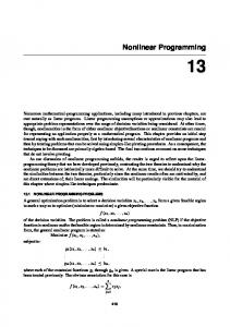
Fig. 1: Manipulation of a tray: The robot task is to carry a tray that contains objects. To prevent the objects from falling, the tray must be kept upright. Allowed tolerances in rotation can be encoded as min-max values of the orientations 𝜃min and 𝜃max along the respective axes. (a) The tray is grasped by a dual-arm robot. A set of min-max constraints can be used to express the inherent flexibility of the grasping task. (b) and (c) The tray is grasped by a single robot arm.
maximum values of the distance from the cylinder’s axis to the tool center point are used to encode the varying span of gripper fingers. Similarly, the cylinder can be grasped higher or lower depending on the length of the gripper fingers. This is expressed as bounds on the vertical distance of the tool center point from the cylinder’s center point. Such constraints are difficult to express without inequalities. Another exemplary robotic task that describes the motivation behind this work is indicated in Fig. 1. The robot
(a)
(b)
(c)
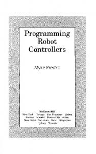
Fig. 2: Underspecified robot tasks: the robot pose is not completely specified and can be moved in the nullspace highlighted by the dotted axes. The grasping point can be located anywhere along the rim of the cylinder (a) (blue). Also, depending on the gripper span (b) and finger length (c), it can be moved along the green and red axes respectively.
holds a tray which carries a cup filled with a liquid. The task for the robot is to carry the tray. The primary constraint related to this task is that the liquid shouldn’t spill. This task can be expressed in the operational space using frameworks such as [1], by fixing the orientation of the tray while keeping the translations free. Additional constraints from the environment (e.g., collision avoidance), robot model (e.g., physical joint limits) and safety requirements (e.g., joint velocity limits) also need to be incorporated. Given the increasing number of tasks and constraints, some of which are also intrinsically non-linear, priorities between them are also essential to represent their relative importances. This can be handled by frameworks such as [2]–[4]. This task can also be expressed using constraints between different frames (robot base, tray, cup) using the iTaSC approach [5]. Depending on the amount of liquid in the cup, the orientation constraints can be relaxed to have minimum and maximum values. This allows more flexibility in task execution and can be handled by frameworks such as [6], [7]. While the aforementioned frameworks can handle this task to varying levels of complexity, they still require the task to be specified in terms of desired poses, velocities, forces or constraints between frames. [8] and [9] go a step further and define tasks as relations between geometric entities that comprise manipulation objects (e.g., orientation of the planar surface of the tray). Our motivation is to develop a framework that can represent such robot tasks using geometric (non-linear) constraints between manipulation objects (with minimum and maximum values), optimally combine them with other constraints (from the environment, robot model, etc.) with different priority levels, and execute it efficiently (< 4ms). The proposed framework is based on a composable structure where several constraints, each describing (parts of) a task or behavior, can be combined. The framework supports several types of constraints: some arise from the task definition (e.g., assembly mating constraints), others from aspects of the robot and the workcell (e.g., obstacles, joint limits). These constraints can be specified at the pose or velocity levels in operational space (𝒙) or the robot’s configuration
space (𝒒). Priority levels can also be specified for each of the constraints. This is useful for enforcing safety constraints, as well as adapting the robot behavior during runtime when not all constraints can be satisfied simultaneously. The solver can exploit the nullspace of mandatory or higher priority constraints to optimize lower priority constraints or secondary objectives (e.g., posture optimization). An important contribution in this work is a constraint-based robot control framework, which takes these different types of (non-linear, inequality) constraints with multiple levels of priorities as input and solves them to obtain target poses for the robot. II. R ELATED W ORK Our work builds upon several classical robotic concepts such as operational space control [1], and ideas such as constraint-based task specification [5], prioritized motion control [4], task-constraint-based control [3], [9], task-space inverse dynamics [10], motion primitives [11], robot skill definitions [12], trajectory optimization [13], geometric constraint solving for CAD models [8] and intuitive interfaces for robot programming [14]–[16]. Constraint-based robot programming has a long history dating back to the task-level planner Handey (1987) [17] and operational space constraints for redundant robots [1], followed by works on multiple objective prioritized control and whole body control in [2], [4], [18], frame-based constraints in iTaSC [5], task-based control [3], and more recently in task space inverse dynamics [10] and geometric constraints based on CAD semantics [9]. In terms of the types of constraints and solvers used, most robotics frameworks optimize in the linear least squares sense, e.g., operational space control [1], iTaSC [5], and more recently in Task-Space Inverse Dynamics [10]. However, most tasks are naturally expressed with inequality constraints, e.g., joint limits [19], collision avoidance [3], [20], and singularity avoidance [21]. A number of frameworks can handle inequality constraints [6], [7], but do not allow prioritized tasks. In [4], a specialized optimal solver that can handle linear inequality constraints with multiple levels of priorities was presented. Many robotic constraints are
TABLE I: Comparison of Control Frameworks Framework
Optimal
Efficient
Geometric Constraints
This work TSID [10] WBCF [2] Lenz et al. [3] iTaSC [5], [7]
3 3 3 3 3
3 3
3
Somani et al. [9] Rodriguez et al. [8]
3 3
3 3
Force Control
Inequality
Hierarchical
Under Actuated
Output
3
3 3 3 3 3
3
𝒒 𝝉 𝝉 𝒒̇
3 3
3 3
3 3 3
non-linear by definition (e.g., manipulability [21]) and the constraint solving framework needs to support this explicitly. Applications based on a representation of coordinate frames and geometric relations between them were presented in [22]. [8] and [9] defined geometric relations between geometric entities (e.g., points, lines, surfaces) that comprise manipulation objects. Modern trajectory optimization frameworks such as CHOMP [23] can keep a given distance to obstacles, and the more recent Trajopt [13] allows operational constraints to be defined. The approach presented in this paper has three new enhancements compared to state-of-the-art approaches (especially to our previous work [9]). Firstly, we create a new and more powerful constraint model and constraint solving formulation that can handle non-linear inequality constraints, thereby allowing us to model much more complicated constraints. Secondly, this framework uses the same constraint formulation to model both task constraints (e.g., geometric inter-relational constraints) and environment constraints (e.g., obstacle avoidance, velocity limits), making it possible to seamlessly integrate them during runtime. Finally, we support different priority levels for tasks, where the low priority tasks are optimized in the nullspace of the higher priority tasks. A qualitative comparison of our framework to other approaches is shown in Table I. As evident from this table, there are several works that have addressed one or more qualitative features that are included in our proposed framework. However, in terms of tasks at the configuration/operational position level, our framework offers a unique and larger set of features than the rest. The support for force constraints is one aspect where some of the other frameworks fare better, and this is a feature that we plan to include in the future. We first describe the modeling of different types of constraints in Section III. Section IV then presents the constraint solving approaches for different applications. Some robotic applications based on our approach are discussed in Section V. Finally, analysis and evaluations of our approach are described in Section VI, followed by conclusion and ideas for future work in Section VII. III. ROBOT CONSTRAINT MODELING Distinction between different types of constraints is an important concept in our approach. Robot independent task constraints depend only on the manipulation objects (e.g.,
3 3
3
3 3
𝒒̇ 𝒒 𝒒
assembly), manipulation constraints (e.g., grasping) depend on the object and tool, workcell constraints (e.g., collision avoidance, velocity limits) depend on the workcell and robot, and robot constraints depend only on the robot model (e.g., joint limits). To execute a task on a robot, several constraints at different levels are combined together, and solved using our constraint solving framework. A. Geometric constraints We use a boundary representation (B-REP) [24] for all geometric entities in the robotic system. This format decomposes each object into semantically meaningful primitive shapes (e.g., points, lines, planes, cylinders). Robot tasks can then be specified in terms of geometric constraints between these entities. Given a fixed and a constrained shape, a geometric constraint adds restrictions to the relative pose of the constrained shape w.r.t. the fixed shape. If both geometric entities can move, an additional constraint is added where the fixed and constrained geometries are swapped. While the definition of constraint functions depends on the involved geometric entities, their bounds also depend on user-specified minimum and maximum values for the constraints. An oriented point in Cartesian space consists of a 3D position (𝒑) and a 3D direction vector (𝒏). Table II lists some of the geometric constraints that are supported by our system and are relevant to our use-cases. B. Environment and safety constraints In addition to direct geometric relations, the robot controller needs to incorporate safety requirements arising from the robot model (e.g., joint limits) and from the workcell/environment (e.g., collision avoidance). Besides these, there are additional limitations on the robot’s speed and acceleration when a human is present in the robot’s workspace to ensure safe collaboration. These constraints are summarized in Table III. 1) Obstacle avoidance: Almost all robot tasks require that collisions are avoided. Minimum distances are efficiently computed between each link of the robot and the object to be avoided using the Gilbert/Johnson/Keerthi algorithm [25]. Each distance computation provides the minimum distance 𝑑𝑖𝑗 , and the points 𝒑𝒊 and 𝒑𝒋 on the robot link 𝐵𝑖 and obstacle 𝑂𝑗 respectively. If the distance 𝑑 is below a threshold value 𝑑thresh , the robot motion is constrained in a way that it does
TABLE II: Summary of supported geometric constraints Fixed Point1
Constrained Point2
Constraint (𝑖)
Constraint Function (gi ) [𝒑21
Distance (𝑑min , 𝑑max )
Plane1
Plane2
Parallel Distance Angle (𝑑min , 𝑑max , 𝜃min , 𝜃max )
Line1
Line2
Parallel Distance (𝑑min , 𝑑max )
Line1
Plane2
Coincident
Point1
Plane2
Distance (𝑑min , 𝑑max )
Point1
Line2
Distance (𝑑min , 𝑑max )
Plane1
Point2
Distance (𝑑min , 𝑑max )
Frame1
Frame2
Transformation
1 ) (𝑻2,𝑑
not move closer to the object, see (1). 0 ≤ 𝑑𝑖𝑗 = ‖(𝒑𝒊 − 𝒑𝒋 )‖ ≤ 𝑑thresh , ∀𝐵𝑖 , 𝑂𝑗
(1)
2) Robot limits: Limitation of the robot kinematic structure, e.g., joint position/velocity/acceleration limits, can be modeled as inequality constraints (Table III). 3) Whole body limits: Limitations on the operational position/velocity/acceleration of each robot link or operational element can also be modeled as inequality constraints (Table III). C. Manipulability optimization The manipulability measure, introduced by Yoshikawa [21], indicates the feasibility of velocities in different Cartesian directions from a given robot pose. It can be used as a quality measure for robot poses, and the optimization goal is to maximize this measure (Table III). (2) shows a unit sphere in joint velocity space, which can be projected into Cartesian space using the pseudo-inverse of the robot Jacobian 𝑱 # (3). This can be simplified to (4), which then represents the space of feasible Cartesian velocities. 𝒒̇ T 𝒒̇ = 1 ) T 𝑱 # 𝒙̇ 𝑱 # 𝒙̇ = 1 ( )−1 𝒙̇ T 𝑱 𝑱 T 𝒙̇ = 1 (
(2) (3) (4)
This can also be understood in terms of the eigenvalues and eigenvectors of 𝑱 𝑱 T , where the eigenvectors represent the axis directions, and square-roots of the eigenvalues the lengths √ ( of )the axes. Yoshikawa’s manipulability measure det 𝑱 𝑱 T specifies the volume of the ellipsoid and is maximized in isotropic configurations (where the lengths of the axes are equal). IV. C ONSTRAINT S OLVING A PPROACH Let the vector (𝒕, 𝒓) denote a pose in operational space with the translation 𝒕 and the rotation represented as axis angles 𝒓 = (𝒘, 𝜃), where ‖𝒘‖ = 1, 0 ≤ 𝜃 ≤ 𝜋. Rigid transformations are represented as 𝒙 = (𝒕, 𝒓). The generic non-linear inequality constraint solving approach in (5) performs optimization in the space of an optimization variable
T𝒑
21 ] [𝒏T1 𝒑21 ; 𝒏2 T 𝒏1 ] [‖𝒑21 − (𝒏𝑇1 𝒑21 )𝒏1 ‖22 ; 𝒏2 T 𝒏1 ] [𝒏2 T (𝒑21 − (𝒏T1 𝒑21 )𝒏1 )] [𝒏2 T 𝒑21 ] [‖𝒑21 − (𝒏2 T 𝒑21 )𝒏2 ‖22 ] [𝒏T1 𝒑21 ] 1 )] [dist(𝑻21 , 𝑻2,𝑑
Lower Bound (lb)
Upper Bound (ub)
2 ] [𝑑min
2 ] [𝑑max
[𝑑min ; cos(𝜃max )]
[𝑑max ; cos(𝜃min )]
2 ; 1] [𝑑min
2 ; 1] [𝑑max
[0]
[0]
𝑑min
𝑑max
2 𝑑min
2 𝑑max
𝑑min
𝑑max
−
−
𝑣. It requires an optimization function 𝑓 (𝑣) along with functions for constraints 𝑔𝑖 (𝑣) and their bounds lb(𝑔𝑖 ), ub(𝑔𝑖 ). Derivatives 𝜕𝑓 ∕𝜕𝒗, 𝜕𝑔𝑖 ∕𝜕𝒗 may also be provided and can be used for the optimization routine. arg min
𝑓 (𝒗)
𝒗
(5)
subject to lb(𝑔𝑖 ) ≤ 𝑔𝑖 (𝒗) ≤ ub(𝑔𝑖 ), 𝑖 = 1, … , 𝑚. This optimization problem (5) is then solved using the non-linear optimization utility from the NLOpt1 library with the COBYLA [26] solver. In case of prioritized tasks, the specialized solver formulation in Section IV-B is used. This is the most generic formulation which is equivalent to the other formulations in some special cases. When the minimization of the joint position distance is at the second priority level and all others are at the first priority level, the prioritized solver is equivalent to the formulation IV-A. A. Optimization in configuration space In this formulation, the optimization is performed over the target configurations of the robot (𝒗 = 𝒒). Since some of the task constraints are functions of relative transformations 𝑔𝑖 (𝒙), there needs to be a function 𝒙 = FK Δ (𝒒) which can be constructed using the forward kinematic function (FK(𝒒)) of the robot (6). FK Δ (𝒒) = FK(𝒒) FK(𝒒current )−1
(6)
The derivative of the cost function (7) can be computed with central differences (8) with a step Δ𝒒 = 1 × 10⁻⁷ 𝜕𝑔𝑖 𝜕𝑔 𝜕𝒙 = 𝑖 𝜕𝒒 𝜕𝒙 𝜕𝒒
(7)
𝜕𝒙 FK Δ (𝒒 + Δ𝒒) − FK Δ (𝒒 − Δ𝒒) = 𝜕𝒒 2Δ𝒒
(8)
The function to be minimized is the distance from the current joint position 𝑞current to the target joint position 𝑞, i.e., 𝑓 (𝒒) = ‖𝒒 − 𝒒current ‖2 in (5). 1 http://ab-initio.mit.edu/nlopt
TABLE III: Summary of supported environment/robot constraints Fixed
Constrained
Constraint (𝑖)
Object 𝑂𝑗
Link 𝐵𝑖
Distance (𝑑min )
− −
Robot Robot
−
Robot
Joint Angles (𝒒min , 𝒒max ) Joint Velocities (𝒒̇ min , 𝒒̇ max ) Cartesian Velocity (𝒙̇ min , 𝒙̇ max )
−
Robot
Manipulability
Input: Optimization variable 𝒗, Constraint functions 𝑔𝑘 , their bounds lb(𝑔𝑘 ) ≤ 𝑔𝑘 (𝒗) ≤ ub(𝑔𝑘 ) (1 ≤ 𝑘 ≤ 𝑚) and priority levels [1, .., 𝑛] Output: 𝒗 for priority level 1 ≤ 𝑖 ≤ 𝑛 do foreach each constraint 𝑔𝑘 do if Priority(𝑔𝑘 ) > 𝑖 then 𝑇lp ← 𝑇lp ∪ 𝑔𝑘 ; if Priority(𝑔𝑘 ) < 𝑖 then 𝑇hp ← 𝑇hp ∪ 𝑔𝑘 ; if Priority(𝑔𝑘 ) = 𝑖 then if 𝑔𝑘 is bounded then 𝑇hp ← 𝑇hp ∪ 𝑔𝑘 else 𝑇lp ← 𝑇lp ∪ 𝑔𝑘 end end end if 𝑇lp = ∅ then 𝑓 = ‖𝒗‖2 else use Equation (9); solve for 𝒗 using Equation (10) foreach each constraint 𝑔𝑘 do if Priority(𝑔𝑘 ) = 𝑖 & 𝑔𝑘 is unbounded then ub(𝑔𝑘 ) ← 𝑔𝑘 end end end Algorithm 1: Constraint solving for prioritized tasks
B. Task priorities and nullspaces In the previous sections, tasks are modeled as constraints 𝑔 in the optimization problem, while the optimization function 𝑓 tries to find the closest robot pose in operational or configuration space that satisfies the constraints. Hence, all task constraints are modeled at the same priority level. While this approach allows finding a solution that satisfies all the constraints simultaneously, it also has some limitations. The optimization function would simply not converge in case some constraints are not satisfiable. In such cases, it is important to define a priority on the constraints so that the optimization of some unsatisfiable constraints can be sacrificed in favor of higher priority constraints. To achieve this, the constraint solving framework is modified. In the new formulation (10), the high-priority tasks (𝑇hp ) are modeled as constraints 𝑔 while the low-priority task (𝑇lp ) are considered as costs that need not be fully satisfied, but minimized. Hence, their distance from their bounds are added to the optimization function 𝑓 (9). Unbounded
Constraint Function (gi ) [ ] ‖(𝒑𝒊 − 𝒑𝒋 )‖
Lower Bound (lb)
Upper Bound (ub)
𝑑min
−
[𝒒] ̇ [𝒒] ̇ [𝒙] √ ( )) ( 1∕ 1 + det 𝑱 𝑱 T
𝒒min 𝒒̇ min 𝒙̇ min
𝒒max 𝒒̇ max 𝒙̇ max
−
−
Axis𝐴 Plane𝐴
Axis𝐵
Cylinder𝐴
Point𝐵1 Point𝐵2
(a)
Plane𝐵
(b) Grasping (All Priority 1)
ParallelDistance(Axis𝐴 , Axis𝐵 ) = [f inger length(𝐵)∕2 − radius(Cylinder𝐴 ), f inger length(𝐵)∕2] Distance(Plane𝐴 , Plane𝐵 ) = [± height(Cylinder𝐴 )∕2] Distance(Axis𝐴 , Point𝐵1 ) = [radius(Cylinder𝐴 ), f inger span(𝐵)∕2] Distance(Axis𝐴 , Point𝐵2 ) = [radius(Cylinder𝐴 ), f inger span(𝐵)∕2] Environment/Robot Constraints Avoid collisions (Priority 1) Minimize Cartesian delta of end-effector (Priority 2)
Fig. 3: Constraints for grasping a cup and avoiding obstacles
(minimization) constraints in 𝑇hp are converted to bounded constraints by setting their bounds to be their function value 𝑔 achieved in the previous iteration. This ensures that the optimal values achieved by these high-priority minimization constraints are not sacrificed by lower-priority constraints. By iterating through several priority levels 𝑗, setting 𝑇hp as the set of all constraints with priority 𝑖 ≤ 𝑗 and 𝑇lp as the set of all constraints with priority 𝑘 > 𝑗, this approach is extended to support multiple priority levels (see Algorithm 1). ⎧ 0 ⎪ 𝑓𝑖 = ⎨ ‖𝑔𝑖 − ub(𝑔𝑖 )‖22 ⎪ ‖lb(𝑔𝑖 ) − 𝑔𝑖 ‖2 2 ⎩
∶ lb(𝑔𝑖 ) ≤ 𝑔𝑖 ≤ ub(𝑔𝑖 ) ∶ 𝑔𝑖 > ub(𝑔𝑖 ) ∶ 𝑔𝑖 < lb(𝑔𝑖 )
(9)
The resulting optimization problem is then ∑ arg min 𝑓𝑖 𝒗
𝑔𝑖 ∈𝑇lp
subject to lb(𝑔𝑘 ) ≤ 𝑔𝑘 (𝒗) ≤ ub(𝑔𝑘 ), 𝑔𝑘 ∈ 𝑇hp .
(10)
B. Cup grasping with obstacle avoidance
Fig. 4: Intuitive user-interface for definition of geometric constraints between individual shape elements of CAD models. After selecting a pair of valid surfaces, the user is presented with a preview of all valid constraints between the selected surfaces.
V. A PPLICATIONS We use our robot programming approach to perform some industrial robotic tasks such as grasping of cylindrical objects and manipulation of a tray. While the constraint models and solver formulations are novel contributions of this work, inverse kinematics, trajectory generation and low-level robot control use the Robotics Library2 by Rickert [27]. A video of the implementation of these applications on a robotic workcell with a Comau Racer7-1.4 robot is attached with the submission, and also available online3 . A. Task-level teaching interface for industrial robots The geometric constraint solver described in this paper is used in the cognitive back-end of a high-level teaching framework for industrial robots [15]. The aim of the framework is to enable shop floor workers, who are experts in their manufacturing domain, to instruct robots without the requirement of being robotics experts. The framework provides domain-specific interfaces [16], which act as a front-end to semantic process descriptions. This semantic description language is based on a logical formalism that allows the system to automatically reason about the state of a process and potentially missing pieces of information. The cognitive capabilities of the system support the human operator and make teaching robot tasks less complex and more efficient. In the domain of industrial assembly, constraints between geometric entities (e.g., workpieces, tools, robot) can be defined by selecting primitive shapes (i.e., surface, edge, point) from their respective CAD models and choosing the desired constraint from a filtered list of possible constraints between the selected entities (Fig. 4). The design of this interface is similar to popular CAD modeling softwares that have been optimized for such mating operations. Hence, the geometric constraints for robotic tasks need not be programmed manually, but can be defined using a 3D GUI. 2 http://www.roboticslibrary.org/ 3 http://youtu.be/baet9IkTK04
This task involves grasping a cylindrical object (a cup), formulated using the constraints shown in Fig. 3. During execution, additional constraints from the environment such as collision avoidance are added. To ensure smooth motion, the Cartesian distance between the end-effectors in successive motions is minimized as a low priority task. This task is demonstrated on two robots: a 6-DOF Comau Racer7-1.4 (Fig. 5a), and a 7-DOF KUKA Light Weight Robot (LWR) (Fig. 5b). The robot utilizes the nullspace of the task to avoid obstacles. In addition to the rotation along the cylinder’s axis, the min-max constraint formulation provides the robot additional degrees of freedom along the length of the cylinder and along the length of the gripper fingers. C. Tray grasping with obstacle avoidance This application involves manipulating a tray containing a can with a liquid (as explained in Section I). It performed using two different robotic platforms. With a 6-DOF Comau Racer7-1.4, the tray was grasped using the parallel gripper on one side (see Fig. 1b). Using a Comau dual arm, the tray was grasped on two sides (see Fig. 1a). The constraint formulations and the task nullspaces are speficied in Fig. 1. The robot can utilize this nullspace to achieve secondary objectives such as avoiding obstacles (see Fig. 5c). D. Pick and place with manipulability optimization This application consists of two tasks: grasping of a cylindrical object at its rim, and placement of the grasped object on another position on the table. Some exemplary grasping poses and the nullspace for the task constraints are illustrated in Fig. 2. The task constraints for the placement step state that the object should be placed in an upright orientation on the table. This is combined with lower-priority posture optimization (manipulability maximization) and solved using the approach in Section IV-B. The grasping pose in the first step of this application is underspecified and can be further refined by jogging the robot in the nullspace of the task constraints (Fig. 2). In Fig. 5d, the first step of this application is shown with transparent objects. Two different locations of the cylindrical object on the table are used to illustrate how the underspecified grasping pose is further optimized in its nullspace to minimize the joint distance from the same starting pose (Section IV-A). The manipulability values of different robot poses on the table are overlaid (red indicates low, and green high) in Fig. 5d. In the second step, the object is moved to a position on the table that maximizes its manipulability. VI. E VALUATION Using the target applications and scenarios described in Section V, some qualitative and quantitative evaluations were done to assess the merits of our approach. All evaluations were performed on a PC with a 4.0 GHz Intel Core i7-6700K CPU and 16 GB of RAM.
(a)
(b)
(c)
(d)
Fig. 5: Execution of constraint-based tasks. (a) Cup grasping with obstacle avoidance using 6-DOF Comau Racer7-1.4, (b) Cup grasping with obstacle avoidance using 7-DOF LWR, (c) Grasping a tray with dual arm and avoiding multiple obstacles, (d) Pick cylinder at rim and place with manipulability optimization.
Our implementation is based on the NLOpt library, where we set the tolerance of the minimization function to be 10−8 and the acceptable tolerances for the inequality constraints as 10−6 . The derivative tolerance is set as 10−8 . A. Runtime evaluation for different tasks In order to assess the time efficiency of our approach, we evaluated the controller runtimes for each of the tasks and target applications mentioned in this paper. The results are summarized in Table IV. The evaluation covers a wide variety of tasks having 2–26 task space constraint dimensions and 1–3 priority levels. For the first 4 tasks in Table IV, the evaluation was performed by solving the constraints from a random initial pose for the robot. The fifth task in Table IV involves manipulability optimization. In this case, random poses within the reachable range of the robot and on the tabletop were chosen for the object to be picked. The last 3 tasks in Table IV include collision avoidance. In these cases, the colliding object was moved along a pre-defined trajectory. A random trajectory was not chosen for the colliding object since it could lead to situations where collision avoidance is impossible. The trajectory was chosen in a way that the robot was able to avoid the collision while satisfying the geometric constraints imposed by the underlying task. In each of these evaluations, the runtime was averaged over 10000 iterations. The average runtime ranges from 0.6 ms for the simplest task to 15 ms for the most complicated one. B. Comparison with other approaches Table I presented a qualitative comparison of the features offered by several state-of-the-art control frameworks. Based on the implementations from our previous works [9], [28], we compare TSID [10], WBCF [2] and our approach in terms of average controller runtime and task errors. We could not use the same set of tasks described in Table IV for this evaluation since the compared frameworks TSID [10], WBCF [2] and even our previous works [9], [28] don’t support inequality constraints. Besides, the aim of this comparison is primarily to prove that the presented approach is at par with state-of-art approaches in terms of computation time
TABLE IV: Runtime evaluation on application scenarios Constraint Dimensions
No. of Priority Levels
Runtime COBYLA (in ms)
Plane Distance Cylinder Grasp Cup Grasp Tray Grasping (Dual) Pick-Place + Manipulability
2 5 6 12 7
1 1 1 2 3
0.6 ± 0.1 0.8 ± 0.1 1.2 ± 0.2 3.0 ± 0.2 2.5 ± 0.3
Cup + Collision Cup + Collision (LWR) Tray Hold + Collisions (Dual)
12 13 26
2 2 2
2.3 ± 0.3 3.3 ± 0.3 15.0 ± 3.0
Scenario
TABLE V: Runtime evaluation of control frameworks Runtime 1 constraint (in ms)
Runtime 2 constraints (in ms)
This work TSID [10]
0.8 ± 0.1 0.5 ± 0.1
0.9 ± 0.1 0.5 ± 0.1
WBCF [2] Somani et al. [9]
0.8 ± 0.1 4.0 ± 1.0
0.8 ± 0.1 5.0 ± 0.8
Framework
and is better suited for real-time control. The first test case involves a plane-plane-coincident constraint (Table II) where 3 DOFs of the robot are fixed. The second test case has two plane-plane-coincident constraints, making 5 DOFs fixed. The tolerance for task errors is set to be 10−6 . The results are summarized in Table V. VII. C ONCLUSIONS AND FUTURE WORK This work presents an approach for constraint-based robot programming, where robot tasks can be formulated using geometric inter-relational constraints. When executed on a robotic workcell, additional constraints arising from the workcell description and the environment can be added dynamically. This collection of prioritized constraints are then solved in real-time to calculate target configurations
for the robot. Preliminary evaluations of this approach, both qualitatively and quantitatively in terms of the task errors and computational time have also been presented. Runtime comparisons of our approach with some state-of-art approaches on some common tasks have also been presented. In conclusion, we have tried to demonstrate the effectiveness of constraint-based methods in robotic applications. The addition of inequality constraints increases significantly the expressive power of constraint-based methods. Our framework, when used in conjunction with intuitive task definition interfaces [15], provides the complete robot programming solution from semantic descriptions to real-time control. This paper has focused on position control and kinematic constraints, and extensions for incorporating robot dynamics and force control in the framework are part of our plans for future work. Also, we have only considered simple primitive shapes (e.g., points, lines, planes and cylinders) for geometric constraints. The use of other generic shape descriptions such as Splines, B´ezier curves or superquadrics to define geometric constraints is an open research topic and is a possible direction for future work. VIII. ACKNOWLEDGMENTS We would like to thank Comau Robotics for providing the hardware and Ahmed Rehman Ghazi (from fortiss GmbH, Munich, Germany) for providing the real-time drivers for the Comau Racer7-1.4 and Comau Smart5 Six 6-1.4 robots that have been used in our experiments. R EFERENCES [1] O. Khatib, “A unified approach for motion and force control of robot manipulators: The operational space formulation,” IEEE Journal of Robotics and Automation, vol. 3, no. 1, pp. 43–53, Feb. 1987. [2] O. Khatib, L. Sentis, J. Park, and J. Warren, “Whole-body dynamic behavior and control of human-like robots,” International Journal of Humanoid Robotics, vol. 1, no. 1, pp. 29–43, 2004. [3] C. Lenz, M. Rickert, G. Panin, and A. Knoll, “Constraint taskbased control in industrial settings,” in Proceedings of the IEEE/RSJ International Conference on Intelligent Robots and Systems, St. Louis, MO, USA, 2009, pp. 3058–3063. [4] A. Escande, N. Mansard, and P. Wieber, “Hierarchical quadratic programming: Fast online humanoid-robot motion generation,” The International Journal of Robotics Research, vol. 33, no. 7, pp. 1006– 1028, June 2014. [5] J. De Schutter, T. De Laet, J. Rutgeerts, W. Decr´e, R. Smits, E. Aertbeli¨en, K. Claes, and H. Bruyninckx, “Constraint-based task specification and estimation for sensor-based robot systems in the presence of geometric uncertainty,” The International Journal of Robotics Research, vol. 26, no. 5, pp. 433–455, 2007. [6] Y. W. Sung, D. K. Cho, and M. J. Chung, “A constrained optimization approach to resolving manipulator redundancy,” Journal of Robotic Systems, vol. 13, no. 5, pp. 275–288, 1996. [7] W. Decre, R. Smits, H. Bruyninckx, and J. De Schutter, “Extending iTaSC to support inequality constraints and non-instantaneous task specification,” in Proceedings of the IEEE International Conference on Robotics and Automation, May 2009, pp. 964–971. [8] A. Rodriguez, L. Basaez, and E. Celaya, “A relational positioning methodology for robot task specification and execution,” IEEE Transactions on Robotics, vol. 24, no. 3, pp. 600–611, June 2008. [9] N. Somani, A. Gaschler, M. Rickert, A. Perzylo, and A. Knoll, “Constraint-based task programming with CAD semantics: From intuitive specification to real-time control,” in Proceedings of the IEEE/RSJ International Conference on Intelligent Robots and Systems, Hamburg, Germany, Sept. 2015.
[10] A. D. Prete, F. Nori, G. Metta, and L. Natale, “Prioritized motionforce control of constrained fully-actuated robots: “Task space inverse dynamics”,” Robotics and Autonomous Systems, vol. 63, pp. 150–157, Jan. 2015. [11] T. Kr¨oger, B. Finkemeyer, and F. M. Wahl, “Manipulation primitives a universal interface between sensor-based motion control and robot programming,” in Robotic Systems for Handling and Assembly, ser. Springer Tracts in Advanced Robotics, D. Schtz and F. Wahl, Eds. Springer, 2011, vol. 67, pp. 293–313. [12] R. H. Andersen, T. Solund, and J. Hallam, “Definition and initial casebased evaluation of hardware-independent robot skills for industrial robotic co-workers,” in Proceedings of the International Symposium on Robotics, June 2014, pp. 1–7. [13] J. Schulman, A. Lee, I. Awwal, H. Bradlow, and P. Abbeel, “Finding locally optimal, collision-free trajectories with sequential convex optimization,” in Proceedings of Robotics: Science and Systems, 2013. [14] N. Somani, E. Dean-Leon, C. Cai, and A. Knoll, “Scene Perception and Recognition in industrial environments,” in 9th International Symposium on Visual Computing (ISVC). Springer, July 2013. [15] A. Perzylo, N. Somani, S. Profanter, I. Kessler, M. Rickert, and A. Knoll, “Intuitive instruction of industrial robots: Semantic process descriptions for small lot production,” in IEEE/RSJ International Conference on Intelligent Robots and Systems (IROS), Daejeon, Republic of Korea, October 2016, https://youtu.be/bbInEMEF5zU. [16] S. Profanter, A. Perzylo, N. Somani, M. Rickert, and A. Knoll, “Analysis and semantic modeling of modality preferences in industrial human-robot interaction,” in Proceedings of the IEEE/RSJ International Conference on Intelligent Robots and Systems, 2015. [17] T. Lozano-Perez, J. L. Jones, E. Mazer, P. O’Donnell, E. W. Grimson, P. Tournassoud, A. Lanusse, et al., “Handey: A robot system that recognizes, plans, and manipulates,” in Proceedings of the IEEE International Conference on Robotics and Automation, vol. 4, 1987, pp. 843–849. [18] S. Chiaverini, G. Oriolo, and I. Walker, “Kinematically redundant manipulators,” in Springer Handbook of Robotics, B. Siciliano and O. Khatib, Eds. Springer Berlin Heidelberg, 2008, pp. 245–268. [19] F. Chaumette and E. Marchand, “A redundancy-based iterative approach for avoiding joint limits: Application to visual servoing,” IEEE Transactions on Robotics and Automation, vol. 17, no. 5, pp. 719–730, Oct. 2001. [20] O. Stasse, A. Escande, N. Mansard, S. Miossec, P. Evrard, and A. Kheddar, “Real-time (self)-collision avoidance task on a hrp-2 humanoid robot,” in Proceedings of the IEEE International Conference on Robotics and Automation, May 2008, pp. 3200–3205. [21] T. Yoshikawa, “Manipulability of robotic mechanisms,” The International Journal of Robotics Research, vol. 4, no. 2, pp. 3–9, 1985. [22] T. De Laet, S. Bellens, R. Smits, E. Aertbelien, H. Bruyninckx, and J. De Schutter, “Geometric relations between rigid bodies (Part 1): Semantics for standardization,” IEEE Robotics Automation Magazine, vol. 20, no. 1, pp. 84–93, Mar. 2013. [23] N. Ratliff, M. Zucker, J. A. Bagnell, and S. Srinivasa, “CHOMP: Gradient optimization techniques for efficient motion planning,” in Proceedings of the IEEE International Conference on Robotics and Automation, 2009, pp. 489–494. [24] A. Perzylo, N. Somani, M. Rickert, and A. Knoll, “An ontology for CAD data and geometric constraints as a link between product models and semantic robot task descriptions,” in Proceedings of the IEEE/RSJ International Conference on Intelligent Robots and Systems, 2015. [25] E. G. Gilbert, D. W. Johnson, and S. S. Keerthi, “A fast procedure for computing the distance between complex objects in three-dimensional space,” IEEE Journal of Robotics and Automation, vol. 4, no. 2, pp. 193–203, 1988. [26] M. J. D. Powell, A Direct Search Optimization Method That Models the Objective and Constraint Functions by Linear Interpolation. Dordrecht: Springer Netherlands, 1994, pp. 51–67. [Online]. Available: http://dx.doi.org/10.1007/978-94-015-8330-5 4 [27] M. Rickert, “Efficient motion planning for intuitive task execution in modular manipulation systems,” Dissertation, Technische Universit¨at M¨unchen, 2011. [28] C. Cai, N. Somani, M. Rickert, and A. Knoll, “Prioritized motionforce control of multi-constraints for industrial manipulators,” in Proceedings of the IEEE International Conference on Robotics and Biomimetics, Zhuhai, China, December 2015.