clearly beyond communication via email, chat-rooms, or whiteboards. ..... and their attributes such as le locator (href), host, and protocol. Third, for ..... thesis.html.
12-th IASTED Intl.
Conf.
on Parallel and Distributed Computing, Collaborative Technologies Symp., Nov.
6-9, 2000
Task ow-Oriented Programming: A Paradigm for Distributed Collaborative Computing Franc Brglez Hemang Lavana Collaborative Benchmarking Laboratory, Department of Computer Science NC State University, Raleigh, NC 27695 http://www.cbl.ncsu.edu/OpenProjects
Abstract { Task ow-oriented programming merges concepts from structured programming, hardware description, and mark-up languages. A mark-up language such as XML supports a well-de ned schema that can capture the decomposition of a program into a hierarchy of tasks. A hardware description language such as VHDL relies on well-de ned and explicit input/output port de nitions to create, at any level of hierarchy, explicit data dependencies among tasks. A structured programming language provides control to sequence the execution of all tasks. We apply these concepts to the design of a distributed user-con gurable environment that supports project-speci c collaborative, networked, and task oworiented programming as well as computing. Starting with the topdown decomposition of a computing project into task, we capture not only the hierarchy of tasks but also explicit and user-de ned dependencies, i.e. directed task=>task control edges. Data dependencies are created implicitly only during the detailed bottom-up implementation of input/output assignments for each task. Task- ow programming is not about programming the tasks. Rather, it is about programming dependency edges between the tasks, task=>task control edges in particular. An executable program is written simply as a (hierarchical) task ow in XML, interconnecting tasks and data. Most task=>task edges are in the 'enabled' state by default and require no programming, while conditions to `enable/disable' the state of task=>task edges are short and simple and are an integral part of the task node encapsulation. Similarly, the data->task and task->data edges are always `enabled'. Keywords: task ow-oriented programming, collaborative computing, Internet. I. Introduction
The notion of collaborative computing has been applied in several contexts. In our work, we consider a collaborative computing project as an entity that engages a project leader and a team of distributed participants in creating an environment to work on the project phases such as � project decomposition into tasks and assigning tasks to project participants; � nding or creating software programs and procedures to complete each task; � assigning programs and libraries of procedures to host computers; � deciding the sequence in which tasks are to be executed; � choosing most appropriate data structures and protocols to protect, share, move, and archive data required by and generated by task-executing programs and procedures;
* F. Brglez and H. Lavana have in part been supported by the contract from DARPA/ARO (DAAG55-97-1-0345).
creating a client GUI that features shared views of the project, including browsing, data editing, and execution of a task or a task sequence; � interfacing clients to a server on a dedicated host to support all phases of the project, including asynchronous mode of collaboration where each participant works on the assigned tasks independently, and a synchronizing collaboration mode where tasks executions are being synchronized with other participants. Groupware environments, supporting e-mail, chat rooms, video conferencing, shared white boards, are frequently equated with `collaborative computing'. However, we view them as facilitators of communication between collaborating participants, rather than a collaborative computing project per se. A collaborative computing project, as de ned in this paper, typically engages a team of distributed participants to create domainspeci c environments, each of which would progress through the project phases listed above. For example: � OpenDesigns projects [1] address VLSI design ows in IC design; � OpenExperiments projects [2] demonstrate an experimental design environment to evaluate heuristic algorithms solving NP-hard problems; � OpenWriter project [3] demonstrates an environment and utilities to support collaborative writing and compilation of a report or a book. The most distinguishing feature of each project environment is the capability not only to encapsulate a number of tasks, represented by distributed stand-alone programs, but also to con gure the seamless execution of the task sequences over the network. Here, project participant's immersion in collaborative computing tasks is clearly beyond communication via email, chat-rooms, or whiteboards. Each of these projects relies on the collaborative client/server architecture (OmniDesk) and the features of the user-con gurable client GUI (OmniFlowLite), described in [4] and [5]. There are relatively few publications in the area of `task-oriented programming'. The same web engine that returns 153,000 hits on the query of "object-oriented programming" returns only 46 hits upon the query of "task-oriented programming", e.g. [6]. Most publications on task-oriented programming appear linked to groups involved in robotics, also pointing to research in `programming-by-demonstration', `session-oriented programming',and `event-oriented programming', e.g. [7, 8]. �
The notion of task ow-oriented programming as de ned in this paper is clearly motivated and structured by factors that are di�erent. In fact, our approach is rooted in the experiences with REUBEN and OmniDesk/OmniFlowLite [4, 5, 9] and we argue that the task ow-oriented programming concepts as introduced in this paper are well-suited to support collaborative and distributed user-con gurable project environments. The paper is organized into several sections as follows: (1) Task ow-oriented Programming Concepts; (2) Graphical User Interface; (3) Collaborative, Networked, Task ow-Oriented (CNT) Structures (4) Scheduling and Execution; (5) Summary and Conclusions. II. Taskflow-Oriented Programming: Concepts
Task ow-oriented programming merges concepts from structured programming, hardware description, and mark-up languages. This section introduces simple definitions and a representative example of the rst two concepts. We discuss the extensible mark-up language (XML) in the sections that follows. Background and De nitions. All computer programs can be expressed in terms of four basic structures: (1) a sequence of instructions, executed one after the other; (2) a decision, allowing data to control the sequence; (3) an iteration, to execute the same sequence a number of times; (4) a procedure, replacing a group of instructions with a name that denotes the group. Most importantly, a procedure can also invoke other procedures. This feature allows us to decompose a program into a hierarchy of tasks and subtasks, each implemented by a procedure. Data associated with each procedure must be speci ed precisely: � input data, used but never changed by the procedure; � output data, returned by the procedure; � inout data, used as input data and returned as output data by the procedure; � local data, declared and used only locally within in the procedure; � global data, used in the procedure but not de ned in the procedure. Changing global data within the procedure can cause serious side e�ects. Programming languages do not support explicit declaration of data types input, output, inout when passed as arguments of the procedure. This is in contrast to hardware description languages. Based on the attributes of hardware description languages, we postulate two basic tennets of task ow-oriented programming: (1) declaration of I/O data types is mandatory; (2) the global data type is not allowed. Any computer program can be modeled as a controldata ow graph. Graphs at speci c level of granularity may be be applied to synthesis of hardware systems [10] or instruction scheduling for RISC computers [11]. To introduce the task ow-oriented programming concepts, we consider a hierarchy of interactive programs or programs decomposed into a hierarchy of procedures. We represent each program and each procedure as a task node that may expand into other task nodes:
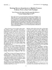
(1) a task node, encapsulating a procedure or a program, is de ned by its input/output data; (2) a task node, encapsulating another task node or a collection of task nodes, is de ned by its input/output data and a directed graph in terms of task=>task control edges; (3) a task ow is a directed graph that intersects the task data ow graph and the task data control graph; (4) an executable program can be written by creating a (hierarchical) task ow as an interconnection of tasks and data. Programs to `enable/disable' the state of task=>task edges are short and simple and are an integral part of the task node encapsulation. Most task=>task edges remain in the 'enabled' state by default and require no programming. Similarly, the data->task and task->data edges are always `enabled'. A hierarchy of task control ows and an instance of a task ow is shown in Figure 1. This example illustrates a representative program whose purpose, functionality, and implementation will be described later. Each task control ow has the four attributes of the program described in generic terms at the beginning of this section: (1) the sequence of tasks, expressed by enabled task=>task control edges. To invoke a task, the control edge incident at the task node must be enabled. (2) the decision about tasks to be executed, expressed by task=>task control edges that may be enabled/disabled, subject to conditions created by tasks executed earlier. Two such edges are rooted in the task evaluate treatment. (3) the repetition of a task, subject to terminating conditions for the task control self-loop. The task single treatment is shown with a self-loop. (4) the encapsulation of task nodes into another task node. For example, node Treatment C encapsulates three tasks, including single treatment, which in turn encapsulates three more tasks: apply C, evaluate treatment, and compress results. Inspecting the representations of single treatment as the task control ow and the task ow demonstrates that the task ow is indeed an intersection of the task control ow and the task data ow. The task data ow itself is a directed bipartite graph where all edges are static, i.e. always `enabled', and have two directions: data->task and task->data. In order to accommodate the data of type `inout', data nodes of type `input' are also represented as aliases of type `output'. Illustrative Example. The hierarchy of task ows in Figure 1 is based on the implementation of a program that captures the control and data description in a uni ed collaborative, networked task ow-oriented (CNT) task ow structure. More details about this structure are given in sections that follow. The speci c purpose of this program is to create an experimental design environment for a team of distributed collaborating participants whose main tasks are shown in doeFlow of Figure 1: � Generate classes task engages D. Ghosh to create classes of graphs that will test the performance of placement and routing algorithms used in the design of IC circuits [12]. The software to generate the classes and the class archives are on the server vela.cbl.ncsu.edu.
begin = download_class Task control flow instance download begin = doeFlow begin = Treatment_C Generate_ Classes
AAA AA AAA AA AAA AAA download_ class
Treatment_A
Treatment_B
Generate_ Summary
Publish_ Report
Treatment_C
single_ treatment
upload_ results
end = Treatment_C end = doeFlow
uncompress
install end = download_class
Task flow instance
begin = single_treatment
begin = single_treatment a
AA AA AA AA AA AA AA apply_C
b
evaluate_ treatment
c
compress_ results
end = single_treatment
d e
f
AA AA AAAA AA AA AA apply_C
evaluate_ treatment
compress_ results
end = single_treatment
Fig. 1. An expansion of a task control ow hierarchy and an instance of a task ow.
, Treatment B, Treatment C engage three research teams to develop and evaluate algorithms in the area of placement and routing, e.g. M. Stallmann's team, on euler.eos.ncsu.edu, is working on graph placement for crossing number minimization [13]. Each team expands the tasks into three subtasks: download class, single treatment, and upload results. The subtask single treatment expands further into apply C, evaluate treatment, and compress results. Here the infrastructure of tasks for Team A, Team B, Team C is identical { each team is only concerned with developing the speci c algorithm, here labeled as apply A, apply B, and apply C respectively. � Generate summary task is assigned to H. Lavana, working on gemini.cbl.ncsu.edu. � Publish report task is assigned to F. Brglez, working on zodiac.cbl.ncsu.edu. The project scenario of the experimental design project as outlined above is realistic. Its rst implementation did not have the bene t of the hierarchical structures; more details are available in [2]. With some simpli cation, the example is well suited to introduce and illustrate our current implementation of the taskfow-oriented programming concepts. Participants in the experimental design project are expected to work in a stand-alone or asynchronous mode for much of the time; only occasionally would the project leader convene a meeting of distributed participants to execute the entire task ow in a synchronizing mode. The asynchronous mode implies that participants can invoke only the programs they own, using data they own. We achieve such control by introducing two types of control edges for each ow graph: program-de ned control edges and user-de ned control edges. The state of the programde ned control edges is subject to conditions evaluated after task execution as described earlier, the state of the user-de ned control edges can be changed by the user via a graphical user interface. A brief overview of the GUI features and environment, � Treatment A
one expects to be supported when creating and executing a task ow-oriented program, is described next. III. Graphical User Interface
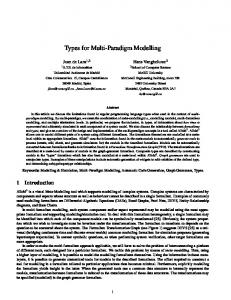
We describe the graphical user interface in two parts: (1) user-view of the experimental design task ow described earlier, now executed in the OmniFlow client; and (2) librarian-view, using an XML editor during the creation of the experimental design task ow. User-view of the task ow. The hierarchy of task ows in Figure 1 is displayed in the tree browser shown as the left-most part of Figure 2. In a tree browser, and at any given level of hierarchy, it is di�cult to represent task node dependencies. Using the tree browser, user can select and load any task ow and display it as a graph. Two such graphs are shown: one represents the task node dependencies for the task ow treatment C, whereas the node Single Treatment is expanded into another task ow (following the illustration in Figure 1). Consider rst the task ow treatment C. The graph is always acyclic and no nodes are isolated; the edges shown are control edges. Each control edge has two states: we say that the edge task=>task is the `enabled', and the edge task==task is `disabled'. User can click on any control edge to enable and disable its state. A task node with incoming control edges that are disabled can never be invoked by other task nodes. However, if the task ow is in the execute mode, user can invoke the task node by simply clicking on it. The ow itself is depicted in the state where the two top-most nodes have completed execution, shown by the darkened rectangles at the head of the control edges. This includes a number of iterations of the second task, controlled by the self-loop control edge. Other task nodes, reachable from a given node, may also be automatically invoked, depending on the settings of the user-de ned edges. The nodes BEGIN and END are primitive task nodes, the nodes enclosed in bold boxes are hierarchical task nodes. With each task node, we associate 0 or more
Fig. 2. Task ow hierarchy, task ow selection, and task ow execution in OmniFlow.
data node inputs and outputs. These are represented as small circles and ingoing/outgoing edges within the bold box of the task node. When two tasks depend on the same data node, a data node may be shared by more than one task node, either as an input or as an output. Such dependencies are not shown explicitly in this representation, however they are declared in the XML description of the task ow and maintained during the task ow execution. The task ow Single Treatment on the right-most side is an expanded view of the hierarchical node in treatment C. There are two outgoing control edges from the Eval Treatment task. In addition to user-de ned state of these two control edges, their state is controlled also by status of postconditions evaluated during the last phase of the Eval Treatment task. If user left both edges in the `enabled' state, either or both may be disabled by the postconditions. However, if user left both edges in the `disabled' state, then the state of these edges cannot be changed by the postconditions. Note also that there are two incoming control edges to the node END. Here, in the rst phase and before invoking the task, we evaluate WaitConditions status of all incoming control edges. The task is invoked only if the WaitConditions status is true. In the example shown, the control edge Eval_Treatment => END has been disabled by the user prior to the task ow execution. With this con guration, (1) the Single Treatment task ow completes only
if Compress Results task has been invoked and completed, and (2) the Single Treatment task node triggers the invocation of the Upload Class only when the Single Treatment task ow completes. Librarian-view of the task ow. The task ow con guration that generated user-view in Figure 2 is an XML document. As such, it could have been created by a task ow librarian with or without using an XML editor. However, the preferred choice is to use an XML editor, and the reason is clear once we examine the interface as shown in Figure 3. The entry of the task ow con guration is well-structured, moreover, we get the bene t of the validating editor. Consider the task ow treatment C as shown. First, for TaskFlow we enter the name, inputs, outputs, and graph. The graph is a connected DAG, consisting of a number of task nodes connected by user-de ned control edges. The simple format we use has been described in [14]. Second, we list (in any order) the task nodes and their attributes such as le locator (href), host, and protocol. Third, for each task node we specify data elements and control elements. The data elements consist of data input pairs and data output pairs, listed under AliasInput and AliasOutput. The control elements consist of WaitConditions, LoopConditions, and PostConditions. In the example shown, the loop conditions for the Single Treatment task are controlled by ForEach parameters.
Fig. 3. A view of a CNT task ow in an XML editor.
For completeness, we also display the XML source le of treatment C in Figure 4. The le is well-structured and the major advantage of the XML editor is the validation of its syntax during editing. On the other hand, consider that a task ow itself, upon execution, may generate an XML description of another task ow. The XML schema that determines the structure of such and any other CNT task ows les is introduced in the next section. IV. CNT Structure: An Overview
A document in a mark-up language such as XML is structured like an object model: it supports a wellde ned schema [15] that can capture the decomposition of any project or any program into a hierarchy of tasks. A schema that implements a hierarchical collaborative, networked task ow-oriented CNTML structure, proposed in this paper, is shown in Figure 5. At the top level, we have two elements: single occurrence of MainTasks or multiple occurrences of TaskFlow elements. The MainTasks element invoke any number of MainTaskNode and MainPrimitiveNode elements, each of which relies on a Data element and its attributes. A MainTaskNode instantiates a TaskFlow by reference. The attributes of the TaskFlow are inputs, outputs, and graph, while its elements are single occurrences of (BeginNode, EndNode) and multiple occurrences of TaskNode or PrimitiveNode. Both of the latter rely on a Data element as well as a Control element and
the respective attributes. Since a TaskNode may itself be hierarchical, it can instantiate another TaskFlow by reference. A precise de nition of an XML schema requires a textual rather than a graphical description. However, since the standard is still evolving and validating parsers for XML schemas are not yet readily available [15], we use Document Type De nition (DTD) format to describe the CNTML schema { it requires less than 2 pages and is available as an Appendix in [16]. A segment of this schema in DTD format is shown in Figure 6. This segment of the XML schema provides details about the TaskFlow element that could not be addressed by the illustration in Figure 5. Speci cally, we note that the attributes of task ow name, inputs, outputs, graph all require CDATA descriptions and that the attributes for TaskNode and PrimitiveNode are identical. Default values are entered for attributes named wkdir (working directory), host, and owner. Except for attributes of row and column that allow the user to control the position of the node in the graphical user interface, all other attributes of TaskNode are self-explanatory, with full details provided in [16]. An example, illustrating the syntax to evaluate the PostConditions, is shown in Figure 7. V. CNT Scheduling and Execution
Consider the doeFlow in Figure 1. It consists of a hierarchy of task ows captured as instances of task nodes.
(classname) (classzip) (class_files) (ckt_name) (classname) (trtC_zip) (ckt_name) [(class_files)] (trtC_zip) (up_trtC_zip)
Fig. 4. A view of a CNT task ow in a plain text editor.
AAAAAAA AAAAAAA AAAAAAA CNTML AAAAAAA AAAAA AAAAA AAAAAAA AAAAA AAAAA AAAAAA AAAAA AA AAAAA AAA AAAAAA AAAAAAA inputsAAAAAAA AAAAAAA AAAAA AA AAAAA AAA AAAAAA AAAAAAA AAAAA AAAAA AA AAAAAAA AAA AAAAAA AAAAAAA outputs AAAAAAA AAAAAAA AAA AAAAAAA AAAAAA MainTasks TaskFlow AAA AAAAAAA AA AAAAAAA AAAAAA graph AAA AAAAAAA AA AAAAAAA AAAAAA href AAA AA AAAAAA AAAAAAAA AAAA AAA AAA AA AAAA AAA AAAAAAAA AA href AAAAA BeginNode AAAAA AAAAAAAA AAA AAAA AAA AAAAAAAA AA AA AAAAAAA Data AAA AA AAAA AAA AAA AAAAAAAA AAAAA AAAAAAAA AA AAAAAAA MainTask AAA AA AAAA AAA AAAAA AAA AAAAA AAAAAAA AAAAAAAA AAAAA AAA AAAAAA AA Node TaskNode AAA AA AAA AAAAAA AAAAA AAA AAAAAAA AAAAA AAA AAAAAAAA AAAAA AAA AAAAAA AA Control AA AAA AA AAAAAAA AAAAA AAA AAAAAA AAAAAAAA AAAAA AAA AAAAAA Data AAA AAAAA AAA AAAAAA AA AA AAA AAAAAA AAAAAAAA AAAAAAAAA AAA AAAAA AA AAAA AAA AAAAAA AA AAA AA AAAAA AAAAAAAA AAA AAAAAAAAA AAAA AAA AA MainPrimitive AAA AAAA AAAAA AA AAAA AAA AA AAA AA AAAAA AAAAAAAA AAA AAAAAAAAA AAAA AAA AA PrimitiveNode Node AA AAA AAAAAAA AAAA AAAAA AAAAAAAA AAA AAAAAAAAA AAAA AAA Data AA AAAAA AA AAA AAAAA AAA AAAAAAA AAAA AAA AAAAA AAAAAAAA AAAA AAA AAAAA AA AAAAA AAA AAAAA AAA AAAAAAA AAA AAAAA AAAAAA EndNode AAAA Data AAAAA AAAAA AAAAAA AAAAAAAAAAA AAAAAAAAA AA Control AAAAAAAA AAAAA AAAAA AAAAAAA AAAAAA AA AAAAA AA AAAAAAAA Fig. 5. XML schema of a CNT declaration.
Fig. 6. A CNT task ow DTD invoked by OmniFlow. GreaterThan 5 LessThanOrEqualTo 5
Fig. 7. PostConditions for TaskNode Eval Treatment.
The three task nodes, Treatment A, Treatment B and Treatment C in doeFlow are independent of one another and hence can be invoked concurrently. However, all the three task nodes have to wait for the task node Generate Classes to complete before any of them can be invoked. Similarly, the task node Generate Summary cannot be invoked until all the three treatments have been invoked and completed. In addition, each of the three treatment needs to be invoked on a di�erent host, speci c to where the associated treatment is accessible. The doeFlow thus represents a distributed task ow that requires concurrent, asynchronous invocation of its task nodes. A formal approach is necessary to schedule and execute such a task ow. We use Petri net model [17] to implement the scheduling algorithm that executes the hierarchical task ow. We next describe the execution of the doeFlow, as depicted in Figure 1. First, all the task nodes in the doeFlow are initialized to a `wait' state. We invoke the doeFlow by assigning a `completed' state to its BEGIN node. This results in evaluation of the WaitConditions for the task node Generate Classes, thereby changing its state to `enabled'. Once enabled, and if the task is available, the task is red. Upon task completion,
tokens are passed on to the task nodes Treatment A, and Treatment C for evaluation by the WaitConditions. Assuming that the WaitConditions for task node Treatment C evaluates to true, the node changes to the `enabled' state. Since the task node Treatment C is a hierarchical task ow, it is immediately invoked and expanded into its corresponding task ow which consists of three task nodes: download class, single treatment and upload results. As these nodes are invoked in sequence, each expands into subtask ows. The single treatment task node expands into three primitive tasks. When the task ow invocation reaches a primitive task, such as apply C that can no longer be expanded, it schedules the task associated with the primitive node for execution on the speci ed host. The speci ed host executes the task apply C only after it becomes idle and is not processing any other tasks. On its completion, the PostConditions of apply C are evaluated so that its output program-de ned control edges can be enabled. When the task node compress results has completed its execution, the task ow single treatment, which was expanded initially for invocation, is closed and is assigned a `completed' state. In a similar fashion, the remaining task nodes in the task ow Treatment C are invoked and upon their completion, the expanded hierarchy of Treatment C in doeFlow is closed and a `completed' state is assigned to it. In the doeFlow, however, the task node Generate Summary cannot be invoked until all the three Treatment A, Treatment B and Treatment C have been assigned the `completed' state. Finally, the task node Publish Report is invoked to publish a report of the summarized results. A formal description and more details about implementation in general and the scheduler in particular are available in [16]. Treatment B
VI. Conclusions
In this paper, we have merged simple and well-known concepts from three areas: structured programming, hardware description, and mark-up languages. Hardware description languages and structured methodologies play a major role in supporting the productivity and advances in the design of complex systems that routinely package millions of transistors onto a single IC. The rapid advances in XML technology for the Web will continue to evolve and amplify the approach proposed in this paper. In our experience, the approach we presented provides freedom and exibility we lacked in our earlier work on distributed collaborative computing. The exibility to decompose and organize each project into a hierarchy of tasks, and the ability to quickly recon gure the control of task execution from a single task to selected few, provides new perspectives on end-user programming and modes of collaboration. Applications of the proposed concepts to areas other than those presented in this paper are needed to round the experience in what may become a new paradigm for e�ective distributed and collaborative computing.
[1]
[2]
[3] [4]
[5] [6] [7] [8] [9]
[10] [11] [12]
[13]
[14] [15] [16] [17]
References H. Lavana, F. Brglez, R. Reese, G. Konduri, and A Chandrakasan. OpenDesign: An Open User-Con gurable Project Environment for Collaborative Design and Execution on the Internet. IEEE Intl. Conference on Computer Design, 2000. Also available at http://www.cbl.ncsu.edu/publications/#2000-ICCD-Lavana. F. Brglez, H. Lavana, D. Ghosh, B. Allen, R. Casstevens, J. Harlow III, R. Kurve, S. Page, and M. Stallmann. OpenExperiment: A Con gurable Environment for Collaborative Experimental Design and Execution on the Internet . Technical Report, March 2000. Available at http://www.cbl.ncsu.edu/publications/#2000-TR@CBL-02-Brglez. S. Page. Openwriter: Client/server utilities for collaborative writing environment, 2000. A senior project report. Computer Science Department, NC State University. For more information, see http://www.cbl.ncsu.edu/OpenProjects/OpenWriter/. F. Brglez, H. Lavana, Z. Fu, D. Ghosh, L. I. Mo�tt, S. Nelson, J. M. Smith, and J. Zhou. Collaborative Client-Server Architectures in Tcl/Tk: A Class Project Experiment and Experience. In Seventh Annual Tcl/Tk Conference. USENIX, February 2000. Also available at http://www.cbl.ncsu.edu/publications/#2000-TclTk-Brglez. F. Brglez and H. Lavana. CollabWiseTk: A Toolkit for Rendering Stand-alone Applications Collaborative. In Seventh Annual Tcl/Tk Conference. USENIX, February 2000. Also available at http://www.cbl.ncsu.edu/publications/#2000-TclTk-Lavana. S. Bocionek and K. Fischer. Task-oriented programming with co-operating rule-based modules. Engineering Applications of AI, 2:207{213, 1989. H. Friedrich, S. Munch, R. Dillman, S. Bocionek, and M. Sassin. Robot programming by demonstration (RPD): Supporting the induction by human interaction. Machine Learning, 23:163{189, 1996. A. Rifkin. Speci cation, implementation, and reasoning about task-oriented distributed system components, 1997. A PhD thesis proposal. For more information, see http://www.cs.caltech.edu/ adam/phd/aug97/thesis.html. H. Lavana, A. Khetawat, F. Brglez, and K. Kozminski. Executable Work ows: A Paradigm for Collaborative Design on the Internet. In Proceedings of the 34th Design Automation Conference, pages 553{558, June 1997. Also available at http://www.cbl.ncsu.edu/publications/#1997-DAC-Lavana. D. Gajski and A. Wu and N. Dutt and S. Lin. High-Level Sythesis Introduction to Chip and System Design. Kluwer, 1992. D. Wallace . Low Level Scheduling Using the Hierarchical Task Graph. In International Conference on Super Computing, 1992. Debabrata Ghosh. Generation of Tightly Controlled Equivalence Classes for Experimental Design of Heuristics for Graph{Based NP-hard Problems . PhD thesis, Electrical and Computer Engineering, North Carolina State University, Raleigh, N.C., May 2000. Also available at http://www.cbl.ncsu.edu/publications/#2000-Thesis-PhD-Ghosh. M. Stallmann, F. Brglez, and D. Ghosh. Heuristics and Experimental Design for Bigraph Crossing Number Minimization. In Algorithm Engineering and Experimentation (ALENEX'99), number 1619 in Lecture Notes in Computer Science, pages 74{93. Springer Verlag, 1999. Also available at http://www.cbl.ncsu.edu/publications/#1999-ALENEX-Stallmann. E.R. Gansner, E. Koutsi os, S.C. North and K.P. Vo. A Technique for Drawing Directed Graphs. IEEE Trans. Software Engg., 19:214{230, 1993. Software available from http://www.research.att.com/sw/tools/graphviz/ . W3C Home Page for XML Schema, September 2000. For more information, see http://www.w3.org/XML/Schema.html. F. Brglez and H. Lavana. Task ow-Oriented Programming: A Paradigm for Distributed Collaborative Computing. Technical Report, October 2000. Available at http://www.cbl.ncsu.edu/publications/2000-TR@CBL-05-Brglez. T. Murata. Petri Nets: Properties, Analysis, and Applications. Proceedings of IEEE, pages 541{580, April 1989.