The Task-Resource Matrix: Control for a Distributed Reconfigurable Multi-Processor Hardware RTOS Spencer Isaacson
Doran Wilde
Intel Corporation 1900 Prairie City Rd. Folsom, CA 95630 (916)356-224
[email protected]
Brigham Young University Dept. of Electrical and Computer Engineering Provo, UT 84602 (801)422-8739 FAX: (801)422-0201
[email protected]
Abstract Real-time embedded systems are being built more and more as Systems on a Programmable Chip. Better predictability and faster execution times can be achieved by moving functions traditionally implemented in software to specialized hardware. The Task Resource Matrix developed at Brigham Young University gives hardware more control in administration of tasks and communication primitives by providing mutual exclusion, synchronization, and task operating state. When coupled with a hardware scheduler and the Real-Time Processor, the Task Resource Matrix can be configured to support specific real-time applications.
1. Introduction It is becoming common for processors, memory, and custom hardware to all be integrated on a single System on a Chip (SoC). Advances in Field Programmable Gate Arrays (FPGAs) such as the Xilinx Spartan 3 and Virtex II [4] have made it possible to design powerful and easily customizable Systems on a Programmable Chip (SoPCs). Several recent innovations in hardware/software codesign target SoCs in an effort to improve embedded system performance and design [1, 2, 3]. As FPGAs increase in gate count and memory capacity, SoPCs will continue to increase in popularity. Implementing a function in specialized hardware, rather than in software running on a general purpose processor, is faster and more predictable [5]. On an FPGA, where hardware elements are abundant and memory space is limited, it is the software that is more expensive, giving specialized hardware functions the triple benefit of being faster, more predictable, and cheaper. Previous work has shown numerous advantages of implementing a Real Time Operating System (RTOS) in hardware [5,6,7]. With abundant hardware resources, an FPGA is a perfect target for a hardware based OS.
Implementing an RTOS primarily in hardware mitigates a primary weakness of FPGAs: the lack of memory space. Traditionally inter-task communication and synchronization are accomplished through the use of data primitives implemented in shared memory and controlled by the RTOS. These primitives are not only costly in processor cycles, but are also costly in memory usage. Moving communication and synchronization primitives to hardware not only saves memory but processor cycles. The Real Time Processor (RTP) project aims to provide a new architecture for embedded system codesign. The system architecture includes an advanced task and resource management structure called the TaskResource Matrix (TRM) that implements the synchronization primitives in hardware for a variety of resource types. This paper is organized as follows: Section 2 describes the RTP architecture. The TRM is described in more detail in Section 3. Section 4 gives a brief history into the research conducted in this area. Concluding remarks as well as future work is given in Section 5.
2. The RTP Architecture The RTP architecture aims to create a simple to use customizable embedded system utilizing fast inter-task and inter-processor communication, fast context switching, and RTOS all implemented in hardware. The final design goal is a multiprocessor real-time embedded system on a single programmable chip. An ideal processor would therefore have enough power to run multiple tasks with reasonable performance, yet be lightweight enough that several could easily fit on a single FPGA. Current soft processors that provide sufficient power, such as the Xilinx Microblaze, are too large and too slow. The Microblaze [4] requires 1050 slices on a Spartan 3, with a 32x32 bit register file. Smaller, 8-bit microcontrollers such as the Xilinx Picoblaze have inadequate power and code capacity to run any but the simplest of applications; with the limit of
addressing 1024 instructions, it is unlikely the Picoblaze could handle more than one task. The following compromise specifications were developed for a processor to run the RTP system: 18-bit instructions, 12bit instruction address capability, 16-bit data memory
Processor MicroBlaze RTP PicoBlaze
address capability, 8 bit general purpose I/O (GPIO) address , 16-bit arithmetic, with instruction support to perform larger than 16-bit arithmetic, and a target size of 400 slices when running 1 task as shown in Table 1 below.
Table 1: A comparison of Soft Processors Address Size on Instruction Size Register File Capability Spartan 3 32-bit 32-bit 32x32b 1050 slices 12-bit inst 18-bit 16x16b 400 slices 16-bit data 8-bit GPIO 16-bit 10-bit 16x8b 84 slices
Designing a custom processor also allows tailoring of the instruction set that allow instructions that interface with custom RTOS hardware much more efficiently than with a standard instruction set. Resource specific control instructions in this new architecture include the following: LOCK r: Attempt to reserve system resource r. If unsuccessful, the task is blocked until the resource becomes available. NB-LOCK r: (non-blocking lock) Attempt to reserve system resource r without blocking. Return information about the task that has locked the requested resource. Using this information, a task can determine if it successfully locked the resource, or if not, what other task has locked the resource. REL r: Release system resource r so other tasks may reserve it. RST r: Reset system resource r to initial state. The meaning of the following instruction varies for each resource type: ENABLE r: Enable system resource r. DISABLE r: Disable system resource r. SIG1 r: Send signal 1 to system resource r. SIG2 r: Send signal 2 to system resource r. READ r: Read the status of system resource r. WRITE r: Write to the status of system resource r. Task specific control instructions include the following: R_PRIO: Read task information about the current task and store it in a register. This information includes task ID and task priority. W_PRIO: Write the task information stored in a register to a specified task. This is used primarily for priority inheritance. R_TIME: Read the current task’s timeout counter.
Arithmetic 32-bit 8/16/32-bit 8-bit
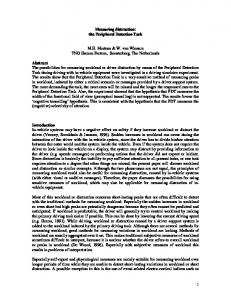
W_TIME: Write a value to the timeout counter of the current task. These custom instructions facilitate hardware assistance to the RTOS, resulting in a much smaller software kernel. The software kernel has been reduced to 335 instructions. The custom instructions control resources and tasks in the TRM (described in the next section), that, along with a hardware scheduler, determines which task will run on a processor at any given time. Figure 1 shows an overview of the RTP architecture. The architecture is a multiprocessor system, containing an array of 1 to 16 processors. Task state is maintained for each task running on a processor. Information stored for each task includes a separate register set, program counter, and flags. Context switching is done by providing a task id to the processor. The task ID selects which task state to use while executing an instruction. Switching contexts in this manner precludes dynamic task creation and deletion. The architecture is also limited to a maximum of 16 tasks per processor. More tasks can be hosted by using additional processors. The small footprint of the RTP encourages the use of multiple processors. Each processor has its own local memory for code and data, shared by all tasks on that processor. Each processor also has its own local I/O space of up to 256 ports. A 16-bit local I/O bus is connected to all of the peripherals used by that processor, such as serial ports, queues, and network interfaces. Peripherals that can be shared by two or more tasks, whether they are on a single processor or on different processors, need to be synchronized among the competing tasks. This is done using system “resources” in this architecture. System resources include mutexes, semaphores, timers, interrupt sources, and similar types of circuits that help manage shared resources of any type. Resources can be locked by a single task if mutual exclusion is required.
Output
Processor
I/O Devices
Queue
Input
Local I/O Bus Non-shared device
Shared Memory
Processor
Non-shared device Local I/O Bus Non-shared device
Queue Processor
Local I/O Bus Interrupt
Scheduler
Global Resource Bus
Resource Module
Resource Module
Resource Module
Resource Node
Task Module Task Module
Resource Module
Resource Node
Resource Node Resource Node
Resource Node
Resource Node
Task Module Task Module
Resource Node
Task Module
Resource Node
Resource Node Resource Node
Task-Resource Matrix
Figure 1: The RTP Project Architecture RTP
addr (12 bit) ⇐ data (16 bit) ⇔ data memory write_high ← write_low ← addr(12 bit) ⇐ intsruction memory enable ← instruction(18 bit) ⇒ scheduler { task_id(4 bit) ⇒
⇒ addr (8 bit) ⇔ data (16 bit) I/O Device Interface → read strobe → write strobe ⇒ resource addr (8 bits) ⇒ task - proc addr (8 bits) Task - Resource → TRM request ← TRM grant → enable → disable → sig1 → sig2 Resource control → read → write → reset → release → read timer → write timer Task control → read priority → write priority → lock
→ nblock Node control → release
Figure 2: RTP Interface
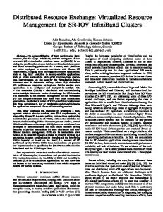
The TRM, shown in figure 1, is an innovative feature of this architecture that controls the sharing of resources in a unified way. It contains a “resource node” for each task needing access to a resource. The resource node keeps track of pending requests and grants for a resource. This new circuit provides important hardware assistance to the RTOS by keeping track of the tasks that are waiting for specific resources. The TRM provides information to the scheduler about what tasks are “blocked” waiting for any un-granted resources. A shared global resource bus is used to access system resources and task modules. Since this bus is shared, processors must arbitrate to use it. The processor interface is designed to operate with the TRM as well as communicate with resource modules and peripherals. Figure 2 diagrams the processor interface. Listed are all the inputs and outputs of the Real-Time Processor (RTP). The signals are grouped according to the block with which it interfaces. The groupings of signals include interfaces to instruction memory, data memory, and I/O device. Connections to the TRM include three sub-interfaces: resource control, task control
and node control. Each of these interfaces is described in more detail below. The dedicated input from the scheduler is the task ID of the highest priority ready task for that processor.
the connections are used with every resource; some of the signals may not have meaning. The following resource modules are implemented for use as part of the RTP project:
3. The Task-Resource Matrix
Mutex A mutex can be declared for any shared device. Before accessing a shared device, a task must acquire the mutex lock. Once locked, the task has exclusive privileges to the shared resource. When access to the resource is no longer required, the task releases the mutex lock.
The Task-Resource Matrix is organized by rows and columns. The rows represent tasks interfacing with the TRM and the columns represent resources. A task sends a signal to the TRM to lock or reserve a resource for exclusive use. If the resource lock is granted, the task may continue executing and use the resource. If the lock is not granted, the TRM signals the scheduler to block that task from executing. Additionally, a peripheral may send status information to the TRM. For example, if a queue resource is full, it signals the TRM not to grant access until the queue no longer sends the full flag. The resource nodes in the TRM keep request/grant state of a task for a particular resource.
3.1. Types of Resource Modules The resource modules maintain the state of the resources they represent. In order to simplify system generation, a standard resource module interface is used. Figure 3 shows this interface. resource addr ⇒ data ⇔ enable → disable → sig1 → Processors sig 2 → read → write → reset → release →
Resource Module Interface
← Resource specific input from device → select ← inUse Node Interface → free
Figure 3: Resource Module Interface The interface includes signals from the processor, any resource specific inputs and an interface with the resource nodes. The resource address specifies which resource is targeted; the data bus transfers any resource specific information. The remaining signals originating from the processor are control signals asserted directly as a result of executing hardware control instructions previously discussed. The signal free indicates that this resource can be locked by another task. The inUse signal indicates that one or more tasks have locked the resource. The select signal is broadcast to all nodes corresponding to this resource. It signifies that this resource is targeted for action by the processor. The resource specific input from a peripheral varies depending on the resource. Not all of
Event An event is a set of flags that enables the granting of a lock. A conjunctive event requires all of the flags to be set. A disjunctive event requires any one of the flags to be set. When an event is detected, a lock will be granted to the highest-priority requesting task. The task can then clear the event flags. Semaphore This resource is associated with a counter. This resource may be locked (and the count atomically decremented) by multiple tasks as long as the counter is strictly positive ( ≥1 ). Tasks can also initialize the counter. Interrupt Using the task-resource matrix, interrupts are serviced like any other event in RTPOS. On system initialization, an interrupt service routine is initialized and then blocks, waiting for an interrupt. When an interrupt event occurs, the interrupt lock is granted and the service routine proceeds. The interrupt routine releases the lock (rearming the interrupt), services the interrupt, and then tries to re-acquire the lock, thereby blocking until the next interrupt event. Reader Before reading a queue (or mailbox, etc.), a task must acquire a read lock. This lock is only granted if the queue is not empty. Once locked, the task has exclusive read privileges and can read multiple words. When done, the task releases the read lock. Writer Before writing a queue (or mailbox, etc.), a task must acquire a write lock. This lock is only granted if the queue is not full. Once locked, the task has exclusive write privileges and can write multiple words. When done, the task releases the write lock. Global Timer This resource may be locked by multiple tasks if the timer is zero. The timer may be read and written. Tasks that
try to lock a non-zero timer will block until it decrements to zero. It is decremented every millisecond.
3.2. The Task Modules The task module contains information such as its taskprocessor id, priority, ready state, and timeout counter. The timeout mechanism allows a task to set a time-limit for which it will wait for a resource. This timeout counter can also be used as a suspend resource for each task. Using this counter, a task can suspend itself for a specified amount of time or indefinitely. The priority can be dynamically changed to support operations such as priority inheritance to solve the priority inversion problem. Figure 4 details the connections to a task module. task - proc addr ⇒ Task data ⇔ Module read timer → Interface ← ready Processors write timer → ← lockednode interface read priority → → select write priority → Scheduler { ready ←
Figure 4: Task Module Interface The task module interface is also standardized in order to facilitate system generation. The processor specific connections include a task-processor id that addresses the correct task module for use, and a data bus. The remaining signals originating from the processor are control signals asserted as a result of executing hardware control instructions previously discussed. The node interface includes ready, locked and select signals. The ready signal alerts the task module and subsequently the scheduler that there are no outstanding resource requests that block execution. The locked signal is a logical or of all the selected locks in a task row. The locked signal is used by the nb_lock instruction to identify which task holds a resource. The currently executing task determines the select signal that is used to select a task row for modification by the processor.
3.3. The Resource Node The resource node is found at intersections of task rows and resource columns. The nodes are sparsely populated and only placed where a task depends on a resource. In this way, only useful circuitry is built. Figure 5 shows the resource node interface.
ready_out ← Task Module locked_out ← select → inUse_in → free_out ← lock → nblock → Processor release → reset →
Resource ← ready_in ← locked_in Node Interface ← select
→ inUse_out Resource Module ← free_in
Figure 5: Resource Node Interface The resource node keeps track of pending requests and grants for a resource. The node maintains the state by keeping a request flag and a grant flag. Control signals such as lock, nb_lock, and release modify the state of the node. On a lock, the request flag is set. The task will block until the lock is granted (i.e. the request flag is reset and the grant flag is set) or until its timeout counter expires. The request flag is used in combination with the ready_in signal to generate the ready_out that will eventually propagate to the task module. While the request flag is asserted, the node will signal the task module and scheduler to remove the task from the ready queue. If the resource is free to acquire, the lock is immediately granted without stalling the task. On an nb_lock signal, the task will never stall. The state of the resource and the task ID of the task that has locked the resource are returned to the processor. If the task is free to acquire, the grant flag will be set. If not, there is no change in state. A release signal releases the lock held by the task by resetting the grant flag. The reset signal resets both the request and grant flags. The inUse signal is chained through all the nodes connected to the same resource to the resource module and signifies that some task has locked the resource. The free signal originates in the resource module and is chained through resource nodes. It signifies that this resource is free to lock. It also prioritizes which task gets the grant when multiple tasks are requesting the resource. The ready and locked signals chain together nodes in the same task row. Ready is the logical NAND of all the request flags in the row and is used to remove the task from the ready queue. Locked is an logical OR of the selected grants used by the nb_lock instruction to identify which task holds a resource. The confluence of the task and resource select lines enables a node state change. There are three main types of resource nodes: a single acquisition node, a multiple acquisition node, and an interrupt node. A single acquisition node assures that only one task maintains ownership of any given resource at any given time. A multiple acquisition node allows multiple locks to be granted. While the first two types of resource node differ only in the connections between nodes and modules, the third type of resource node is markedly different and serves a different purpose.
The interrupt node should only be used by tasks that are Interrupt Service Routines (ISR). In general, ISRs should not depend on shared resources. A traditional interrupt event typically triggers a jump to an ISR address in the interrupt vector table. The traditional ISR saves context, does some sort of decoding to ascertain what interrupt request (IRQ) triggered the event and services the event. In the RTP architecture, an IRQ is handled by an interrupt resource. The task that is designated an ISR for a particular IRQ depends on the interrupt resource associated with that IRQ. On startup, the ISR runs initialization code and then attempts to lock the interrupt resource. Unless the interrupt event has already occurred, the ISR will block. On an interrupt event, the ISR unblocks, re-arms the interrupt resource module and runs until it retries to lock the interrupt resource. If an interrupt occurs while the ISR is running, the resource module remembers an event has occurred and immediately grants the lock. There is no interrupt vector table; there is no saving and restoring of context. Using this method of interrupt handling within the scope of the RTP architecture allows a designer to guarantee a number of cycles before an interrupt is serviced. The resource modules and resource nodes vary for each type of resource. However the interconnections between them are standard. The task modules also interface with the resource nodes in a standard fashion, although, some of the connections may be left unused. The goal of standard connections is to simplify system generation. The combination of resource module, task module, and resource node allows fast inter-processor communication to take place. For example, a typical mutex release may result in a context switch. The entire process of task switching from mutex release to a new task running requires only 4 clock cycles. During the first cycle, a task sends a release command to the TRM targeting the specified mutex. On the next cycle, the release is processed, a pending task is granted the mutex, and the task module is signaled that the grant has been completed. Arbitration through the scheduler takes place during the third cycle. On the fourth cycle, instructions from the newly readied task are fetched for execution on the processor. From the point of view of the processor, no cycles are lost. During cycle three, instructions are fetched from the previous highest priority ready task, but during cycle 4, the task switch is complete; instructions are fetched to execute the new task.
4. Related Work The new architecture requires new tools to exploit its technological advances. A C compiler developed as part of the RTP project allows the user to develop the system
using ANSI-C code. A hardware generator developed also speeds development time and eliminates human error by automating system generation using a correct-byconstruction methodology. The details of this compiler/generator are included in a forth-coming paper. The hardware RTOS mentioned in this paper is detailed in a forth-coming paper as well. The idea of keeping separate register sets to speed up context switches is not new. The SPARCLE processor, introduced in [8], used four different register sets to store contexts. However, the PC and status registers must be saved by the trap handler. Our design provides totally separate contexts for up to 16 tasks, including the PC and status register. The switching between contexts is done by the hardware in our architecture, not in software as is done in the SPARCLE processor. In [9], context-switching time in a real-time system was reduced by one half by adding a register cache to a MIPS R3000 core in an ASIC. In the Silicon TRON project [10], the same authors used hardware to shorten system calls and scheduling. They provided modules for event flags, semaphores, timers, tasks, the scheduler, and a control module that interfaced with the CPU using an interrupt and status registers. This reduced the kernel RTOS code size by about 50%. Our project uses some of the same ideas. However, we have additional hardware to eliminate context-switching time altogether. We also have a sparse task-resource matrix to manage system resources. The current version of our software kernel used to interface with the hardware, which together make up our RTOS, is only 335 instructions. Our task-resource matrix is similar to the matrix described in [11]. That paper described a dense task-resource matrix that was used to detect deadlock via reduction of unused entries. A framework supporting multiprocessing was described in [12] and [13] that used a hardware generator similar to that being developed as part of the RTP project. In that framework, both Arm and PPC processors could be used, and inter-task communication used shared memory. By contrast, the system we have described here does not use shared memory for communication, but rather dedicated hardware fifos, queues, semaphores, etc. Also, our system uses a new processor that is extended with primitive resource management machine instructions. Current research proposed in [14] will investigate the co-configuration of an RTOS with a multiprocessor SoPC, with some RTOS-support functions done in hardware, but only proposes implementing synchronization primitives and function blocks such as semaphores and queues. The hardware RTOS implemented as part of the RTP project implements the majority of the kernel in hardware in a tightly coupled design with a customized microprocessor for optimum performance, rather than the more general RTOS configurable to a wider range of architecture as in [14].
5. Conclusions and Future Work Embedded system design is trending toward tighter integration. SoPCs play an important role in the future of embedded design. Research completed now will enhance our ability to benefit from future advances in FPGA and other reprogrammable device. By moving more of the functionality of an RTOS from memory, a scarce resource on an FPGA, to specialized configurable hardware, gains are made by having the system perform more predictably and faster. Moving system resources and task information storage to hardware allows for the creation of the Task-Resource Matrix, a simple yet effective way to interface tasks and resources and determine task state. Resource modules maintain state of resource primitives. Similarly, task modules maintain state information of tasks running on specialized processors. Communication between task modules and resource modules is maintained through resource nodes. Together, the resource modules, task modules, and resource nodes, which comprise the TRM, can grant mutual exclusion, provide information regarding resources or tasks, and block a task from running via specialized instructions. Coupled with the real-time scheduler also implemented in hardware, the TRM quickly provides the processor with the highestpriority ready task every clock cycle. Hardware to control context switching greatly reduces the amount of overhead associated with changing active tasks. Future work entails testing of the RTP architecture, including the TRM, targeted by embedded applications in a variety of sizes and with varying real-time deadlines. At the writing of this paper, an initial version of the RTP architecture was nearing completion and ready for testing. Future papers will detail the RTPOS, an RTOS targeting the RTP architecture, as well as a C compiler targeting the RTP instruction set architecture and a system generator to allow an application designer to quickly configure a custom system using the RTP architecture and the TRM.
6. References [1] V. Mooney and D. Blough, “A Hardware-Software RealTime Operating System Framework for SoCs,” IEEE Design & Test of Computers, pp. 44-51, Nov-Dec 2002. [2] V. Mooney, “Hardware/Software Partitioning of Operating Systems [SoC Applications],” Proc. of the Design, Automation and Test in Europe Conference and Exhibition, pp. 338-339, 2003. [3] M. Boden, J. Schneider, K. Feske, and S. Rulke, “Enhanced Reusability for SoC-based HW/SW Co-design,” Proc. of the
Euromicro Symposium on Digital System Design, pp 94-99, Sep. 4-6, 2002. [4] Xilinx, http://www.xilinx.com [5] J. Adomat, J. Furunas, L. Lindh and J. Starner, “Real-Time Kernel in Hardware RTU: A Step Towards Deterministic and High-Performance Real-Time Systems,” Proceedings of EURWRTS ‘96, pp. 164-168, June 1996. [6] Realfast, http://www.realfast.se [7] T. Nakano, Y. Komastudaira, A. Shiomi and M. Imai, “VLSI implementation of a Real Time Operating System,” Proc. of ASP-DAC ’97, pp.679-680, January 1997. [8] Anant Agarwal, John Kubiatowicz, David Kranz, Ben-Hong Lim, Donald Yeung, Godfrey D’Souza, and Mike Parkin, Sparcle: An Evolutionary Processor Design for Large-Scale Multiprocessors, IEEE Micro, Vol. 13 Issue 3, pp. 48-61, June 1993. [9] Jun-ichi Ito, Takumi Nakano, Yoshinori Takeuchi, and Masaharu Imai, Effectiveness of a High Speed Context Switching Method Using Register Bank, IEICE Trans. Fundamentals, Vol. E81-A, No. 12, pp. 2661-2667, Dec. 1998. [10] Takumi Nacano, Andy Utama, Mitsuyoshi Itabashi, Akichika Shiomi, and Masaharu Imai, Hardware Implementation of a Real-time Operating System, Proceedings of TRON’95, IEEE, pp. 34-42 [11] Vincent J. Mooney III and Douglas M. Blough, A Hardware-Software Real-Time Operating System Framework for SoCs, IEEE Design & Test of Computers, pp. 44-51, NovDec 2002. [12] Di-Shi Sun, Douglas M. Blough, and Vincent J. Mooney III, Atalanta: A New Multiprocessor RTOS Kernel for Systemon-a-Chip Applications, Technical Report, School of Electrical and Computer Engineering, Georgia Institute of Technology. [13] Pun H. Shiu, YuDong Tan, and Vincent J. Mooney III, A Novel Parallel Deadlock Detection Algorithm and Architecture, Proc. Int’l Symp. Hardware/Software Codesign, ACM Press, New York, 2001, pp. 30-36 [14] H. Takada, S. Honda, R. Nishiyama, H. Yuyama, “Hardware/software co-configuration for multiprocessor SoPC”, IEEE Workshop on Software Technologies for Future Embedded Systems, (WSTFES’03), pp 7-8, 15-16 May 2003.