In commercial data center networks, distributed file systems using TCP [1] as a transport .... Hence, the fast retransmission and fast recovery mechanisms of TCP.
International Journal of Computer Networks & Communications (IJCNC) Vol.8, No.4, July 2016
TCP INCAST AVOIDANCE BASED ON CONNECTION SERIALIZATION IN DATA CENTER NETWORKS Shigeyuki Osada1,2, Ryo Miyayama1, Yukinobu Fukushima1and Tokumi Yokohira1 1
The Graduate School of Natural Science and Technology, Okayama University, 3-1-1, Tsushima-Naka, Kita-Ku, Okayama, 700-8530, Japan 2 The Japan Research Institute, 2-18-1, Higashi-Gotanda, Shinagawa-Ku, Tokyo, 141-0022, Japan
ABSTRACT In distributed file systems, a well-known congestion collapse called TCP incast (Incast briefly) occurs because many servers almost simultaneously send data to the same client and then many packets overflow the port buffer of the link connecting to the client. Incast leads to throughput degradation in the network. In this paper, we propose three methods to avoid Incast based on the fact that the bandwidth-delay product is small in current data center networks. The first method is a method which completely serializes connection establishments. By the serialization, the number of packets in the port buffer becomes very small, which leads to Incast avoidance. The second and third methods are methods which overlap the slow start period of the next connection with the current established connection to improve throughput in the first method. Numerical results from extensive simulation runs show the effectiveness of our three proposed methods.
KEYWORDS TCP, Data Center, Distributed File System, TCP Incast
1. INTRODUCTION In commercial data center networks, distributed file systems using TCP [1] as a transport layer communication protocol between a client and a server are very popular. In such distributed systems, a block (for example, a file) of data is partitioned into several units called SRUs (Server Requested Units) and they are stored into several servers. When an application on a client tries to read a block, the client sends requests to the servers which have the corresponding SRUs and then the servers almost simultaneously try to send the SRUs to the client. Then because many packets are easy to burstly arrive at a client link, many packets are lost at the port buffer of the client link and consequently some servers have to wait the retransmissions of their lost packets until timeouts occur. In a standard TCP configuration [2], because the minimum timeout value is too large (the default value is 200 msec) compared to the round trip times (RTTs) of recent data center networks (typically less than a few hundred micro seconds), it causes serious throughput degradation. Such well-known congestion collapse is called TCP incast [3] [4] [5] (we call it Incast briefly). In this paper, we propose three methods to avoid Incast based on the fact that the bandwidth-delay product is small in current data center networks (As preliminary work for this paper, we have presented two conference papers [25] [26]). For example, the product is about 12500 Bytes (about nine IP packets) for a typical data center with the bandwidth of 1 Gbps (G=109) and RTT of 100 µsec. In this case, one connection can almost fully utilize the bandwidth, especially when SRU DOI: 10.5121/ijcnc.2016.8406
83
International Journal of Computer Networks & Communications (IJCNC) Vol.8, No.4, July 2016
size is large. Therefore in our first proposed method [25], we completely serialize establishments of all the connections belonging to one application. By the serialization, because packets from only one connection arrive at the port buffer, Incast is nearly perfectly avoided. However, in the method, we cannot fully use the bandwidth due to the slow start period of a connection. In order to solve this bandwidth waste, the second proposed method [25] tries to overlap the slow start period of the next connection with the current connection. However, since the second method cannot be used when SRU size is small, we propose the third method [26] which virtually considers several connections as one connection and uses the second proposed method. In this paper, in additional to the previous papers, we show equations which derive the maximum number of TCP packets in the client link buffer and investigate SYN packet transmission timing in the third proposed method. Moreover, we evaluate the Mission Complete Times (MCT), which is the period between the time when an application starts sending data and the time when it finishes receiving all data. Furthermore, we investigate the performance degradations of TCP with a fine-grained timer which is another method to mitigate Incast in detail. The rest of the paper is organized as follows. Section 2 describes previous methods to mitigate Incast. Section 3describes the cause of Incast in detail. Section 4 describes our proposed methods and Section 5 shows some numerical results to show the effectiveness of our methods. Section 6 discusses consideration points when applying our methods to real data center networks. Section 7 gives conclusion.
2. RELATED WORK The Incast problem has been investigated in several papers. Papers [6] and [7] try to avoid timeouts using some strategies such as reducing a threshold value to trigger the fast retransmission mechanism and disabling the slow start. However, these strategies are not so effective because although Incast is often caused by losses of all packets covered by the send window of a server, the papers mainly focus on losses of some packets covered by the send window. Papers [8] and [9] propose ICTCP, and paper [10] proposes IA-TCP, which throttle aggregate throughput by decreasing TCP window (send window or congestion window), in order to avoid overfilling the link buffer and packet losses. However, these designs are not effective when the number of servers is large since the window size cannot be set a value less than MSS (Maximum Segment Size). In order to mitigate Incast, papers [11] and [12] attempt to keep the packet queue in the buffer small using the Explicit Congestion Notification (ECN) function, which is used for Active Queue Management[13][14] in the Internet. When an intermediate switch observes that the number of packets in the port buffer has exceed criteria, it informs the client of the congestion status using ECN flag in data packets. If the client receives the packet with ECN flag, it sends an ACK packet with the notification of congestion to the server. After about half an RTT, the server receives this ACK from the client and the server throttles data sending to avoid network congestion. However, in the slow start period, because the number of packets sent from the servers exponentially increases, the timing of throttle may be too late to prevent from overflowing the port buffer. Furthermore, if there are a larger number of servers compared to the port buffer size, the buffer may overflow due to almost simultaneous transmission even when each server sends only one packet. In addition, when legacy switches without ECN functions are still used to suppress networking cost, we cannot use methods using ECN functions. Papers [15], [16], [17], [18], [19] and [20] also try to keep the packet queue in the buffer small to mitigate Incast. However, in order to use these methods, we have to know the capacity of the buffer in advance, which is difficult, especially when the buffer is a shared buffer where the buffer capacity is dynamically changed according to the usage rate of the link corresponding to the buffer. 84
International Journal of Computer Networks & Communications (IJCNC) Vol.8, No.4, July 2016
Papers [21], [22] and [23] investigate application level solutions. Their idea is to limit the number of simultaneously established connections and is similar to the idea of our third method as described later. In their methods, all the connections are partitioned into several groups, and all the connections belonging to each group are simultaneously established to send data and after the completion of data sendings of the group, data sendings of the next group start. However, the methods do not consider overlapping slow start periods of the next group with the current group, which leads to smaller throughputs than our third method where such overlapping is taken into account. Even if we consider the overlapping in application level, it seems impossible because while such overlapping should be done in a granularity level of microseconds to keep high throughputs, application thread scheduling is typically done in a granularity level of milliseconds. Moreover, the application level approaches require application programmers to understand network design deeply and require modifications of current applications, which are tough work to do for application programmers. On the other hand, our three methods are not application solutions but can be attained in TCP level and can be easily implemented. Paper [24] suggests reducing the minimum timeout value to a microsecond order value to mitigate the impact of timeouts. The method is good in that it reduces the negative impact of retransmission timeout, and consequently it can largely alleviate throughput degradations compared to the other methods described above. However, as we describe later, throughput degradations can still occur when the number of servers is large and we have to optimize the minimum timeout value to obtain the maximum throughput.
3. CAUSE OF TCP INCAST In distributed file systems such as HDFS (Hadoop Distributed File System) [27] and pNFS (parallel Network File System) [28], a block of data is partitioned into several units called SRUs and they are stored in several servers. The default SRU size is 65536 KBytes (K = 210) in HDFS and is 32 KBytes in pNFS. When an application on a client tries to read a block, the client sends requests to all the servers which have the corresponding SRUs. Then every server sends the corresponding SRU to the client. The sendings from the servers are easy to occur almost simultaneously. Thus, because many packets from the servers are easy to almost simultaneously arrive at a client link in the network, the port buffer attached to the link is easy to overflow and some packets may be lost. When the communication between the client and each server is being done using TCP, almost all packets covered by the send window of a server may be lost due to the huge burst arrival of packets at the port buffer. Hence, the fast retransmission and fast recovery mechanisms of TCP [29] are not triggered because three duplicated ACKs are not returned to the server and consequently such packet losses are recovered by the retransmission timeout (RTO) mechanism only. Although the minimum RTO value in a standard TCP configuration may be reasonable in normal network environments (its default value is 200 msec), it is too large in today’s data center network environments, where the bandwidth is the order of Gbps and the round trip time (RTT) is less than a few hundred micro seconds. Thus, once a timeout occurs, retransmissions of the lost packets occur after a long waiting time, and consequently the delay until all the SRUs belonging to the block are completely received by the client is large. On the other hand, a new block read operation from the application does not occur until the current block read operation from the
85
International Journal of Computer Networks & Communications (IJCNC) Vol.8, No.4, July 2016
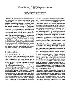
Figure 1. Network model
application completely finishes, that is, until SRUs from all connections are received by the client (such application is called a barrier synchronized application). For this reason, once a timeout occurs, a long idle period appears in the client link, and consequently the average throughput over the period between the starting time of the sendings of the request from the client to the servers and the finishing time of the receiving of all the SRUs is small.
4. AVOIDANCE OF TCP INCAST 4.1. Network Model When we focus on the Incast problem, we can simplify data center networks to a network model shown in Fig. 1. There are one client and several servers. The client and the servers are connected to one Ethernet switch. A port buffer is equipped in the client link, and some packets can be temporarily buffered when the link is busy. We can consider a network model where there are some switches and some servers and the client are connected to different switches. However, as long as the client link is a bottleneck, such model can be simplified to the model shown in Fig. 1. For the simplicity of the discussion, we assume that each link bandwidth is equal to each other and denote the bandwidth by V [Gbps], and we define BaseRTT between the client and a server as the round trip time of one packet with MSS [Byte] under the condition that there is no other traffic. We also assume Base RTT between the client and each server is equal to each other (note that we can easily obtain Base RTT by a prior experiment for a target data center network).
4.2. Complete Connection Serialization As described in the previous section, the cause of Incast is that transmissions from many servers to the client simultaneously occur. In a barrier synchronized application, the SRU receive finish time in each connection is not so important but the all SRU receive finish time, that is, the time when all SRUs are received by the client is very important. Therefore we do not have to use parallel SRU transmissions which have the high possibility of Incast occurrence. Based on the consideration described above, we serialize establishments of all the connections belonging to each application as shown in Fig.2. In the figure, we assume that there is one client requesting three servers to send SRUs. The client first establishes one connection (con-1) for a server of the three servers and receives the SRU from the corresponding server. Then, the client repeats the same behaviour for the second (con-2) and third (con-3) connections serially.
86
International Journal of Computer Networks & Communications (IJCNC) Vol.8, No.4, July 2016
In this serialization, we establish only one TCP connection belonging to a barrier synchronized application. On the other hand, we allow any TCP connection which does not belong to such application to be established and there may be some traffic from UDP, ICMP, routing protocol and so on. However, the total amount of such traffic (we call it background traffic) can be considered to be very small compared to the traffic from barrier synchronized applications because background traffic is used for system control and management (in other words, we should avoid such system design that generates large amount of control and management traffic). Therefore, we can consider that packet losses. Due to Buffer overflow At The Port buffer Hardly occur.
Figure 2. Complete connection serialization
Thus, we can nearly perfectly avoid Incast using the serialization. We call such serialization complete connection serialization (hereafter CCS briefly). As described above, we can consider that packet losses due to buffer overflow at the port buffer hardly occur. On the other hand, because data center networks have high quality transmission devices and lines, we can consider that bit errors hardly occur, and consequently packet losses due to bit errors also hardly occur. Even if such packet loss occurs, such packet loss can be recovered by three duplication ACKs (fast retransmission and fast recovery mechanisms) and consequently Incast can be avoided. Therefore, hereafter, we can assume that packet losses due to buffer overflow at the port buffer do not occur in CCS method and packet losses due to bit errors do not occur in CCS method and others methods including normal TCP. 87
International Journal of Computer Networks & Communications (IJCNC) Vol.8, No.4, July 2016
In each connection, the client advertises BaseBDP [Byte] as its receive window size to the corresponding server where BaseBDP = V/8 × BaseRTT. In a typical data center network, because V is 1 Gbps (109 bps) and BaseRTT is about 100 µsec, BaseBDP is about 12500 Bytes (1 × 10⁹/8 × 100 × 10-6). Since the client advertises BaseBDP as its receive window size, the send window size (sendwin) of each server is as follows:
Figure 3. Timing chart in client-server communication
=
, BaseBDP ,
(1)
Where cwnd is the congestion window size of the server. Therefore in each connection, sendwin increases exponentially in the initial stage due to the slow start mechanism of TCP, and then it reaches BaseBDP as shown in Fig. 2(a) to (c). The length (T1) of the initial stage depends on V, BaseRTT and MSS, and it is derived as follows. We assume that the client starts connection establishment (the client sends a SYN segment) as shown in Fig. 3 and the initial cwnd value is 2 × MSS (We denote cwnd normalized by MSS by cwnd_pkt. Thus, the initial cwnd_pkt is two), and we also assume that the time origin is the time when the server returns a SYN-ACK segment. Then, T1 is given as follows:
BaseBDP_pkt
('
=
BaseBDP MSS +
= !"#$% BaseBDP_pkt& + ' =
− ' × BaseRTT MSS + +,!BaseBDP_pkt& − % -% . × 0
(2)
(3)
×/
(4)
BaseBDP_pkt is the value of BaseBDP normalized by the maximum size packet. The value of “40” in Eq.(2) isthe total number of bytes of the fixed parts of IP and TCP headers. m is the number of BaseRTTs which are necessary for cwnd_pkt to exceed BaseBDP_pkt. Because cwnd_pkt doubles per BaseRTT, m is expressed by Eq.(3).Because the number of packets sent 88
International Journal of Computer Networks & Communications (IJCNC) Vol.8, No.4, July 2016
from the server during the i-thBaseRTT is 0 (i = 1) or 2i−1 (i≥ 2), cwnd_pkt is equal to 2m−2 at the start of the (m−1)st BaseRTT. Thus, when the server receives ACKs whose number is equal to!BaseBDP_pkt&−2m−2, cwnd_pkt reaches !BaseBDP_pkt& during the m-th BaseRTT. Thus, T1 is calculated by Eq.(4). Figure 3 is an example case of BaseBDP_pkt = 6.5. Then m = 4 and !BaseBDP_pkt&−2m−2= 7−4 = 3. Therefore as shown in Fig.3, the endpoint of interval T1 is identical to the time when the server receives the third ACKs from the client in the fourth BaseRTT.
The length (T2) of the period between the time when sendwin reaches BaseBDP and the time when the connection finishes depends on V, BaseRTT, MSS and SRU size S and is calculated as follows: -' -' 3 − ∑ 5% % × MSS MSS + (% = 2 6× MSS 0
×/
(5)
For example, when V = 1 Gbps, BaseRTT = 100 µsec, MSS = 1460 Bytes and S = 64 KBytes, T1 = 412 µsec andT2≃ 360 µsec. If SRU size is too small, a connection finishes before its sendwin reaches BaseBDP so that T1 and T2 are not defined. Specifically if and only if the following inequality is not satisfied, T1 and T2 are not defined.
8
-%
3 9 − : % -' + % MSS 5%
-%
≥ !BaseBDP_pkt&
(6)
The first term of Eq. (6) is the number of packets generated from the SRU, and the second term is the total number of packets sent from the second BaseRTT to the (m-2)nd BaseRTT. Thus, the difference between the two terms means the number of remaining packets which have not been sent yet at the start time of the (m-1)st BaseRTT, and if the server sends each of the remaining packets during the (m-1)stBaseRTT, the server can receive one ACK during them-thBaseRTT. On the other hand, cwnd_pkt is 2m−2at the start time of the m-thBaseRTT. Therefore, the lefthandexpression means cwnd_pkt after all the packets belonging to the SRU. Thus, if Eq.(6) is satisfied, cwnd_pkt exceeds!BaseBDP_pkt& and consequently T1 is defined, and therefore T2 is also defined.
When BaseBDP_pkt = 6.5 and m = 4 as described above, if !T3’and the second and the third periods T1 appear only CCS method. Thus, comparing Figs.2(e) and 4(e), we can see that throughput in CCS method in each of periods T1 is smaller than that of simultaneous transmission and consequently finish time 3(T1 + T2) in CCS method is larger than finish time T3’ + T4’in the simultaneous transmission.
4.3. Nearly Complete Serialization As described in the previous section, CCS method has periods T1 in which the bandwidth of the client link cannot be fully utilized, and consequently the finish time of an application is larger and the average throughput is smaller than the simultaneous transmission. In order to reduce the underutilized periods as much as possible, we consider a strategy which overlaps two connections partially as shown in Fig.5. In the strategy, the client tries to establish the next connection at a time (time t1 in the figure) in advance so that sendwin of the connection reaches BaseBDP at the time (time t2 in the figure) when the current established connection finishes. It is hard to derive time t1 correctly because the two connections share the bandwidth of the client link. We determine time t1 approximately as follow. 91
International Journal of Computer Networks & Communications (IJCNC) Vol.8, No.4, July 2016
Figure 6. Overlap of more than two connections
For the simplification of the description, we call the current connection and the next connection con-A and con-B, respectively. If we assume that only con-B exists in the network, sendwin of con-B can reach BaseBDP after the period of length T1 in Eq. (4). However, con-A and con-B coexist in the network. Thus, we assume that two connections equally share the bandwidth of the client link and we consider that 2T1 is needed for sendwin of con-B to reach BaseBDP. Also from the equal sharing assumption, we consider that con-A can use half the bandwidth (V/2) of the client link averagely. Therefore con-A can send the data of T1V(2T1×V/2) [bit] during the period between t1 andt2. Hence, we can obtain time t1 as the time when the number of bits which have been already sent in con-A reaches S − T1V (Recall that S means the SRU size). From the above discussion, the client counts up the number of bits which has been already sent in the current connection, and when the number reaches S − T1V, the client starts the next connection (we call the condition that he number of bits in the current connection reaches S − T1Vthe condition-I). However, because S − T1V is an approximate value, if the client starts the next connection based on condition-I only, the situation that there coexists more than two connections may occur. For example, in Fig.6, assume that because the condition-I is satisfied for connection con-A, the client starts connection con-B at time tb. Then if the condition-I is satisfied for con-B at time tc, a new connection con-C starts. But at time tc, con-A may have not finished yet and remains alive. Such situation is easier to occur when S is smaller. If we allow such multiple overlapping without any restriction, Incast may have occurred. Thus, we introduce the overlapping parameter K and we do not allow establishment of a new connection belonging to the same barrier synchronized application when the number of already established connections is K, and when one of them finishes, we allow the client to establish a new connection. We call such connection serialization nearly complete connection serialization (hereafter NCCS briefly).
4.4. Optimized Connection Serialization In NCCS method, the client starts the next connection when the number of bits which exceeds S − T1V. Thus, when the inequality (6) is not satisfied because the SRU size is too small to define T1, we cannot use the method. In order to resolve these problems described above, we adopt a strategy which considers a set of several connections as one connection and serializes such sets like NCCS method as illustrated in Fig. 7. In the figure, the client establishes the set of three connections (con-1, con-2 and con-3) simultaneously. Then, the client starts the next connection when the number of bits which exceeds S − nT1×V/n, where n means the number of connections in each set.As described later, n is selected so that each set can fully utilize the client link’s bandwidth.
92
International Journal of Computer Networks & Communications (IJCNC) Vol.8, No.4, July 2016
Figure 7. Optimized connection serialization
In the strategy, the number of bits queued in the client link buffer becomes at most three BaseBDPs as described later. Hence, even with such a small buffer size, we can fully utilize the client link’s bandwidth without causing Incast. We call such serialization optimized connection serialization (hereafter OCS briefly). In NCCS method, the period needed for sendwin of the next connection to reach BaseBDP is assumed to be 2T1.Therefore if T2 ≥ 2T1, we can fully use the client link’s bandwidth by overlapping at most two connections. From Eqs.(4) and (5), the inequality T2≥ 2T1 is expressed as follows: 3 ≥ % × BaseBDP_pkt × !"#$% BaseBDP_pkt& 8 9 (7) MSS +% × !BaseBDP_pkt& − %
When the SRU size (S) satisfies the inequality, we simply use NCCS method, that is, we consider a set consists ofone connection as the set described above. On the other hand, when the SRU size does not satisfy the inequality, weconsider each set of n connections as one connection in NCCS method and define T1 and T2 of each set in the sameway. Then, if T2≥ 2T1 is satisfied, we can fully use the client link’s bandwidth by overlapping at most two sets. Theinequality T2≥ 2T1 is described as follows: ×8
3 9 MSS
≥ % × BaseBDP_pkt × !"#$% BaseBDP_pkt&
+% × !BaseBDP_pkt& − %
(8)
By the above inequality, we select the minimum value (nmin) of n satisfying it to decrease the queue length of the client link buffer as much as possible (It is trivial that if inequality (7) holds, inequality (8) holds for n = 1. Therefore, when we simply use NCCS method with the set of one connection since inequality (7) holds, we consider nmin= 1). If the client advertises !BaseBDP_pkt⁄>?@A & as the send window size (say wnd_pkt) of each server, we can fully usethe client link bandwidth. However, when BaseBDP_pkt⁄>?@A is smaller than four and if one packet loss occurs, thefast retransmission and fast recovery mechanisms are not triggered because three duplicated ACKs are not returned toeach server due to a small send window size. As a result, for retransmissions of the lost packet, we should wait theretransmission timeout and consequently Incast may occur. Therefore, when BaseBDP_pkt⁄>?@A is smaller than four,we set wnd_pkt to four. Thus, wnd_pkt is set as follows. 93
International Journal of Computer Networks & Communications (IJCNC) Vol.8, No.4, July 2016
BCD
=E
8
BaseBDP_pkt 9, ,
BaseBDP_pkt⁄ BaseBDP_pkt⁄
≥
?@A , we can not fully utilize the client link’sbandwidth. For the purpose of performance improvement, when the number of remaining connections is smaller than nmin, the client increases the advertised window sizes of remaining connections so that the sum of sendwins becomes BaseBDP to fully use the bandwidth. Next we describe the timings of three-way handshakes. As shown in Fig.7, if the client executes three-way handshakes during the overlap period of cons-1 ∼ 3 and cons-4 ∼ 6, the probability that the SYN-ACK packets fromservers of cons-4 ∼ 6 are lost may be high because the number of packets in the port buffer of the client link may be large due to packet transmissions of cons-1 ∼ 3. In normal TCP implementation, when a SYN-ACK packet is lost, there transmission timeout is three seconds and consequently throughput becomes much lower. Thus, the client executes threeway handshakes as described in Fig.8. Three-way handshakes in each connection set are performed in the initial duration where packet transmission rates is not high, and the client advertises receive windows of size 0 to every set except the first set to avoid data transmission of every set except the first set. After that, the client advertises non-zero windows to the i-th set (i> 1) when the (i-1)st set connections transmit data of S − nT1×V/n [bit]. NOP The maximum number (K?LM ) of TCP packets in the port buffer is calculated as follows. Because the number of packets sent from each server iswnd_pkt and the maximum number of connections is 2 × nmin for the overlap period, the maximum number of packets in the network is 2 ×nmin ×wnd_pkt. On the other hand, from the definition of the bandwidth-delay product, the network can accommodate BaseBDP_pkt packets without using the client link port buffer. NOP Therefore, if we assume that the buffer capacity is sufficiently large, we can calculate K?LM as follows:
94
International Journal of Computer Networks & Communications (IJCNC) Vol.8, No.4, July 2016
R(UV ST = % ×
×
_BCD − BaseBDP_pkt
(11)
NOP We show K?LM becomes at most three BaseBDP_pkts in Appendix A.
5. PERFORMANCE EVALUATION 5.1. Effectiveness of serialization methods Table 1. Simulation parameters
Parameter BaseRTT (µsec) Bandwidth V (Gbps) Port buffer size (packets) SRU size S (KBytes) The number of the servers (NS ) The number of active servers RTOmin (msec) UDP background traffic ratio x (%)
Value 100 1, 10 40, 120, 200 32, 64, 128, 256, 512, 1024 64, 256, 1024 1 ~NS 200, 0.2 (fine-grained timer) 0, 0.1, 1, 10
We incorporated the proposed methods into the NS2 simulator [30] and performed extensive simulation runs. In the simulations, we assume that there are no bit errors in packets. We use the network model as shown in Fig.1, which has one switch, and one client and all servers are connected to the switch. Table 1 shows the values of simulation parameters. An active server means a server which has an SRU of a requested block. That is, for example, when SRU size is 32 KBytes and the number of active servers is 20, we randomly select 20 servers from NS servers and we assume that the client requests transmission of the SRU of size 32KBytes to each of the 20 servers (that is, the requested block is 32 KBytes× 20). RTOmin means the minimum timeout value in TCP and we set RTOmin in the method with a fine-grained timer (we call the method TCPFG method) to 0.2msec (200 µsec) and set RTOmin in the other methods to 200 msec (default value in normal TCP). In our simulations, we used UDP traffic as background traffic and assume that when its ratio is x% and the bandwidth is VGbps, each server generates UDP traffic with the constant bit rate of V×x/100 × 1/NS. Fig.9 shows the goodputs when NS = 64, V = 1 Gbps, S = 32 KBytes, x = 0.1 % and the port buffer size is 40packets, where goodput is the value of throughput (application level throughput) when the sum (40 Bytes) of TCP andIP headers are not included in throughput calculation. The goodputs are the average goodputs over 20 simulation runs with the same parameters. We also set such simulation parameters that MSS is 1460 Bytes, MTU is 1500 Bytes and overhead of layer 2 or lower is zero. Thus, the maximum goodput, which is defined the goodput when we fully use the client link bandwidth, is about 972 Mbps (= 1 Gbps − 1 Gbps×0.1/100 × 1460/1500). Fig.10 shows the maximum number (Qmax) of all TCP and UDP packets in the client link port buffer in each method. In the both figures, legend "NTCP" means normal TCP implementation without any Incast avoidance mechanism.
95
International Journal of Computer Networks & Communications (IJCNC) Vol.8, No.4, July 2016
Drastic goodput degradations occur in NTCP and ICTCP when the number of active servers is over about 15in Fig.9 because Qmax is easy to reach the buffer capacity of 40 packets as shown in Fig.10. Although ICTCP decreases the send window size of each connection to avoid Incast, its minimum value is 2 × MSS. Thus, whenthe number of active servers is larger than about 20 (the port buffer size of 40 packets / the minimum send window size of 2 × MSS), Incast can occur with high probability. In Fig.9, however, we can observe that goodput degradations in ICTCP occur when the number of active servers is over about 15 (not over 20). This reason is because ICTCP does not always set the send window size of each connection to the minimum value and sometimes set to more than 2 × MSS. Therefore, goodput degradations may occur in ICTCP even when the number of active servers is smaller than 20. As expected, although CCS method attains the smallest Qmax as shown in Fig.10, it cannot fully use the client link bandwidth and its goodput is about 450 Mbps as shown in Fig.9. Fig.10 shows Qmax in CCS method is not constantly equal to 0 because there are some background traffic. Therefore, when CCS method is used, the switch should have a few buffer for a background traffic. By using NCCS method with K = 4 instead of NCCS method withK = 2, we can almost fully use the client link bandwidth although Qmax becomes larger than NCCS method with K =2. For the parameter setting to obtain Fig.9, even if we use larger value of K, Incast did not occur in our simulation runs. However, generally speaking, if we use larger value of K, Incast can occur as shown later (see Fig.13).Therefore, in order to fully use the client link bandwidth using NCCS method, although we have to use optimal valueof K, we do not obtain any methods to optimize K at present. On the other hand, OCS method also almost fully uses the client link bandwidth and attains slightly larger goodput than NCCS method with K = 4 while limiting smaller number of packets in the port buffer. From Eqs.(2), (9), (10) and (11), BaseBDP_pkt = NOP !1Gbps × 100μsec/ 1500 × 8 &= 9,wnd_pkt = 4, nmin = 3 and K?LM = 8 × 3 − 9 = 15. On the 96
International Journal of Computer Networks & Communications (IJCNC) Vol.8, No.4, July 2016
97
International Journal of Computer Networks & Communications (IJCNC) Vol.8, No.4, July 2016
other hand, the simulation results of Fig.10 show Qmax of OCS method is about 13. Because UDP NOP traffic is very small (a × b/100 × 1/cd × cd = 1Gbps×0.1/100×1/64×64 =10Mbps), K?LM and Qmax are close values. In TCPFG, since Qmax reaches the port buffer size as shown in Fig.10, Incast (timeout) frequently occurs. However, such smaller retransmission timeout value contributes to keep goodputs high as shown in Fig.9. However, when the number of active servers is large (values larger than about 40 in Fig.9), goodput degradation occurs because timeout excessively occurs in a short span, although the degradation is smaller than NTCP and ICTCP. Figs.11 and 12 show mission complete time (MCT) which is the period between the time when the client sends thefirst SYN segment to a server and the time when the client finishes receiving all packets belonging the same barrier synchronized application. The ideal MCT under the condition that the client can fully use bandwidth becomes as follows: Figs.13, 14, 15 and 16 show goodputs, Qmaxand MCT (in logarithm and linear scales), respectively, whenNS = 256, V = 10 Gbps, S = 512 KBytes, x = 0.1 % and the port buffer size is 200 packets. In NCCS method with K = 8, as suggested before, Incast occurs due to setting large value of K. Hence, goodputs of NCCS methodwith K = 8 becomes less than NTCP. Fig.13 shows NOP that OCS method has the best goodputs. In OCS method,K?LM = 84 (= 2 × 4 × 21 − 84) which is derived from Eq.(11) where BaseBDP_pkt = 84, nmin = 4 and wnd_pkt = 21.On the other hand, the simulation results show Qmax = 90. In the parameter settings, UDP traffic is a little bit large(10Gbps × 0.1/100 × 1/1024 × 1024 = 100Mbps). Therefore Qmax is a little bit larger NOP thanK?LM . From the above discussion, we can conclude that OCS method is the best Incast avoidance method. efg = hS × 8
3 MSS + 9× MSS 0
( 12 )
Where Na is the number of active servers. For example, when S = 32 KB, V = 1 Gbps and Na = 8, MCT becomes 2.2msec. Note that above MCT does not include computing time for transmitting and propagation delay since they are negligibly small, and we assume that the client can fully use bandwidth without restrict of TCP window controls. As shown in Figs.11 and 12, MCT in NCCS (K = 4 and K = 8) and OCS methods are almost equal to the ideal MCT.
5.2. Investigation on TCPFG’s Performance Degradations As described above, TCPFG with RTOmin = 0.2 msec suffers goodput degradations when the number of servers is large. In order to investigate the reason, we executed simulation runs with the values of RTOmin as200, 10, 5, 1 and 0.2 msec, respectively. The other parameters and network model in the simulation runs are the same as the previous section. Figs.17 and 18 show goodputs and the number of retransmission timeouts per connection, respectively, where NS = 256, V = 10Gbps, S = 512KBytes, x = 0.1 % and the port buffer size is 40 packets. When the number of servers is large, we can observe that goodputs degrade as shown in Fig.17 and also observe that the number of retransmission timeouts increases as shown in Fig.18. The reason why goodputs degrade is that the server repeats retransmission timeouts due to heavy congestion. As long as a retransmitted packet is not acknowledged, the server repeats the retransmission with setting retransmission timer with doubled value ofRTO per retransmission. 98
International Journal of Computer Networks & Communications (IJCNC) Vol.8, No.4, July 2016
Therefore, too many retransmission timeouts lead to a large RTO which doesnot recover packet losses in proper time and stop sending data for a long period, and consequently their goodputs become low. In general, we have to find the optimal timeout value to keep high goodputs in TCPFG. The goodputs of RTOmin = 1 msec is clearly greater than that of RTOmin = 0.2 msec as shown in Fig.21. This indicates the best RTOmin is not the smallest one. Therefore, in TCPFG, we should carefully decide the value of RTOmin depending on network environments.
6. DISCUSSION In our methods, a client TCP needs to know which connections belong to a barrier synchronized application. One method to know that is that the application informs TCP of connection information if we are allowed to modify the application. If not, we can infer such connections by considering that all the connections which almost simultaneously request TCP to be established belong to the same application. In NCCS and OCS methods, the client TCP needs to know SRU size. One method to know the size is that the application informs TCP of the size if we are allowed to modify the application. If not, we can learn the size by observing the first connection because SRU sizes of all the connections belonging to the same application are the same, and we can apply the methods to the other connections. Thus the implementations of our methods are not so hard. In Section 3, we assumed that each link bandwidth is equal to each other and BaseRTT between each client and each server is equal to each other. Then, we discuss Incast avoidance when the assumptions are not satisfied. Our proposed methods try to fully utilize the client link bandwidth. Therefore if the client link bandwidth is larger than bandwidths of server links, throughput of our proposed methods can be smaller than the conventional methods because our methods limit the number of simultaneously established connections and consequently throughput is bounded by server link bandwidths. As a method to deal with such case, we can consider the following method which is a minor change version of OCS method. The method directly uses OCS method with the minimum timeout of a few hundred micro seconds by using a fine-grained timer proposed in [24]. After the client establishes connections, it performs online measurement of throughput value in client TCP, and if the value is much smaller than the client link bandwidth, then we additionally establish some connections, and we repeat such procedures. We will develop the method as one of our future work. Regarding the difference of BaseRTT values, the difference can be considered small in normal data center networks. Therefore, we should use the maximum value among RTT values to maximize throughput.
7. CONCLUSIONS We have proposed three connection serialization methods to avoid TCP Incast, and we have shown their effectiveness. Our future work is to refine and evaluate the method described in Section 5 to deal with a case when bandwidths of the client link and server links are different.
APPENDIX BUFFER
A. THE
MAXIMUM NUMBER OF
TCP
PACKETS IN THE PORT
NOP The maximum number (K?LM ) of TCP packets in the port buffer connected the client link is derived as follows.
(1) In the case of (a) in Eq.(9), 99
International Journal of Computer Networks & Communications (IJCNC) Vol.8, No.4, July 2016
=%×
R(UV ST
×
_BCD − iFjkilm_nop BaseBDP_pkt ×8 9 − iFjkilm_nop
=%×
(1-1) If we assume that BaseBDP_pkt = k∙nmin + r (k is an integer number and 0 ?@A ,
(A. 1)
9 − iFjkilm_nop
(A. 5)
(A. 6)
(2-1) If we assume that BaseBDP_pkt = 4w + r (k is an integer number and 0