T&D-Bench+ - A Software Environment for Modeling and Simulation of State-of-the-Art Processors Sandro Neves Soares1 Universidade de Caxias do Sul Caxias do Sul, Brazil
[email protected]
Flávio Rech Wagner Universidade Federal do Rio Grande do Sul Porto Alegre, Brazil
[email protected]
1. Introduction Environments for modeling and simulation of state-ofthe-art processors can be classified into two categories: design and teaching environments. While the former have powerful modeling resources, the latter put emphasis on tracking and steering experiments at simulation time. Design environments are based on dedicated modeling languages and offer development tools that allow the detailed description of any computational system. Special skills are required from the designers to use the tools and the language in order to create new processor models. This is not a trivial task since the specifications are very detailed. Consequently, the time to achieve a complete and correct description of a processor is considerable. Modeling languages used in design environments can be either hardware description languages (HDLs) or architecture description languages (ADLs). HDLs model mainly the processor organization, and the descriptions are very detailed to allow synthesis or rapid prototyping in FPGAs. ADLs, in turn, model both architecture and organization, but the descriptions are more abstract and rapid prototyping is usually not possible. Teaching environments are simulators developed to help the students make the connection between their theoretical knowledge and the practical experience. They offer specialized facilities for interaction with the model at simulation time, for visualization of results and modification of some aspects of the model, either state values or functionality. Modeling facilities in teaching environments are primitive when compared to those in design environments, since the allowed model modifications are very simple, but resources for user interaction with the model are much more powerful. This paper presents T&D-Bench+ (Teaching and Design Workbench), an environment for modeling and simulation of state-of-the-art processors, including RISC and VLIW processors, DSPs, and microcontrollers.
1
Phd student at PPGC-UFRGS
T&D-Bench+ has the modeling flexibility of design environments, considering both processor organization and architecture, allows descriptions that are sufficiently detailed to be used in rapid prototyping, and has all the required facilities for interaction as in teaching environments. But T&D-Bench+ does not only combine the advantages of design and teaching environments. Additionally, it includes features that are not usually found in both types of environments. Processor models are specified at a higher level of abstraction, and are thus more intuitive to the designer, and can be generated almost entirely in a visual and interactive way. Programming, although necessary to complement the visual models, is based on a general purpose and objectoriented language and benefit from specialized directives that greatly help the modeling process. Simulation code generation is done automatically by the environment. The remaining of this paper is organized as follows. Section 2 discusses related work. Section 3 describes the T&D-Bench+ design methodology and its modeling environment, while Section 4 briefly introduces the execution environment. Section 5 evaluates T&D-Bench+ as compared to HDLs and ADLs. Final conclusions are drawn in Section 6. 2. Related Work Languages for design environments fall in two main classes: hardware description languages (HDLs) and architecture description languages (ADLs). Both of them can be used to model a vast variety of processors, but their flexibility make it very hard to model a complex processor. The use of languages to describe computational systems shows some drawbacks: textual descriptions are tedious and non-intuitive, and the length and repetitive nature of these descriptions increase the possibility of errors. Additionally, the user must develop skills using a dedicated language and all related tools.
The main objective of HDLs, as VHDL and Verilog, is the development of hardware. They model the processor organization and do not have dedicated facilities to model the processor architecture. On other side, the detailed hardware descriptions permit rapid prototyping in fieldprogrammable logic devices. ADLs, as LISA [1] and EXPRESSION [2], are used to rapidly explore and evaluate design alternatives for processors and their memory systems, to be used usually in embedded systems-on-chip. They automatically generate retargetable tools for experimenting with the designed processor, such as simulators, compilers and debuggers. Some ADLs, in opposition to HDLs, model the organization as well as the architecture of processors. But the more abstract nature of the descriptions, whose only objective is to generate the retargetable tools, is not indicated to synthesis or rapid prototyping. Teaching environments are simulators developed to teach computer organization and architecture. They have graphical interfaces with various (but fixed) resources for user interaction, but are usually restricted to a single processor. The processor model has a flexible on-line configuration, so that the user may for instance choose among pipelined and non-pipelined versions, set and reset a forwarding mechanism, and set cache and I/O parameters. SATSim [3], DLXview [4] and SPIECS [5] are good examples. The HASE [6] simulator is more generic since it permits the creation of new simulation models. Some simulators, such as SimpleScalar [7] and RSIM [8], are large and complex programs, mainly oriented to research activities, that describe in detail a computational system and have been later introduced in the educational environment. SimpleScalar shows a very large number of parameters for processor and cache configuration, but does not offer interaction resources. The simulator offers the Alpha, PISA, ARM, and x86 instruction sets. It is open source, so that the user may modify any aspect of the processor model, but this must be done by modifying a C program that details the processor simulation. 3. Design Methodology The following requirements were specified for the modeling process in the T&D-Bench+ environment, based on the drawbacks of current design and teaching environments: - use of visual interactive modeling (VIM) resources and object-oriented related concepts to facilitate and acelerate the process of modeling state-of-the-art processors. A VIM environment [9] provides resources for a visual and interactive construction of the models; - availability of resources to model the organization as well as the architecture of processors; and
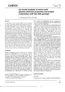
- the processor organization must include enough details to be used as input description for a synthesis or rapid prototyping process. The T&D-Bench+ design methodology is implemented by a modeling environment composed by a class library and a modeling tool (Figure 1). By means of the modeling tool, the designer creates new simulation models of stateof-the-art processors using classes available in the class library. The models are then simulated in the T&DBench+ execution environment. Class Library
Modeling Environment Bus
Datapath
Modeling Tool
Processor Memory
Register
InstructionType PipeStage
Execution Environment
Server
Master Client
Processor Model Client Client
Figure 1. General view of T&D-Bench+
3.1 Class Library The class library is a repository of classes to be used in the development of processor models. Classes can be of three distinct types: functional classes, control classes, and visualization classes. This paper will detail only functional and control classes. The use of these classes can be made in a direct or indirect way. The direct use of a class means the possibility of altering its behavior by providing specializations and modifications in its source code. The indirect use involves only the generation of the data necessary for the class at execution time, without acess to the class source code. The former are called external classes and the latter are called internal classes. 3.1.1 Functional classes. The functional classes correspond to the different structural components in the processor functional block (or datapath), such as multiplexers, registers, logic and arithmetic units, register files, memories, and others. The class library contains a large variety of classes representing structural components found in state-of-theart processor datapaths. But the programming of new classes is also possible, starting from scratch or by specialization of other available non-abstract classes,
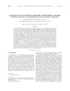
using the facilities of the object-oriented Java language. New classes must inherit the characteristics from one of two basic classes: combinational or sequential. Both are derived from the basic class circuit. These basic classes are abstract. They serve as templates indicating the methods to be provided by the designer, for example. A typical functional class is composed by three types of ports: input ports, output ports, and control ports. Functional classes describing sequential circuits have, additionally, a component to save the attribute values in the circuit, called contents. NR1
NR2 S1
registers
E1
S2 NW1
Figure 2. Functional class Register File Figure 2 shows the representation of a functional class describing a register file, which can simultaneously read from two registers and write to a third register. The class has one input port that provides the value to be written into one of the registers, two output ports carrying the values read from two registers, and three control ports, NR1, NR2 e NW1. They specify the addresses of the two registers to be read and the address of the register to be written. The values in the component contents of the class correspond to the contents of each register. Besides ports and contents, functional classes also have attributes and behavior. Attributes are used to store values that define a specific instance of a class, such as the number of registers in a register file, for example, or carry status information, such as a flag to indicate that a new instruction was just fetched from the instruction memory. Their values are defined in the object instantiation or by the control classes. The behavior is defined by one or more methods that correspond to the functionality of the datapath structure being described. Usually, they operate on the input data and generate and save results. According to the type of component for which the designer is developing a functional class, there are specific methods whose code must be provided. The method behavior must be provided for combinational circuits. For sequential circuits, the required methods are read and write. Figure 3 shows the Java code for read and write methods of a functional class describing a memory with two input ports (data and address) and one output port.
// write method: read the inputs, data E1 and address E2 // assign E1 to the contents position whose address is E2
public void write ( ) { int iE1t, iE2t; iE1t = inE1.get ( ); iE2t = inE2.get ( ); CContents.set ( iE1t, iE2t);
}
// read method: read input E2, address, fetch its content // send the read value to the output S1 and, if the bus // is connected, activate it to send the value forward
public void read ( ) { int iE2t, iS1t; iE2t = inE2.get ( ); iS1t = cContents.get ( iE2t); outS1.set ( iS1t); if ( busBs1.isLinked ( ) == true) busBs1.behavior ( ); }
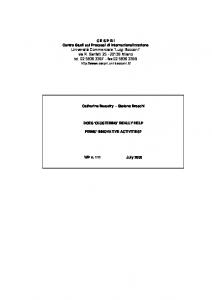
Figure 3. Methods Write and read The class bus is distinct from other functional classes. The function of a bus is to propagate data between two instances of functional classes describing datapath components of the processor (source and target). pc
S1
imemory
E2
Figure 4. Bus connecting pc and imemory A bus instance named pc_S1:imemory_E2 connecting the output of the register pc to the address input of the instruction memory imemory (see Figure 4) is described, as any other bus, by the identification of the instances of functional classes and their respective input and output ports to be connected (functional classes may have more than one input or output port. The imemory, for example, contains two input ports: data and address). Additionally, the functional class bus has a method that is responsible for sending the value in the output port of the source component to the input port of the target component. This method is executed always after the source component has its behavioral method executed during simulation. The class datapath is used to aggregate the instances of functional classes of the processor (components and busses). There is only one instance of the class datapath during simulation, which is used to communicate with the processor control block, described in the next section. The use of the class datapath is transparent to the designer, so that its source code cannot be altered. Only its contents, containing components and busses, can be defined by the user. This means that the class datapath is an internal class, while classes corresponding to components and busses are external ones. 3.1.2 Control classes. The control classes correspond to the control block of the processor. They define what is
executed by the components in the datapath instance during simulation. They can be of three distinct types: processor, p i p e s t a g e , and instructiontype. The class processor is external, while the other control classes are internal. The class pipestage has as many instances, during simulation, as the number of pipeline stages in the processor. It is composed by an attribute name and by a reference to the instruction that is being executed in the stage at a given time. The class instructiontype has as many instances as the number of instruction types of the processor. Instructions of a given type activate (or execute the behavioral methods of) the same datapath components and differ only by the numeric values provided to certain control ports of these components. The difference between instructions ADD and SUB, for instance, both of the type integer arithmetic, may be only the operation code to be provided to the ALU. The class instructiontype is composed by the attribute name and by a linked list called functionality list, where each node contains a reference to a component to be activated or to a control port to be configured. The information in this list describes the instruction type function and is generated by the modeling tool. An instance of a instruction that is being executed makes a copy of the functionality list that corresponds to its type and modifies what is necessary, according to the code provided by the designer in method decode of the class processor, to be discussed later. The value concerning the operation code to be provided to the ALU, for instance, can be modified to indicate a instruction SUB. During the execution of an instruction, each node of its functionality list becomes a message to the object datapath, indicating the activation of a component or the configuration of a control port. The class processor is composed by one instance of the class datapath, one or more instances of the class p i p e s t a g e , and several instances of the class instructiontype. These three classes are internal and have their specifications created by the modeling tool. The class processor can also have attributes such as name and frequency. The class processor also has several methods. Some must be customized, as the method behavior. Other methods must be generated from scratch, as fetch and decode. And others, as execute, have a predefined behavior. Additional methods can be created according to the designer needs. The methods execute and behavior build the functional kernel of the processor. The method execute is invoked at each simulation time unit, which can be equal to a clock cycle, to execute the instructions in the different pipeline stages. An instruction execution, at each time step,
considers only the part of its functionality that is relative to the pipeline stage that is being executed. The method behavior is invoked always after execute. It invokes the methods fetch and decode that must be provided by the designer. The former must return an instruction code. And the latter must interpret this code to create an instance of instruction. It must identify the instruction type and copy the corresponding functionality list with the necessary modifications. The instruction is then inserted in the first pipeline stage. The method behavior is also responsible for advancing instructions through the pipeline stages. The increment of the simulation time is also performed in this method and can be programmed by the designer in various ways. The most common way is the increment each time the method is invoked. If the designer creates additional methods for the class processor, they must be invoked in the method behavior. The source code of the class processor is developed in Java in the modeling tool. In the future we intend to generate most part of this code automatically.
3.2 Modeling Tool A software environment that includes VIM (visual interactive modeling) resources is used by the designer to develop processor simulation models based on the design methodology described in the previous section. Tools in this environment give the designer support for assembling the processor datapath and defining its control block functionality. The available tools are: 1 . a graphical editor for assembling the processor datapath and for defining its pipeline and types of instructions; 2. a text editor for customization of the class processor; and 3. a tool for the syntactic verification of the code of the class processor. The definition of the processor datapath is performed in the graphical editor by the selection, positioning, and connection of graphical representations of instances of the functional classes available in the class library. Additionally, this editor supports an interactive definition of the instruction types, by pointing at the components in the graphical datapath representation. For each instruction type, the user interactively selects a sequence of components that must be executed. For each component, the user must also choose the method of this class to be invoked when an instance of that type of instruction is being executed (behavior, read or write methods). The Java source codes for the classes datapath and instructiontype are then automatically generated by the modeling tool.
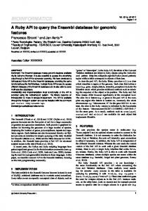
The next sections show the modeling of the DLX processor [10], to illustrate the modeling tool functionality. 10
1
11
12
13
7
2
8 3 9 4
5
6
Legend: 1. ADD 5.REGISTERS 9. MUXWB 13. MEM/WB
2. MUXPC 6. MUXA 10. IF/ID
3.PC 7. MUXB 11. ID/EX
4.IMEMORY 8. ALU 12. EX/MEM
Figure 5. DLX datapath 3.2.1 Datapath definition. The datapath definition is interactively performed with the graphical editor as described before. Figure 5 shows the DLX datapath as it is drawn by the designer. The information in Figure 6 is then automatically generated by the environment. It will be used in the datapath object composition during simulation execution. // Create the datapath components create pc REGISTER create imemory INST_MEMORY 4 create add ADDER 1 create muxpc MULTIPLEXER ... // Connect the components link pc S1 AuxDuplexer0 E1 link AuxDuplexer0 S1 add E1 link AuxDuplexer0 S2 imemory E2 link imemory S1 if_id E2 ...
Figure 6. Datapath definition In create declarations, the third token indicates the type of component to be created (register, memory, adder,…). Other tokens, when exist, are values to be used in the component instantiantion (number of registers in a register file, for instance). Information on the available component types comes from the class library and is shown in the modeling tool. The link declarations specify the busses connecting the different components in the processor datapath. The d u p l e x e r and triplexer components are inserted when an output port must be
connected to more than one input port. They are not shown in Figure 5. 3.2.2 Control definition. The control block specification begins with the definition of the number and names of the pipeline stages in the processor. This is achieved by a directed acyclic graph drawn by the designer using the graphical editor. The graph nodes are the pipeline stages and the arcs denotes their dependencies. The next step is the specification of the functionality of the different instruction types of the processor. This is performed interactively, upon the datapath graphical representation. A DLX register-register arithmetic instruction, for example, activates all components drawn in gray in Figure 5. Additionally, some components have control ports that must be configured. The designer interactively indicates in which pipeline stage each component will be activated and enters numeric values for the control ports of these components, when needed. The specification of that register-register arithmetic instruction automatically generates the functionality list shown in Figure 7. It will be used to create an instance of instructiontype during model execution. read read behavior Behavior write write
0 0 0 0 0 0
pc imemory add muxpc pc if_id
// Assign arbitrary values to the registers to be read
setport setport read read write
1 1 1 1 1
registers NR1 CONTROL 1 registers NR2 CONTROL 2 if_id registers id_ex
// Assign an arbitrary value to the ALU code operation // and to the multiplexers selectors
setport setport setport read behavior behavior behavior write // read write
2 2 2 2 2 2 2 2
alu OP CONTROL 10 muxa SEL CONTROL 1 muxb SEL CONTROL 0 id_ex muxa muxb alu ex_mem
3 ex_mem 3 mem_wb
// Assign an arbitrary value to the register to be written // and to select the multiplexer muxwb
setport setport read behavior write
4 4 4 4 4
muxwb SEL CONTROL 1 registers NW1 CONTROL 3 mem_wb muxwb registers
Figure 7. Instruction type definition The declaration read 0 pc indicates the execution of method read of the register pc at the first pipeline stage (identified by the number 0). Declarations using the write and behavior commands have the same meaning, but the
methods to be executed are different. The declaration setport 2 alu OP CONTROL 10 specifies that the alu control port will receive the value 10 at the third pipeline stage (identified by the number 2). This value is arbitrary since it will be replaced by the actual value provided by the designer in the method decode of the class processor, when a new instruction is being created. The last step in the control definition is the customization of the class processor, when attributes can be created for this class. The designer can create, for example, an attribute to count the number of taken or untaken branches and use the method behavior to increment this counter. The environment provides directives to create, access, and modify these attributes. The directive calls must be inserted into the code of processor methods. The designer must provide code for the methods fetch and decode of the class processor, at least. In the example in Figure 8, component imemory has an status attribute FETCH that indicates, when its value is 1, the fetching of a new instruction. This new instruction can be read from the memory output port S1. The value returned by the method fetch, of integer type, is passed to the method decode. The environment provides special resources for instruction decoding. The designer may define attributes that will be created for all instructions that are executed. This is illustrated by the two first lines in Figure 8. The method decode must provide values to these attributes, and the environment automatically use them to create the functionality list of the new instruction instance. The most important of these attributes is TYPE, which identifies the name of the object instructiontype to be used as template for the new instruction. Other attributes are related to control ports. Their names must match the control port names referenced by the instructiontype. For example, an attribute NR1 provides the actual value for the specification setport 1 registers NR1 CONTROL 1 in a node of the functionality list (see Figure 8). String []asFields={"TYPE","NR1","NR2","NW1","OP"}; Instruction.defineFieldsOfInstruction(asFields); private int fetch () { if (dp.execute("imemory",GET,"FETCH",STATUS)==1) { int iOp=dp.execute("imemory",GET,"S1",OUT); dp.execute("imemory",SET,"FETCH",STATUS,0); return(iOp); } return (0); }
Figure 8. Example code for the method fetch
3.3 Control Modeling Using Directives The methods of the class processor have access to the various processor components (datapath components and their interconnections, pipeline stages, instructions being executed) and can influence the overall processor behavior. Class processor is thus the place where the designer implements special control mechanisms that are found in state-of-the-art processors, such as branch prediction, data hazard detection and forwarding, and register renaming, since it is not feasible to model them only with the information interactively produced by the modeling tool. The environment provides directives (special methods with easy-to-remember names and arguments) that can be used by the designer to implement these control mechanisms by executing operations on the various processor components at execution time: functional class instances, pipeline stages, and executing instructions. Table 1 shows existing directives. Calls to these methods can be inserted in the code of the processor methods. Directive
Arguments
Description
Processor.get Processor.set or simply set / get Datapath.execute
Name type, and value of an attribute
Set/get an attribute of the processor
Name of datapath component and method identifier
Datapath.link/delink
Names of datapath components and names of ports An array of strings
Execute a method from the component’s behavior: read, write, behavior, set or get (to set/get port values) Create or remove a bus between two components
Instruction. DefineFieldsOf Instructions Instruction. DeactivateComponent / ReplaceComponent
Name(s) of datapath component(s) activated by the instruction
Instruction. changePortValue
Name of datapath component, name of port, and value
Instruction. AddFunctionality AtFirst
Name of datapath component, method identifier, and pipeline stage
Pipeline. getCurrentInst Pipeline.walk
Name of pipeline stage Instruction and name of pipeline stage
Pipeline.discard
Names of pipeline stages Name of pipeline stage, name of instruction attribute, and value
Pipeline. testInstruction
Define the attributes (fields) of the instructions of the processor Deactivate or replace a component in the functionality list of a instruction. The component will not be activated, or a substitute component will be activated Change a node of the functionality list of a instruction, assigning a new value to a port Insert a new node into the functionality list of the instruction. It will execute the method of the component at the specified pipeline stage Return the instruction executing at this stage Insert the instruction at this stage and advance the other instructions through the pipeline Discard the instructions between two pipeline stages Test if the attribute of the instruction at the specified stage has the value received as argument
Table 1. Directives
Figure 9 shows the code that executes a branch prediction in the DLX processor using the available directives. In the method decode, after the detection of a branch instruction, the prediction is executed (by means of a method of the class processor to be supplied by the designer), the predicted address is saved (set) in the processor status attribute BRANCH, and this address is sent to register PC (Program Counter) using the directive Datapath.execute. Later on, in other method of processor, when the actual address is available, the predicted address is read (get) from attribute BRANCH, the actual address is read from the output port of the component where it is calculated (using the same directive Datapath.execute), and they are compared. If they are different, instructions in stages decode and execute of the pipeline must be discarded by the directive Pipeline.discard. // In method decode case BRANCH_INSTRUCTION: address = prediction (instructionX); set (“BRANCH”, STATUS, address); Datapath.execute("PC",SET,"E",IN,address); … // In another method, to be called when the // actual address is available PredAddress = get ( “BRANCH”, STATUS); RealAddress = Datapath.execute ("TstCond",GET,"S",OUT); if (PredAddres!=RealAddress){ Pipeline.discard ( “DECODE”, “EXECUTE”); … } }
Figure 9. Branch prediction using directives The possibility to specify some of the processor functionality in the methods of class processor gives the designer a high level of flexibility to implement particular and even novel control mechanisms of different types of processors. Additionally, since directives are high-level and intituitive constructs to be inserted into methods, this flexibility does not make unnecessarily complex the modeling process. 4. Execution Environment The T&D-Bench+ execution environment is responsible for simulating models created in the modeling tool. Using the information produced by the modeling tool, the execution environment goes through the following steps: 1. compilation and link-edition of the class processor; 2. instantiation of one object processor; 3. instantiation of functional classes; 4 . insertion of the information on which busses are connected to which datapath components;
5. instantiation of one object datapath, containing the instances of the functional classes (step 3); 6. instantiation of the pipestages objects; 7. instantiation of the instructiontype objects; 8. beginning of the simulation. At each simulation time unit, methods execute and behavior are invoked, implementing the main simulation engine. Their functionality is summarized in Figure 10. execute traverses the pipestage objects from first to last - if there is an instruction in the pipestage - while there are nodes in the functionality list related to this pipestage - prepare and send messages to the datapath object behavior - invokes the method fetch – if there is a new instruction - invoke method decode - insert the new instruction in a pipestage object and advance the pipeline – else - advance the pipeline – increment the simulation time
Figure 10. Simulation procedure The connection between the functional and control blocks takes place in the messages sent to the datapath object, originated from the information in nodes of the functionality list of the instructions that are being executed. Such messages order the execution of behavior methods (behavior, read, write, and setport) of the datapath components. After the activation of a datapath component by the execution of its behavioral methods, the new values of its output ports are propagated to the neighboring component by means of bus objects. This way, the next component receives these values at its input ports to use during its activation. Components representing sequential circuits activate their output busses only when the method read is executed. The model is simulated in a client-server platform [11]. Model execution is performed on the server side. The clients offer visual resources, implemented by instances of the visualization class, that allow each user to track and steer the experiments. 5. Evaluation The main advantage of the T&D-Bench+ methodology over ADL's and HDL's is that it accurately models both the organization and architecture of processors with very targeted tools. The datapath organization is modeled in a structural and interactive way, with detailed information
on all components and their interconnections. The instruction set architecture is reflected by a behavioral description of the control block, with cycle-accurate timing that considers all pipeline aspects. From this mixed description, which is highly oriented to modeling processors, T&D-Bench+ automatically generates simulation code. But this model can also be translated into a VHDL description that has all needed information for a synthesis or rapid prototyping process. HDL's, in turn, have a complex syntax that is not dedicated to processor modeling and require a low-level description of the control block (for instance as a state machine). ADLs, although oriented towards processor modeling, are restricted to a certain number of language constructs for modeling pre-defined control structures, while in T&D-Bench+ the designer has the full capabilities of an object-oriented language to describe processor control through the code of methods fetch, decode, and behavior of class processor. Although one may argue that the manual coding of these methods is more cumbersome than using high-level constructs available in ADL's, it must be noticed that the main advantage of the object-oriented modeling approach is on the reuse and specialization of already existing classes and methods. By following careful modeling strategies, the designer will develop a rich library of classes and methods that will greatly facilitate the development of new processor models. Therefore, although T&D-Bench+ requires more modeling effort to describe complex control structures, through programming in a general-purpose language, this brings the necessary flexibility to model various types of processors and novel control structures. 6. Conclusion This paper presented T&D-Bench+, an environment for development and simulation of state-of-the-art processor models that combines the main advantages of design environments with the user interaction characteristics of teaching environments. T&D-Bench+ shows the same flexibility as design environments regarding the processor alternatives it can model. T&D-Bench+ models both the processor organization and architecture, producing detailed descriptions that can be translated to VHDL and used in rapid prototyping. T&D-Bench+ supports the modeling process using intuitive and high level specifications that can be generated almost entirely in a visual and interactive way. Programming of some control aspects is based on a general purpose and object-oriented language, with help of specialized directives, thus allowing an easy, fast, and
flexible modeling process. Finally, the simulation code is automatically produced by the environment. References [1] A.Hoffmann et alii. "A Novel Methodology for the Design of Application Specific Instruction Set Processors (ASIP) Using a Machine Description Language". IEEE Transactions on CAD of Integrated Circuits and Systems, Nov. 2001 [2] A. Halambi et alii. "EXPRESSION: A Language for Architectural Exploration through Compiler/Simulator Retargetability", Proceedings of the 1999 Design, Automation and Test in Europe Conference (DATE-99), March 1999. [3] M.Wolff, L.Wills. “SATSim: A Superscalar Architecture Trace Simulator Using Interactive Animation”. In: IEEE Computer Society Technical Comittee on Computer Architecture Newsletter, Sept. 2000. [4] Y.Zhang, G.Adams. “DLXview: An Interactive, Visual Simulator for the DLX Pipeline”. In: IEEE Computer Society Technical Committee on Computer Architecture Newsletter, Sept. 1997. [5] J.Djordjevic, A.Milenkovic, N.Grbanovic. “An Integrated Environment for Teaching Computer Architecture”. In: IEEE Micro, May-June 2000. [6] R.N.Ibbett. “Hase DLX Simulation Model”. In: IEEE Micro, May-June 2000. [7] SimpleScalar Tool S e t . Available in http://www.simplescalar.com [8] V.S.Pai, R.Parthasarathy, S.V.Adve. “RSIM: An ExecutionDriven Simulator for ILP-Based Shared-Memory Multiprocessors and Uniprocessors”. In: IEEE Computer Society Technical Comittee on Computer Architecture Newsletter, Sept. 1997. [9] P.R.Wagner, C.Freitas, F.R.Wagner. “A New Paradigm for Visual Interactive Modeling and Simulation". In: Proceedings of ESS’96 - 8th European Simulation Symposium. Genova, Italy, Oct. 1996. [10] D.A.Patterson, J.L.Hennessy. Computer Architecture: A Quantitative Approach. Morgan Kaufmann Publishers, Inc, 1996. [11] D.S.Becker, J.C.Otero, F.R.Wagner. "T&D-Bench: an Environment for Modeling and Simulating Complex Processor Architectures". Proceedings of the 14 th Symposium on Computer Architecture and High Performance Computing. Vitoria, Brazil, Oct. 2002