TDM MAC protocol state machine using minimal hardware resources. .... and due to hardware and low-level software constraints, in .... packet preparation module that has service time TDpp. ..... tasks such as configuration and management.
TDM MAC Protocol Design and Implementation for Wireless Mesh Networks Dimitrios Koutsonikolas1 , Theodoros Salonidis2 , Henrik Lundgren2 , Pascal LeGuyadec2 , Y. Charlie Hu1 , Irfan Sheriff3 1
Purdue University, 2 Thomson, 3 UC Santa Barbara
ABSTRACT We present the design, implementation, and evaluation of a Time Division Multiplex (TDM) MAC protocol for multihop wireless mesh networks using a programmable wireless platform. Extensive research has been devoted to optimal scheduling algorithms for multi-hop wireless networks assuming a perfect TDM MAC protocol. However, the problem of designing and implementing such a protocol has not received due attention. We introduce a design framework that addresses the three main challenges that comprise this problem: (i) How to calibrate and optimize the TDM MAC protocol parameters given a wireless platform, (ii) how to achieve network-wide synchronization with high accuracy, minimal overhead, and most importantly, bounded delay, and (iii) how to integrate the synchronization algorithm with the TDM MAC protocol state machine using minimal hardware resources. We apply our design framework to our platform and evaluate the resulting TDM MAC protocol through controlled experiments in a wireless mesh testbed. The results demonstrate the protocol’s ability to provide fairness and graceful performance degradation under packet losses and multi-hop traffic patterns that arise in mesh network deployments.
1.
INTRODUCTION
Mesh networks aim to provide high-speed/low-cost Internet access through 802.11-based multi-hop wireless backbones. Despite their rapid world-wide adoption, initial deployment experiences report various performance problems related to the 802.11 CSMA MAC protocol. Indeed, CSMA MAC protocols react poorly to the heavy traffic load encountered in the mesh backbone and to the losses or inconsistent channel state induced by the multi-hop wireless environment. In addition, due to their distributed nature, 802.11 CSMA MAC protocols make it notoriously hard to model
Permission to make digital or hard copies of all or part of this work for personal or classroom use is granted without fee provided that copies are not made or distributed for profit or commercial advantage and that copies bear this notice and the full citation on the first page. To copy otherwise, to republish, to post on servers or to redistribute to lists, requires prior specific permission and/or a fee. ACM CoNEXT 2008, December 10-12, 2008, Madrid, SPAIN Copyright 2008 ACM 978-1-60558-210-8/08/0012 ...$5.00.
the network’s capacity and throughput even given the network topology and traffic pattern. The alternative TDM MAC presents an almost opposite scenario to the CSMA MAC. On one hand, it assumes global knowledge of the multihop network, and hence a centralized scheduling can compute optimal or close-to-optimal schedules of transmissions for all nodes in the network. On the other hand, it poses three significant challenges to the design of an operational mesh network: First, the backbone mesh routers need to be tightly synchronized so they can perform local packet transmissions that follow the global transmission schedule. Second, the backbone routers need to agree upon and follow a time slot that is small but takes into account not only the synchronization error but also delays of incoming and outgoing packets while they traverse various stages of the network stack. Third, the integration of the TDM parameters with the synchronization algorithm, while also minimizing the hardware resource usage, is non-trivial. In this paper, we systematically address the above three challenges and present the design, implementation, and evaluation of a Time Division Multiplex (TDM) MAC protocol for multi-hop wireless mesh networks using a programmable 802.11 wireless platform. Our contributions are as follows. First, we identify the bottlenecks that govern the operation of a TDM MAC protocol. These bottlenecks are visible only at the lowest layers of the protocol stack and introduce delays in the form of clock drifts, slot processing and transmission/reception (Tx-Rx) overhead. These bottlenecks must be measured and taken into account in TDM MAC design to achieve correct and efficient protocol operation. We introduce a design framework that includes a set of experimental methods and design constraints. The experimental methods are used to measure platform communication bottlenecks. The design constraints relate these bottlenecks to the TDM MAC protocol parameters and allow to compute the optimal parameters for correct and efficient protocol operation. We then introduce a design procedure to apply our design framework. This procedure takes as input a mesh network topology, a programmable platform and a set of requirements and uses measurements and design constraints to yield optimized protocol parameters. Second, we design and implement a novel in-band multihop clock synchronization algorithm to maintain the node clocks synchronized to a common time reference provided by the mesh gateway nodes. The algorithm addresses the TDM MAC requirements for network-wide synchronization,
bounded delay execution and high clock accuracy (at the microsecond level). It utilizes the TDM protocol’s slotted structure to quickly broadcast the reference clock, minimizing execution time and synchronization overhead. Accurate clock synchronization can be achieved if nodes are synchronized to an external global clock using GPS devices [17]. However, GPS devices only work in outdoor settings with a clear sky view. Existing in-band clock synchronization algorithms for multi-hop wireless networks are focused on high accuracy and do not minimize execution time or communication overhead, a critical factor in a TDM system. Third, we present an integration scheme that integrates the fundamental TDM parameters with the clock synchronization algorithm in the design of the slotted mechanism of any TDM protocol. We provide a general state machine for the implementation of this mechanism. Our implementation makes minimal hardware resource usage, by utilizing only two timers to handle the problem of imperfect clocks and the need for periodic re-synchronization. Finally, we prototype a version of our TDM MAC protocol and evaluate it on a wireless testbed, in traffic scenarios that arise in gateway-centric mesh network applications. Our results show that our TDM MAC protocol achieves interflow fairness and graceful throughput to packet loss conditions typically encountered in mesh networks [2].
2. 2.1
RELATED WORK TDM MAC implementations
Recent work has leveraged off-the-shelf 802.11 hardware to design TDM MAC protocols for multi-hop wireless networks. Overlay MAC Layer (OML) [13] provides an overlay TDM solution on top of 802.11 CSMA, in which time is loosely divided in slots. It focuses on slot allocation to nodes according to a WFQ policy to improve the fairness of 802.11 as opposed to issues in a native design of TDM protocols. As such, OML uses a relative large slot size equal to the time required to transmit 10 packets of maximum packet size to tolerate course-grained clock synchronization. SoftMAC [9] and MadMAC [16] are two platforms that can be used to build experimental MAC protocols on top of the 802.11 PHY layer. As a demo, the authors in both cases showed how to implement a simple TDM protocol, and tested it for 2 nodes. Similar to our work, RT-Link [15] also studies the design issues of a TDM protocol, but for energy constrained sensor networks. RT-Link resorts to an out-of-band, hardwarebased synchronization, using either an AM transmitter-receiver module or a WWVB atomic clock broadcast. In contrast, our work focuses on a TDM design that uses in-band synchronization. WiFi Based Long Distance (WiLD) networks [12, 10] faced similar issues as in a TDM MAC protocol design. These networks comprise of point-to-point wireless links that use high-gain directional antennas. Instead of network-wide synchronization, the major synchronization issue is to locally synchronize all interfaces of the same node to either receive or transmit at a given time, and to synchronize among neighbor nodes so they can transmit or receive together. Finally, most of the above implementations are at the driver
level using off-the-shelf 802.11 wireless cards. Our work presents the first comprehensive study of the challenges faced by multi-hop TDM MAC protocol design at firmware level. The design needs to take into account delays introduced as incoming and outgoing packets traverse the network stack and due to hardware and low-level software constraints, in addition to synchronization error.
2.2
Synchronization algorithms
Clock synchronization mechanisms are broadly classified as out-of-band and in-band. Out-of-band mechanisms like GPS clocks can provide a global time reference with nanosecond level accuracy and incur zero overhead but only work in outdoor environments with clear sky view. In-band mechanisms synchronize nodes through beacon transmissions and are used in existing single-hop wireless TDM systems like cellular and IEEE 802.16. In these systems, clock synchronization is easily achieved since the base station can reach all client stations with a single broadcast transmission. However, in multi-hop wireless TDM networks, in-band clock synchronization is a challenging task. Standard Internet synchronization algorithms such as NTP [8] yield low accuracy (milli-second scale) when applied to multihop wireless environments. Consequently, several in-band multi-hop synchronization algorithms have been designed, especially for sensor network applications [14]. From these algorithms, [4, 5, 7] aim at global time reference and have been implemented on sensor network platforms. These algorithms can achieve high accuracy (tens of µs) but have not been designed for TDM MAC protocols. Instead, they operate on top of CSMA MAC protocols which do not allow for bounded execution time. The IEEE 802.16j relay task group has extended the IEEE 802.16 standard to multi-hop TDM networks of tree structure, where children nodes recursively synchronize to preambles transmitted by their parent nodes. This approach is specific to a tree topology structure and is not a complete synchronization algorithm. Chebrolu et al. [3] build a sensor network for a bridge monitoring application and use a synchronization mechanism where beacons are transmitted over lossless links of a routing tree. In Section 4, we show that synchronization over a tree may not be the best approach for the high-loss mesh network environment. The ECMA standard [1] is based on UWB PHY and TDMA MAC and defines a distributed in-band clock synchronization mechanism during each TDM frame where each node synchronizes its clock to the clock value of its slowest onehop neighbor. While in a single-hop network the slowest clock can be propagated to all nodes within a single TDM frame, in a multi-hop network it would require an unbounded number of TDM frames. In contrast to previous work, our in-band synchronization algorithm is designed for a multi-hop TDM MAC protocol and uses an optimized transmission schedule to broadcast a synchronization beacon, within a single TDM frame and in bounded delay, from a set of gateway nodes to the mesh network. Furthermore, in Section 6 we show that the algorithm’s simplicity allows efficient integration with the TDM MAC state machine.
3.
TDM PROTOCOL ARCHITECTURE
A wireless mesh network consists of Internet Gateways (GWs) and mesh access points (MAPs). Both GWs and MAPs are equipped with wireless interfaces to route traffic within the mesh backbone and serve client devices. The GWs are equipped with additional Ethernet interfaces to connect to the Internet. We consider a TDM MAC protocol for the wireless mesh backbone where the participating nodes are GWs and MAPs.1 Fig. 1 depicts the protocol’s structure. The GWs and MAPs are synchronized under a common time reference. Transmissions occur periodically through a sequence of multi-slot frames. Each frame consists of a synchronization control sub-frame (SCS) followed by a sequence of data sub-frames (DS). Both SCS and DS are of fixed duration and span several slots. During each DS slot, a set of GWs and MAPs transmit conflict-free according to a schedule that has been computed by a central entity. The GWs provide a natural location for such an entity. The basic parameters of a mesh SCS 1 ... P
...
SCS 1
...
K
...
Tsynch
TP
SCS slot DSCS TG SSCS
DS
... TF TP
Slot D S
TG
Figure 1: TDM MAC protocol slotted structure of the multi-hop wireless mesh backbone. TDM MAC protocol are as follows. Slot duration S. The minimum TDM MAC protocol communication time unit. During a slot a node must be able to successfully transmit (Tx) or receive (Rx) packets from its neighbors. The slot duration S should be minimized to enable provision of delay guarantees. Slot packet duration D. The maximum MAC packet duration. It is determined by the minimum required data transmission rate and a range of required packet sizes. It should also enable full utilization of the useful part of each slot (slot duration minus overhead) with one or more packet transmissions. Slot guard time TG . Idle time appended at the end of each slot to enable correct protocol operation during Tx or Rx activity. It provides a time cushion for hardware-related communication delays and slot misalignments due to clock drifts. Guard time is a per-slot overhead, hence critical to minimize for efficient protocol operation. SCS duration TSCS . The execution time of the synchronization algorithm. It should be constant and known to all nodes during TDM MAC protocol operation. It should also be minimized to avoid disruption of delay-sensitive transmissions and minimize synchronization overhead. Synchronization period Tsynch . This parameter determines frequency of synchronization algorithm execution. It 1 The clients are connected to the backbone through a different wireless interface and protocol.
should be maximized to minimize the synchronization overhead and depends on losses and clock drifts. The TDM MAC protocol parameters depend on application requirements, the hardware platform and the synchronization algorithm and also depend on each other. For example, a very large TG can effectively mask all hardware bottlenecks and clock drifts but would also increase synchronization and slot overhead. It also presents challenges to the multi-hop synchronization algorithm to maintain low synchronization overhead and meet the TSCS delay bounds. Increasing S reduces protocol overhead but also reduces the protocol ability to provide delay guarantees. In the next section we introduce a design framework to capture such dependencies and address the wireless mesh TDM MAC design problem.
4.
DESIGN FRAMEWORK
Our TDM MAC protocol design framework consists of design constraints that relate measured bottlenecks of a programmable wireless platform to the protocol parameters. We distinguish between platform design constraints and synchronization design constraints. Platform design constraints ensure correct and efficient protocol operation for transmissions during both SCS and DS. They determine guard time, packet duration and slot duration as a function of the platform bottlenecks. Synchronization design constraints ensure correct and efficient operation of the synchronization algorithm during the SCS. They determine the synchronization period and SCS duration as a function of guard time, clock drift rate and synchronization failures due to packet losses. We first identify the platform bottlenecks and then introduce the design constraints. We conclude with a design procedure that takes as input a programmable platform, a mesh network topology and a set of requirements, and uses measurements and the design constraints to yield optimized TDM MAC protocol parameters.
4.1
Platform bottlenecks
The platform bottlenecks that impact TDM MAC protocol design are (i) clock drift rate, (ii) packet preparation overhead, (iii) slot processing overhead, and (iv) communication turnaround overheads (RxRx, TxRx, RxTx, and TxTx). Bottlenecks (ii)-(iv) include hardware and low-level software processing delays that are not directly visible and cannot be controlled at the level where MAC design is performed. These bottlenecks can only be determined by measurements and should be defined and measured at the level where MAC design is performed. Clock drift rate rd . Clock drift rate rd is the speed a MAP node clock deviates with respect to a reference clock. The drift rate of clocks based typical crystal oscillators can range from 1-100µs per second. Slot processing TP . Each slot involves processing the following actions before any Rx or Tx activity can begin: (i) schedule the next slot time instant (typically through a timer) (ii) determine the current slot type (Rx or Tx), and (iii) in case of Tx slot, prepare the hardware for transmission. Although hardware transmission preparation does not occur for Rx slots, TP must take this action into account since slot duration is independent of slot type. We therefore define slot processing TP as the duration from the start of a slot until the
first bit is in the air. RxRx turnaround TRxRx . Consecutive Rx slots require no change in hardware state. Therefore, no additional slot overhead is incurred by two or more consecutive Rx slots. We thus safely omit TRxRx in further analysis. TxRx turnaround TT xRx . We define this turnaround time as the time from the last bit sent in the air until the time an incoming frame can be received. RxTx turnaround TRxT x . We define this bottleneck as the time from the reception of the last bit until the first bit of the outgoing frame is transmitted in the air. In addition to the delay for the hardware to change state from receive mode to transmit mode (turn on power amplifier, etc.), the RxTx turnaround includes the same hardware Tx preparation delay as in TP . Data packet preparation time TDpp . Each platform has a maximum rate at which incoming packets from higher layers can be prepared to enter the MAC protocol queue. This rate is typically controlled by lower level software processes and needs to be measured. This rate determines the packet preparation time TDpp , which is the minimum time for consecutive packet arrivals at the MAC queue. TxTx turnaround TT xT x . We define this bottleneck as the time from the last bit in the air for an outgoing packet until the first bit in the air of the next packet. This delay includes the delay from programming the hardware for transmission until the packet is transmitted in the air (part of TP ). It also depends on the platform’s ability to continuously feed the MAC queue with prepared packets, i.e., it depends on TDpp .
4.2
Platform Design Constraints
We make the following assumptions for the turnaround overheads: (i) changing state from Rx to Tx (or vice versa) includes a small hardware-related delay to change the hardware state, (ii) Tx slots include delay to prepare and program the hardware for transmission, and for Tx slots which are preceded by a Rx slot, the delay of (i) is added. This leads to the following relationships for the turnaround overheads: TRxRx < TT xRx < TRxT x . Furthermore, since an Rx activity is assumed to finish within its slot, the TRxT x delay starts at latest at the slot boundary. This implies that TRxT x ≤ TP . We thus use the remaining turnaround bottlenecks TP and TT xT x , and TDpp to derive the platform design constraints. The slot processing overhead TP is unavoidable at the start of each slot. This provides a design constraint that relates TP to S, D and TG : S = TP + D + TG
(1)
We now derive a constraint for the TDM MAC protocol ability to transmit a stream of packets in consecutive TX slots. Incoming packets from higher layers are queued at a packet preparation module that has service time TDpp . Prepared packets enter the TDM MAC protocol queue. For consecutive Tx slots, the TDM MAC protocol generates transmission requests every S seconds. The first prepared packet in the MAC queue (if any) begins transmission after a delay equal to the slot processing overhead TP . Given a stream of incoming packets to the packet preparation queue, the service rate of the MAC queue should be at least equal to the
service rate of the packet preparation queue: S ≥ TDpp
(2)
If this constraint is satisfied, the MAC protocol is always able to serve packets incoming to the packet preparation queue at each Tx slot. In this case, the MAC queue will be full and each prepared packet will be transmitted after TP , as expected. However, if this condition is not satisfied, the protocol cannot operate correctly for consecutive Tx slots. Its behavior depends on whether the implementation allows transmissions of prepared packets that arrive at the MAC queue after the beginning of a slot or waits for the next Tx slot. In the first case, packets may exceed the slot boundaries resulting in incorrect operation. In the second case, Tx slots are wasted resulting in performance degradation. If constraint (2) is satisfied, consecutive prepared packet transmissions are separated by TDpp or higher depending on the packet duration D. For D less than TDpp − TP , TT xT x equals TDpp − D; otherwise it equals TP . Since TT xT x only depends on TDpp , D and TP , it does not need to be measured or be explicitly taken into account in the platform design constraints. Using Eq. (1) and (2) we reach a platform design constraint for guard time TG : TG ≥ max(TDpp − TP − D, 0)
(3)
The max() operation covers the case D > TDpp −TP , where the platform can continuously prepare packets for transmission within the duration of slot processing and packet duration. In this case, the guard time due to platform bottlenecks can be set to zero. Otherwise, the guard time should be such that the TDpp minimum packet separation is satisfied. The constraints on TG due to the clock drift rate rd are captured by the synchronization design constraints described next.
4.3
Synchronization Design Constraints
We determine the design constraints for the synchronization parameters TSCS and Tsynch . Our analysis is independent of the mechanics of a particular synchronization algorithm. The algorithm uses beacons to synchronize all MAP clocks to a common time reference clock provided by the GWs. It is executed during P slots of the SCS and executions occur every Tsynch slots. During each execution, some MAPs may not receive a synchronization beacon and need to wait until the next execution. We say that the network de-synchronizes if the clock drift between at least one node pair (MAP-MAP or MAP-GW) exceeds the guard time TG . Let rdmax be the maximum clock drift rate in the network. Then, after TG /rdmax the clock offset of the node pair with maximum drift rate will exceed TG and the network will desynchronize. We now derive the constraints for each parameter that ensure the synchronization algorithm operates correctly, synchronization overhead is minimized and the network does not de-synchronize. SCS duration TSCS . The synchronization algorithm is executed during the SCS. Therefore, TSCS is determined by P and the duration of each SCS slot: TSCS = P (TP + DSCS + TG )
(4)
For real-time applications like video and voice, TSCS should max not exceed a delay bound TSCS . Also, since synchroniza-
tion beacons are transmitted during the SCS, the node clock offsets should not exceed TG during the algorithm execution. Therefore, TSCS should be less than TG /rdmax for correct algorithm operation. However, TSCS is by definition less than Tsynch , which should also be less than TG /rdmax . Therefore, the main constraint for TSCS is the delay conmax straint TSCS .
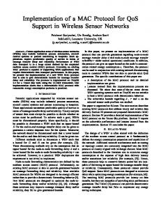
0.4 0.35
β=log(p)/log(ε)
max TSCS < TSCS
0.5 0.45
(5)
b
Pdesynch = p
TG /rdmax Tsynch
c
(7)
Given a reliability upper bound ² on Pdesynch , (7) yields an upper bound for Tsynch that takes losses into account. Tsynch
TSCS + TFmax
0.3 0.25
−1
10
0
10
p
Figure 2: Tsynch loss penalty as a function of synchronization algorithm failure probability p.
4.4
Design Procedure
We now present a design procedure that takes as input a hardware platform, a mesh network topology and a set of application requirements and yields TDM MAC protocol parameters that minimize protocol overhead. The application requirements consist of maximum SCS max duration TSCS , maximum DS duration TFmax , synchronization reliability ², and bounds on DS packet duration Dmin , Dmax min max and SCS packet duration DSCS , DSCS . The platform may support multiple data rates that correspond to different PHY modulation schemes. The synchronization algorithm operation during the SCS is characterized by execution time of P slots and a separate failure probability p for each data rate. The design procedure determines the MAC protocol parameters TG , Tsynch , D, DSCS , S, TF which minimize protocol overhead, meet the above requirements and satisfy the platform and synchronization design constraints. The design procedure consists of the following steps. Step 1. Perform bottleneck measurements on the platform to determine TP , TDpp and rdmax . Step 2. Determine TG , Tsynch , D and DSCS , that minimize protocol overhead, by solving the following optimization problem: MIN OVERHEAD: P (TP + DSCS + TG ) TP + TG + Tsynch TP + D + TG Subject to: Minimize
max TSCS − P (TP + DSCS ) P TG · log p + TG ) < Tsynch < rdmax · log ²
max(0, TDpp − TP − D) ≤ TG < TFmax + P (TP + DSCS Dmin ≤ D ≤ Dmax min max DSCS ≤ DSCS ≤ DSCS
Step 3. Compute S using TG , D, and TP in (1). Compute TF as an integer multiple of S. Finally, adjust Tsynch as TSCS plus an integer multiple of TF : TF = Sb
TFmax c S
(10)
Tsynch − TSCS c (11) TF The design procedure is flexible and has low complexity. It uses a few parameters to characterize the platform and synchronization algorithm and incorporates multiple packet sizes and multiple data rates. M IN OV ERHEAD uses linear constraints and only a few variables (TG , Tsynch , D and DSCS ). Hence, it can be solved efficiently using a standard optimization solver like MATLAB or CPLEX. The impact of different synchronization algorithms can be compared by solving M IN OV ERHEAD for each parameter pair (P ,p). Before the design procedure can be applied to our system, the synchronization algorithm that yields input parameters (P, p) must be specified. We describe our synchronization algorithm in the next section. f inal Tsynch = TSCS + T F b
5.
SYNCHRONIZATION ALGORITHM
In this section, we present an in-band synchronization algorithm for TDM multi-hop wireless networks that maintains the clocks of all MAPs accurately synchronized to a common time reference provided by the GWs. The GWs are synchronized to this time reference through out-of-band synchronization like GPS clocks. The algorithm is executed during the SCS and utilizes the TDM slotted structure to broadcast a synchronization beacon from the GWs to the MAPs in bounded time. For simplicity, we present an algorithm version that uses a single GW.
5.1
it is the first beacon it has received in the current SCS, computes an estimate of its clock offset to the GW clock and determines the beginning of the next Data Subframe (DS) based on the GW clock. It then re-broadcasts the beacon (unmodified) during its assigned slot in the SCS. The node discards other beacons it receives during the SCS. At the end of the SCS all nodes update their clocks based on their updated offset estimates. We now describe in detail the offset computation at each node upon reception of a beacon and the clock update actions performed by all nodes at the end of the SCS when the algorithm terminates. Offset computation. Suppose node n receives its first beacon at SCS slot i from node i. Let Tn (L) be the local clock value of node n when the beacon is received. Node n first computes an estimate Ti (L) of the time when node i sent the beacon:
Algorithm Description
During the SCS, all nodes use a pre-computed schedule of P slots. During each slot, a single node transmits and the rest are in receive mode. The first slot is assigned to the GW. Each node transmits at most once during the SCS. Fig. 3 shows the schedule that determines the node transmission sequence during the SCS. GW
4
Ts (L) = Ti (L) − (i − 1)SSCS
6
5
Of f set = Ts (R) − Ts (L)
SCS
...
(13)
(14)
Algorithm termination (clock updates). At the end of slot P of the SCS, each node n updates its local clock based on the newly computed offset. The reason for all nodes to simultaneously update their clocks at the end and not during the SCS is to avoid de-synchronization due to nodes updating their clocks with new clock values before others.
7
1 2 3 4 5 6 7
...
where δ is an estimate of the total delay for a beacon transmission from node i to node n. We measure δ offline using an experimental method that emulates a sender-receiver synchronization handshake protocol similar to [8]. The estimation uncertainty of δ is minimal due to the following reasons. First, we leverage our TDM implementation to remove nondeterministic medium access delay. Second, we timestamp the beacon at the MAC layer, bypassing uncertainties due to higher layers of the network stack at the sender. Third, propagation delay is negligible for distances encountered in typical wireless mesh networks. For example, in our implementation over 802.11 hardware the clock granularity is 1µs which equals the propagation delay at 300m. Given Ti (L), node n computes its estimate Ts (L) of the time when the GW node sent the beacon:
3
2
(12)
where SSCS is the SCS slot duration. Finally, node n uses the beacon timestamp value Ts (R) to estimate its offset with respect to the GW clock.
MAP
1
Ti (L) = Tn (L) − δ
SCS
...
Tsynch
Figure 3: An example 7-slot SCS for a 12-node mesh network (1 GW and 11 MAPs). Links denote ability to communicate (potentially with losses). Numbers in nodes denote their assigned Tx slot in the SCS. The algorithm begins when the GW broadcasts a beacon containing a timestamp of its current clock value at the first slot of the SCS. Each node that receives the beacon, provided
5.2
SCS slot sequence computation
Our synchronization algorithm requires each node to transmit at most once during the SCS. This property helps minimize the algorithm execution time. However, it introduces the problem of computing a sequence of node transmissions to disseminate the synchronization beacon to all nodes in the most reliable manner. The problem is combinatorial. In a mesh network of one GW and N MAPs, the optimal solution can be found by enumerating and testing N! sequences– complexity becomes prohibitive as the network size increases. In this section we provide a heuristic to construct the SCS slot sequence. The algorithm uses a set of measured packet
loss rates of all links in the mesh network. Such measurements can be performed at O(N ) complexity using broadcast packets [6, 11]. Our algorithm uses the link loss rates pl to construct a tree rooted at the GW that yields a maximum reliability path (or minimum loss path) toward each MAP. The reliability of each path s is the Q product of packet success rates of its intermediate links l: l∈s (1 − pl ). Maximizing path reliability from GW to each MAP is equivalent to maximizing log path reliability. Log path reliability results to addition of log success rates over the path. Hence, the tree can be constructed by running N times Dijkstra’s shortest path algorithm between the GW and each MAP. We estimate Qthe synchronization algorithm failure probability p as 1 − l∈sm (1 − pl ), where sm is the minimum-reliability (maximum-loss) path in the tree. The slots of the SCS sequence are assigned to nodes by traversing the tree in a breadth-first manner. For each node’s slot, this assignment ensures at least one neighbor node transmitted a beacon at a previous slot. The leaf nodes do not need to be assigned an SCS slot because they are covered by the rest of the nodes. As an example, the SCS sequence in Fig. 3 has been constructed assuming certain packet loss rates on the links. We emphasize that the tree is constructed only to determine the SCS slot sequence. During the algorithm execution the beacon is disseminated through broadcasting.
5.3
Discussion
The algorithm execution time P may vary from 1 slot (when all MAPs are within range of the GW) to N slots (when there is only a single path from GW to all MAPs). In large networks execution time can be decreased by running the synchronization algorithm in parallel at multiple network regions, where each region has been assigned to a different GW and channel. Further reduction in execution time can be achieved by modifying the algorithm to exploit spatial reuse. This would require a more sophisticated slot sequence computation and an interference model that predicts packet losses of links transmitting in parallel; such models can be built and still use O(N) measurements [6, 11]. Finally, if the delay bound on TSCS allows, the synchronization algorithm reliability can also be increased by running multiple copies of the SCS sequence within a single algorithm execution. We plan to investigate these optimizations in our future work. Our implementation on an 8-node wireless testbed demonstrates that this algorithm synchronizes the network with a very low execution time and negligible overhead (Section 8). Apart from low execution time, the algorithm simplicity allows efficient integration and implementation with the TDM MAC protocol state machine. We proceed to describe this integration in the following section.
6.
SYSTEM INTEGRATION
In this section, we integrate our synchronization algorithm with the mesh TDM MAC protocol architecture of Section 3. We aim at a design of low-complexity, using a minimum number of timers. We first describe the two timers we used and then present the integrated protocol flow using a simplified flow diagram of the TDM MAC protocol state machine.
receive beacon set DS_TIMER
...
... CS A
...
DS B
C
D
Figure 4: Sequence of phases within a TDM frame. 6
1 process incoming packet
packet interrupt received
10
7 no
received was first beacon?
2
wait for packet interrupt or timer expiration
3 was it the last SCS slot?
SLOT_TIMER expired
SCS_TIMER expired
no
yes
set SLOT_TIMER
4
11 stop
SLOT_TIMER
slot type lookup
no SCS_TIMER active?
RX
TX yes
yes 8
5
12 compute clock offset
wait for SCS_TIMER to expire
13
9 set SCS_TIMER
transmit packet(s)
SCS_TIMER expired apply new clock
Figure 5: State diagram of the integrated TDM protocol operations.
6.1
Protocol Timers
A system with perfect clocks could implement the TDM protocol operation through synchronization using a single slot timer. However, due to imperfect clocks, additional mechanisms are needed to keep nodes synchronized. We provide a simple design of the integrated system using only two timers. The SLOT TIMER is the basic timer. It is set at the start of each slot and its timeout is equal to the slot duration. Since we need to periodically compute the clock offset and update the clocks, we use an additional timer called SCS TIMER. This timer is set at beacon reception and expires at the end of the SCS according to the GW’s clock. This timer ensures that all nodes are synchronized at the end of the SCS.
6.2
Integrated protocol operation
During each SCS, each TDM node transitions through four protocol phases, as illustrated in Figure 4. • Phase A: Node is in SCS and it has not yet received a beacon. • Phase B: Node is in SCS and it has received a beacon. This phase might not exist in a cycle, if the node receives no beacon due to low link quality. • Phase C: Node is in the last slot of SCS. • Phase D: Node is in a DS. The MAC state diagram in Figure 5 illustrates the flow of protocol transitions. We proceed to describe the flow of each of the phases A-D. In all four phases, the node always starts from state 1, waiting for a timer to expire.
Phase A. In this first phase, a node is in the SCS and it has not yet received a synchronization beacon. For each SCS slot until it receives a beacon, a node’s SLOT TIMER expires and the only node action is to set a new SLOT TIMER to expire in the next SCS slot. A node thus follows the flow [1, 2, 3, 4, 1] in Fig. 5. Upon the first beacon reception in the SCS, the node performs the clock offset computation relative to the GW’s clock. It then uses this offset to set the SCS TIMER to expire at the end of the last SCS slot. Note, however, that for the rest of the SCS, the node will still use its local (possibly drifted) clock. Since the SCS TIMER is set using the new clock offset, it will expire simultaneously at all nodes (see Phase C). The flow for the beacon reception is [1, 2, 3, 4, 1, 6, 7, 8, 9, 1] in Fig. 5. Phase B. In this second phase, a node is in an SCS slot other than the last SCS slot and it has already received a synchronization beacon. In all the remaining SCS Rx slots, a node will simply ignore any additional synchronization beacons it may receive (following the flow [1, 2, 3, 4, 1, 6, 7, 1]). Upon its own SCS Tx slot, a node will re-broadcast the (first) synchronization beacon (containing the GW’s timestamp) that it received in a previous SCS slot. This corresponds to the flow [1, 2, 3, 4, 5, 1] in Fig. 5. Phase C. In this third phase, the SCS ends and all nodes must apply the new clock and then simultaneously start the first DS slot. At the beginning of the last SCS slot, the SLOT TIMER timer is set to expire according to the node’s local clock. If the node had received a beacon during the SCS, the SCS TIMER was set to expire in Phase A according to the node’s old clock. If a node’s clock is faster than the GW clock, the SLOT TIMER will expire before the SCS TIMER. In this case, the node will wait for the SCS TIMER to expire and apply the new clock. If a node’s clock is slower than the GW clock, the SCS TIMER expires first and the node then immediately cancels the SLOT TIMER and applies the new clock. Applying the new clock based on the SCS TIMER ensures that, regardless of the individual nodes’ clock drifts, all nodes are now synchronized and simultaneously start the DS. The two different flows described above are [1, 2, 11, 12, 13, 3, ..., 1] and [1, 10, 13, 3, ..., 1] in Fig. 5, respectively. After the application of the new clock, the first DS slot starts. The handling of a DS slot is identical independent of whether or not it is the first DS slot. We refer to Phase D for a description of the flows in DS. If the node had not received a beacon during the SCS, its SCS TIMER was not set in Phase A. Thus, the node will trigger the end of SCS using the SLOT TIMER. This is flow [1, 2, 11, 3, ..., 1] in Fig. 5. The node thus uses its local clock until the next SCS when it receives a beacon. Phase D. In this final phase a node is in a DS. In this phase, each new slot is triggered by the expiration of the SLOT TIMER. The node sets a new SLOT TIMER and then determines whether the current slot is of Tx or Rx type. Since nodes know their schedule in advance, a fast table lookup for the current slot ID is enough to provide the required information about the current slot2 . In case of a Tx slot, the node transmits any data packets that are readily available in its outgoing queue and can fit within the cur2
The same lookup is performed during SCS in Phases A-C.
rent slot. In case of a Rx slot, the node processes any data packet(s) received during the slot. The flows in this phase are [1, 2, 3, 4, 5, 1] and [1, 2, 3, 4, 1, 6, 7, 1] in Fig. 5 for Tx slots and Rx slots, respectively.
7.
PROTOTYPE IMPLEMENTATION
In this section, we first overview the architecture of our 802.11 wireless programmable platform. We then highlight the required modifications to its IEEE 802.11 CSMA MAC implementation to realize our TDM MAC protocol on this platform.
7.1
WiLD MAC Platform
WiLD MAC is a standard-compliant IEEE 802.11a/b/g platform. Figure 6 gives an overview of the WiLD MAC architecture. The MAC protocol is divided in Higher MAC and Lower MAC. The Higher MAC handles low-priority tasks such as configuration and management. The Lower MAC is the part where we have implemented the TDM MAC protocol and measured the platform bottlenecks. The Lower MAC performs time critical tasks such as frame transmission and reception. It primarily consists of the Packet Processing (PP) and the Tx Rx Coordination (TRC) modules. The PP module receives packets from the network layer and performs encryption/decryption, before delivering them to the TRC. The TRC is the last step traversed by a data packet in the data path before it is delivered to the PHY layer. The TRC is also the last point where we can have access to a packet. The TRC implements time-critical 802.11 functions that typically require response time of a few microseconds. It is interrupt-driven and communicates with the Burst Processor (BuP) for packet transmission and reception.
Figure 6: WiLD MAC platform architecture. The BuP is a dedicated processor for packet transmission and reception, realized in hardware. It implements the most time-critical 802.11 functions (e.g., frame acknowledgement), and contains registers for timers and counters (e.g., backoff and NAV). The TRC decides the appropriate values for these counters and timers, writes the registers and then the BuP performs the countdown. The BuP signals through an interrupt to the TRC when a value has reached zero.
The WiLD MAC firmware is implemented in ANSI-C. In contrast to existing off-the-shelf 802.11 wireless cards, WiLD MAC platform provides access to the complete firmware code. We proceed to describe our modification to the firmware required to realize our protocol.
Application of Design Framework
We apply our design framework in Section 4 to determine the TDM MAC protocol parameters for our wireless plat-
4
5 6
First floor
7
8 56m
Figure 7: Wireless testbed. form and testbed deployment. We follow the design procedure described in Section 4.4 to account for design constraints due to platform bottlenecks and synchronization algorithm operation under packet losses.
8.1.1
Packet loss measurements and SCS sequence computation
Figure 8 depicts measured packet loss rates for all links in our testbed at 54 Mbps data rate. In each measurement experiment, nodes were sequentially scheduled to continuously transmit broadcast packets for 60 seconds each, while all other nodes recorded the received packets. Each data point is the average for each link across 10 experiments on multiple days. This profile contains links with 0 or 1 packet loss rate but also links of intermediate quality. Similar profiles have been observed in outdoor 802.11 mesh networks [2]. We used these measurements to seed the SCS construction 1 0.9 0.8
DESIGN AND PERFORMANCE EVALUATION ON A WIRELESS TESTBED
We design and evaluate our TDM MAC protocol on a wireless testbed of 8 nodes deployed in an office building of two floors and a mezzanine (Fig. 7). The first floor contains cubicles with thin separations. The second floor contains multiple rooms separated by both thin and thick walls. Each node consists of a laptop connected via Ethernet to a WiLD board, equipped with an integrated omni-directional antenna. All boards are configured to operate in ad hoc mode with transmission power set to 30mW. We design our system in an environment where external interference is mitigated. All experiments are performed in channel 60 of 5GHz band (802.11a) during nights and weekends. As an extra measure, before each experiment we used sniffers to ensure that no other 802.11a networks existed in this channel.
8.1
3 Mezzanine
TDM MAC Protocol Implementation
In this section, we describe our modifications to the WiLD MAC to realize the TDM MAC protocol in Section 6. We disabled native 802.11 CSMA protocol functions such as carrier sensing, NAV, backoff, and RTS/CTS. The carrier sensing is disabled/enabled through manipulation of a hardware register. With all the above functions disabled, data packets can be transmitted at a given time instant that we control through the TRC. We modify the TRC to program the BuP to set a ”pending transmission flag” as soon as it finished preparing a packet. Then, at the start of each Tx slot the TRC checks this flag. If the flag is set, the TRC programs the BuP for transmission. The transmission will start after the inter-frame spacing requirement has timed out. We were not able to completely disable inter-frame spacing, but we modified it to always take the minimal allowed value, which in our case is equal to SIFS. Both DS and SCS Tx slots are scheduled by setting hardware timers in the BuP. The SLOT TIMER is set at the start of each slot based on the local clock. The SCS TIMER is set upon reception of a synchronization beacon, using the GW’s clock in the beacon. Upon SCS TIMER expiration, the local clocks are synchronized by adjusting their clock offset. In addition to data packet transmissions and to cope with the high loss rates encountered in mesh networks we implemented an ACK-based retransmission mechanism similar to 802.11. The main difference is that our mechanism does not perform exponential backoff when a packet fails. Depending on the slot duration that we configure, it can retransmit the packet in the same slot or in the next slot. We proceed to measure our design and protocol parameters and to evaluate our TDM MAC on a testbed.
8.
Second floor
1
Packet loss rate
7.2
2
0.7 0.6 0.5 0.4 0.3 0.2 0.1 0
10
20
30
40
50
Link index
Figure 8: Average link packet loss rates at 54 Mbps in our testbed. algorithm in Section 5.2. Table 1 shows number of SCS slots P and synchronization algorithm failure probability estimates p for all GW choices. We selected as GW node 5 which provides minimum P and relatively low p. GW
1
2
3
4
5
6
7
P
3
3
3
2
2
4
3
8 3
p
0.23
0.43
0.33
0.41
0.30
0.62
0.51
0.42
Table 1: SCS construction algorithm number of slots P and failure probability estimates p for all GW choices.
8.1.2
TDM MAC Protocol Parameter Determination
We now apply the procedure of Section 4.4 to design the TDM protocol with the requirements of Table 2, which also depicts the procedure steps and their outcomes. Below we describe our measurement methodologies and findings during each step of the design procedure. Step 1. We first measure the platform bottlenecks rdmax , TP , and TDpp on the WiLD boards, before the testbed deployment. The measurement methodologies were implemented at the Lower MAC (where the protocol is implemented) and used high-accuracy timers and interrupts. Clock drift rate, rdmax . We measured the clock drift rate for each node pair A and B by periodically sending timestamped packets from A to B. For each received packet, B computed and stored (i) its local clock (ii) the offset equal to the difference of its local clock and the timestamp in the packet. The clock drift rate of B with respect to A, was computed offline as the slope of the offset evolution over time. This procedure was performed at different locations and times for each pair A and B. Fig. 9 depicts the measured average drift rates for all node pairs. For each node pair, the drift rate has low variability over time and locations. Across node pairs the drift rate ranges from 0.1 to 5.5 µs/s. In our design, we use the maximum observed drift rate rdmax = 5.5µs/s. .
D = 300 µs at 54Mbps data rate. These two values and the values P = 2, p = 0.3 (corresponding to GW node 5 in Table 1) were used in M IN OV ERHEAD optimization problem to yield TG and Tsynch . Step 3. Application of (1), (10) and (11) determined the final values of S, Tsynch and TF as shown in Table 2.
Synchronization algorithm Step 1 Step 2
Step 3
Drift rate (µs/s)
5
4
3
2
1
0 0 1
5
10
15
20
25
29
Node pair index
Figure 9: Drift rates for all node pairs AB in our testbed. Only the positive drift rates rdAB are shown (the negative drift rates are rdBA = −rdAB ) Slot processing, TP . We measured TP on each board as the difference between the SLOT TIMER interrupt signaling the start of the TDM slot and the TtxStart interrupt signaling the start of the transmission by the BuP. Extensive measurements on each board and across boards, yielded TP = 17 ± 1 µs. Data packet preparation time, TDpp . We measured TDpp through back-to-back transmissions of minimal-duration data packets timstamped at sender A and stored by receiver B. The time difference between consecutive timestamps included the slot processing overhead TP plus packet duration D at node A. Minimal packet duration D exposed the packet preparation bottleneck TDpp (the system operated under TDpp > TP + D). Extensive measurements at each board and across boards, yielded TDpp = 104 ± 1 µs. Step 2. In our implementation, we use 802.11 beacons (LSCS = 52 bytes) and the maximum 802.11 MAC packet (1530 bytes) for each TDM slot. According to 802.11a OFDM PHY, these sizes correspond to durations DSCS = 28µs and
TFmax 5000µs LSCS 52 bytes TP 17 µs D 300 µs Tsynch 95064µs TF 4845 µs
² 10−4 p 0.3 TDpp 104 µs
Datarate 54 Mbps
TSCS 102 µs Tsynch 92157µs
Table 2: Design procedure steps and outcomes. The resulting TDM MAC protocol is efficient. Its overG head is 7.22%, consisting of slot overhead TP +T = 7.12% S TSCS and negligible synchronization overhead Tsynch = 0.1%. Furthermore, the algorithm execution time TSCS of 102 µs max is well below the TSCS delay bound of 5000 µs.
8.2 6
max TSCS 5000µs P 2 rd 5.5 µs/s DSCS 28 µs TG 6 µs S 323 µs
Requirements
Synchronization Algorithm Validation
In this section, we validate our synchronization algorithm and evaluate its accuracy in terms of maximum clock drift over all node pairs. In these experiments only synchronization beacons are transmitted (during the SCS) at 54Mbps according to the designed synchronization period Tsynch . Instead of the designed protocol’s beacon slot duration we used the larger data slot duration S = 323µs This provides a large guard time to observe potentially high clock drifts without de-synchronizing the network. During each experiment all nodes store their gateway offset at the end of each synchronization period. The maximum clock drift over all nodes that received a beacon at each beacon period is computed offline based on their offset differences, in a similar manner to our clock drift rate measurement methodology. Fig. 10 depicts the cdf of 24000 clock drift samples, spanning several 2-minute measurement intervals across four days. 1 0.9 0.8 0.7 0.6 0.5 0.4 0.3 0.2 0.1 0
1
2
3
4
5
6
7
8
9
10
Maximum clock error (µs)
Figure 10: CDF of maximum clock drift (error) for Tsynch = 92157µs, across four days. The maximum observed clock drift was 10µs and only 7 out of 24000 samples exceeded the designed guard time
TG = 6µs. This is the same order of magnitude as the reliability requirement ² = 10−4 . The majority of the clock drift samples do not exceed 4µs, which is less than the designed guard time TG = 6µs. This overestimation is due to the synchronization design constraints that use the conservative analysis of Section 4.3. We conclude that the synchronization algorithm achieves high accuracy and uses a slightly conservative guard time.
Performance evaluation
We focus on two aspects that have not yet been explored in a mesh TDM MAC protocol implementation: the impact of slot duration S and the impact of packet losses on the operation of a mesh TDM MAC protocol. We use throughput, mean delay, and delay variance (jitter) as performance metrics. All experiments use the TDM MAC parameters in Table 2. Each reported data point is the average of ten experiments.
8.3.1
Impact of slot duration
Existing TDM MAC implementations operate with slot duration S of tens to hundreds of milli-seconds. We investigate performance at smaller time scales, enabled by our implementation. Our setup involves two bidirectional flows between the GW and a MAP in our testbed, configured to transmit in alternate slots. We have implemented and enabled multi-packet transmissions within a slot. To isolate impact of slot duration, we selected a link with good quality in both directions. We consider both TCP and backlogged UDP traffic. S 323µs 1ms 10ms
Aggregate Throughput (Mbps) 34.8 33.0 29.2
Delay (ms) 0.6 0.7 0.8
Loss rate (%) 0 20 60
Aggregate Throughput (Mbps) 21.7 18.7 18.4
Delay (ms) 1.5 1.7 2.1
Delay (ms) 0.8 1.0 5.2
Jitter (ms) 0.8 2.0 12.0
Aggregate Throughput (Mbps) 34.8 28.3 11.9
Delay (ms) 0.6 0.8 1.9
Jitter (ms) 0.1 0.3 2.6
Table 6: Impact of packet loss on TDM MAC UDP performance. only two nodes. As the number of nodes sharing the TDM frame increase, performance can further degrade.
8.3.2
Throughput comparison to 802.11 MAC
Fig. 11 depicts a scatterplot comparing throughput for several one-hop and two-hop bi-directional flows in our testbed. Each point corresponds to the throughput of each uni-directional flow under TDM (y-axis) and 802.11 (x-axis). Points of the same shape correspond to throughput of uni-directional flows that belong to the same bi-directional flow. We observe that the TDM MAC provides higher throughput perdirection (most points are above the y=x line). In addition, the TDM MAC distributes throughput more fairly to the unidirectional parts of each bi-directional flow: two points of the same shape typically have much less vertical distance than horizontal distance.
Jitter (ms) 0.1 0.6 3.9
18 16
Table 3: Impact of slot duration: UDP results. S 323µs 1ms 10ms
Aggregate Throughput (Mbps) 27.8 23.5 4.3
Table 5: Impact of packet loss on 802.11 MAC UDP performance.
TDM throughput (Mbps)
8.3
Loss rate (%) 0 20 60
Jitter (ms) 11.7 9.4 16.9
14 12 10 8 6 4 2
Table 4: Impact of slot duration: TCP results.
0 0
2
4
6
8
10
12
14
16
18
801.11 Throughput (Mbps)
As expected, the UDP results in Table 3 show that S does not affect a lot throughput and average delay. However, as S increases, the jitter increases because at large slot durations packets experience small delays within a slot but large delays across slots, when the other side is transmitting. The TCP results in Table 4 show throughput degradation and increased jitter for large S. This is due to the TCP selfclocking and backoff mechanisms. When S is large, the TCP ACKs are delayed and this affects maximum TCP sending rate. The increased jitter results from TCP erroneously activating congestion control and backoff due to delayed TCP ACKs instead of packet loss. Also note that, depending on the TCP state, in some slots there might no TCP traffic or only TCP ACKs to send. This further contributes to the TCP throughput degradation. We conclude that S should be minimized to the extent possible. Note that these measurements were performed with
Figure 11: Throughput comparison of TDM MAC and 802.11 for one-hop (upper right region) and two-hop (lower left region) bi-directional flows.
8.3.3
Impact of losses
In this section we study how packet loss impacts the performance of the TDM protocol and how this performance compares to 802.11 MAC. We investigate the impact of three different link characteristics in our testbed (c.f. Fig. 8): low loss, medium loss (average 20% loss) and high loss (average 60% loss) links. Single link, multi-flow performance. We first examine single-link bidirectional communication between different node pairs in our testbed. Table 5 and Table 6 show the UDP performance resulting from packet loss experiments
for 802.11 MAC and our TDM MAC, respectively. The 802.11 performance degrades rapidly with increased packet loss. The main reason is that 802.11 MAC performs retransmissions using binary exponential backoff. Even if eventually a retransmission succeeds, a significant amount of time has been lost. On the other hand, the TDM MAC performs retransmissions at each assigned slot. According to Table 6 this results in graceful performance degradation for the TDM protocol even in the high loss scenario. Multi-hop, multi-flow performance. We consider a chain topology of four nodes and evaluate the performance of three UDP flows operating in parallel from the gateway node to the three downstream nodes. Figures 12(a) and 12(b) show the throughput performance of the three flows with different packet loss behavior on the link from the gateway to the first node on the chain. We observe that for all loss rates both protocols TDM achieves higher throughput than 802.11. Furthermore, as loss increases, 802.11 performance degrades rapidly due to binary exponential backoff while TDM experiences graceful performance degradation. 1−hop flow 2−hop flow 3−hop flow
5 4 3 2 1 0
1−hop flow 2−hop flow 3−hop flow
6
Throughput (Mbps)
Throughput (Mbps)
6
5 4 3 2 1
0%
20% Packet loss
60%
(a) TDM
0
0%
20% Packet loss
60%
(b) 802.11
Figure 12: TDM and 802.11 downstream performances.
9.
CONCLUSIONS
We presented the design, implementation, and evaluation of a slotted TDM MAC protocol for multihop wireless mesh networks using a programmable 802.11-based platform. We introduced a design procedure that optimizes the protocol parameters given platform communication bottlenecks and synchronization constraints. We designed a novel multi-hop clock synchronization algorithm that utilizes the protocol’s slotted structure to achieve accurate micro-second level synchronization with low overhead and bounded execution time. We integrated this synchronization algorithm with the TDM MAC protocol state machine, using minimal hardware resources. We prototyped this protocol on our programmable platform and applied our design framework to optimize its operation. We experimentally validated its correct operation, including the chosen protocol parameters and the synchronization algorithm, and demonstrated its performance under realistic network configurations and traffic patterns. To the best of our knowledge, this is the first comprehensive design and implementation of a mesh TDM MAC protocol at firmware level which enables communication and control at microsecond granularity. In summary, we believe that the design guidelines presented in this paper along with their experimental validation on a real platform make up the missing piece of the TDM MAC design and implementation as a contender for high-performance MAC in mesh networks.
10.
REFERENCES
[1] ECMA 368, High Rate Ultra Wideband PHY and MAC standard, 2007. [2] D. Aguayo, J. Bicket, S. Biswas, G. Judd, and R. Morris. Link-level Measurements from an 802.11b Mesh Network. In Proc. ACM SIGCOMM, Portland, OR, Aug. 2004. [3] K. Chebrolu, B. Raman, N. Mishra, P. Valiveti, and R. Kumar. Brimon: a sensor network system for railway bridge monitoring. In Proc. ACM MobiSys, Breckenridge, CO, USA, Jun. 2008. [4] J .Elson. Time synchronization in wireless sensor networks. PhD Thesis, UCLA, 2003. [5] S. Ganeriwal, R. Kumar, and M. Srivastava. Timing-sync Protocol for Sensor Networks. In Proc. ACM SenSys, Los Angeles, CA, USA, Nov. 2003. [6] A. Kashyap, S. Ganguly, and S. Das. A Measurement-based Approach to Modeling Link Capacity in 802.11-based Wireless networks. In Proc. ACM MobiCom, Montreal, Canada, Oct. 2007. [7] M. Maroti, B. Kusy, G. Simon, and A. Ledeczi. The Flooding Time Synchronization Protocol. In Proc. ACM SenSys, Baltimore, MD, USA, Nov. 2004. [8] D. Mills. Internet time synchronization: The network time protocol. IEEE Transactions on Communications, 39:1482–1493, 1991. [9] M. Neufeld, J. Fifield, C. Doerr, A. Sheth, and D. Grunwald. SoftMAC: - Flexible Wireless Research Platform. In HotNets, College Park, MD, USA, Nov. 2005. [10] R. Patra, S. Nedevschi, S. Surana, A. Sheth, L. Subramanian, and E. Brewer. WiLDNet: Design and Implementation of High Performance WiFi Based Long Distance Networks. In Proc. NSDI, Cambridge, MA, USA, Apr. 2007. [11] L. Qiu, Y. Zhang, F. Wang, M. Han, and R. Mahajan. A general model of wireless interference. In Proc. ACM MobiCom, Montreal, Canada, Oct. 2007. [12] B. Raman and K. Chebrolu. Design and Evaluation of a New MAC Protocol for Long-Distance 802.11 Mesh Networks. In Proc. ACM MobiCom, Cologne, Germany, Aug. 2005. [13] A. Rao and I. Stoica. An Overlay MAC Layer for 802.11 Networks. In Proc. ACM MobiSys, Seattle, WA, USA, Jun. 2005. [14] K. Romer, P. Blum, and L. Meier. Time Synchronization and Calibration in Wireless Sensor Networks. Book chp., Handbook of Wireless Sensor Networks, Wiley Series on Parallel and Distributed Computing, 2005. [15] A. Rowe, R. Mangharan, and R. Rajkumar. Rt-link: A Time-Synchronized Link Protocol for Energy-Constrained Multi-hop Wireless Networks. In Proc. IEEE SECON, San Diego, CA, USA, Jun. 2006. [16] A. Sharma, M. Tiwari, and H. Zheng. MadMac: Building a Reconfigurable Radio Testbed Using Commodity 802.11 Hardware. In IEEE Workshop on Networking Technologies for Software Defined Radio (SDR) Networks, Portland, OR, USA, Nov. 2006. [17] USCG Navigation Counter GPS page. http://www.navcen.uscg.nil/gps/default.html.