Recent Research Developments in Learning Technologies (2005)
1 2 3 4 5 6 7 8 9 10 11 12 13 14 15 16 17 18 19 20 21 22 23 24 25 26 27 28 29 30 31 32 33 34 35 36 37 38 39 40 41 42 43 44 45 46 47 48 49 50 51 52
1
Teaching Assembly Language Using a Robot Simulator as Part of a Course on Computer Structure P.A. Castillo *1, M. García-Cruz 1, J.J. Castillo-Valdivieso 2 , A. Cañas 1 and B. Prieto 1 1 2
Dpto. de Arquitectura y Tecnología de Computadores, 18071 Universidad de Granada, Spain Dpto. de Tecnología, IES Europa, Aguilas, Murcia, Spain
Most students find learning assembly language a difficult task due to the fact that it is a low-level programming language. As operating systems and visual programming languages evolve, the importance of studying assembly language becomes increasingly difficult to justify. Experience has shown the need to make practice sessions more appealing to students studying low-level programming languages as part of course on Computer Structure. Through learning to control a simulated robot, students are stimulated to make an effort to learn and improve the necessary skills required for 80x86 assembly programming. This paper presents a robot simulator requiring remote guidance using an external program. The proposed robot model uses three sensors, two actuators (to move the wheels) and a control system. Keywords computer structure, assembly language, robot simulator.
1. Introduction The ‘Computer Structure I’ module, subject imparted by the University of Granada, studies machine language and focuses on 80x86 architecture. The practice sessions are primarily centred on assembly language. Due to the availability of new operating systems and frameworks for visual programming, it is difficult to justify practice sessions at assembler level. Despite the advantages this language presents (i.e. in generating specially adapted machine programs which results in optimum speed and use of resources), its study must be presented to the students in an attractive way. This paper presents a tool to simulate an autonomous robot that must be controlled using an external program, which can be made as complex as desired. It is possible, for example, to make the robot carry out complicated operations such as negotiating labyrinths, avoiding obstacles and cleaning remainders. The robot simulator has three sensors: front, right and left sides that calculate the distance to the nearest object in those directions and within a maximum range. The robot moves in its environment using two independent motors which receive the necessary spin value for each wheel. If the values are identical, it will move in the same direction, whereas different values entail a turn. The program simulates the robot movements using the commands sent by an external control program. Both programs are synchronised through two text files. The simulator records the sensor values according to the distance from obstacles and the control program uses these values to make the wheels turn. As well as the text files and synchronization, rules to determine how the robot will move depending on the obstacles it is faced with must also be implemented. In the practice sessions students are encouraged to program and develop several strategies to determine how the robot must behave according to its environment. The control program is developed in assembly language, in order to learn this language and the 80x86 architecture. The program could be equally applied on a real robot based on Intel architecture (currently a pilot project). Once the students dominate assembly programming, they are then able to program the I/O PC ports to read sensor values and to activate the motors. The simulator has been developed in C++, using the gtkmm2 [1,2] graphic programming library. Thus, the program can be easily compiled and used on Windows and Linux/Unix platforms. *
Corresponding author: e-mail:
[email protected], Phone: +34 958240589
© FORMATEX 2005
2
1 2 3 4 5 6 7 8 9 10 11 12 13 14 15 16 17 18 19 20 21 22 23 24 25 26 27 28 29 30 31 32 33 34 35 36 37 38 39 40 41 42 43 44 45 46 47 48 49 50 51 52
P.A. Castillo et al.: Simulator of robot to teach the assembler language for the course of computer structure
The rest of this paper is structured as follows: Section 2 describes the simulator; Section 3 describes the control operation and finally, in Section 4, a brief conclusion and planned work are presented.
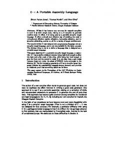
Fig. 1 Snapshot showing the control program as it sends commands to the robot simulator. The command window can be seen in the lower part of the screen. In this case, the environment through with the robot moves is a labyrinth. The simulator shows detailed information about its status and the commands it receives. The green box corresponds to the target the robot must reach.
2. The simulator The system consists of two programs: a simulator that shows the robot environment (a graphics program that shows output messages on the command window where it was run), and the control program (second command window). The system operation is as follows: 1. Synchronization between both programs is carried out using two files: S and A. 2. The simulator creates a graphic window which shows the robot’s location. Then, it calculates the three sensor values, distance and angle to the target point (green spot), and records those values in the S file. 3. The control program waits for these values and reads them from the file character by character until a space is found (text mode). After sensor values, distance and angle have been read as text strings, they must be transformed into integer numbers. 4. The controller processes these values and sends a command to the robot, which will depend on where the obstacles are located. This command specifies the degree that each wheel must turn. 5. Once the command is calculated, it is saved in the A file as a text string representing two integer numbers in the range [0 - 99].
© FORMATEX 2005
m-ICTE2005 http://www.formatex.org/micte2005
1 2 3 4 5 6 7 8 9 10 11 12 13 14 15 16 17 18 19 20 21 22 23 24 25 26 27 28 29 30 31 32 33 34 35 36 37 38 39 40 41 42 43 44 45 46 47 48 49 50 51 52
3
This kind of synchronization makes it much easier to port the system between operating platforms and even to communicate with programs running on different systems (i.e. through a NFS file system). The aspects the students must learn in order to program the control are: • Screen I/O • File I/O • Complex control structures to implement synchronization • Integer number calculation • Data format translation between different representations • Robot guidance strategy
3. Using the simulator Versions for both Linux and Windows have been developed. Thus, the practice exercise can be conducted on both operating systems. In fact, during the second year that the exercise was proposed, some of the students developed their controls under Linux (using NASM [5,6]) while others opted for Borland’s TASM [7,8] under Windows. Different versions of the simulator (for Linux and Windows) can be downloaded from the following URL: http://atc.ugr.es/~pedro/docencia/simulador/ The simulator program has several options: to set the simulator operation, to change the environment or to move some of the obstacles: • “Paso” (Step): once the simulator program is started, it remains on standby until a command is given. It can either be run step by step, or continuously by clicking the appropriate button. In each step, communications between controller and simulator take place: the simulator sends sensor values to the controller and receives a command to execute. Once the command is given and the robot moves, the simulator stops and waits for the next step. • “Continuo” (Continuous): communications are carried out continuously which means that the simulator will not stop unless the ‘Step’ button is clicked or the control program sends a control code ordering the simulation to end. • “Información” (Information): the simulator program shows some information about the robot and target coordinates, distances and angles, the environment, etc. • “Escenario” (Environment): changes the environment, obstacles and target. Movable obstacles change from an environment to another. • “Obst .móvil” (Movable Obstacles): usually, obstacles will remain fixed. However, if this button is clicked, some of the obstacles will move, making it more difficult for the robot to negotiate its way through its environment. • “Reiniciar” (Reset): to test several control programs under the same conditions, the simulator state should remain constant. Thus, clicking this button, the number of steps is set to zero, and the robot and obstacles are placed in their initial coordinates. • “Acerca de” (About): displays information on the simulator. • “Salir” (Exit): exits the program.
4. Conclusions and Future work Learning assembly language is a complex task for students. Moreover, most of them are unable to appreciate the advantage of its study. However, proposing interesting programming activities for practice sessions generally results in a more positive attitude. As the sometimes tedious task of learning assembly programming suddenly becomes more attractive. This paper presents a robot simulator that has been developed with this idea in mind. The student is required to develop a control program that receives the sensor values and sends commands to the robot to enable it to move through its environment according to a designed strategy.
© FORMATEX 2005
4
1 2 3 4 5 6 7 8 9 10 11 12 13 14 15 16 17 18 19 20 21 22 23 24 25 26 27 28 29 30 31 32 33 34 35 36 37 38 39 40 41 42 43 44 45 46 47 48 49 50 51 52
P.A. Castillo et al.: Simulator of robot to teach the assembler language for the course of computer structure
Fig. 2
Snapshot showing the simulator controls.
Until now, experiences have been very positive: many student groups have successfully developed control programs to guide the simulated robot. They used ‘assembler’ programs in Linux as well as in Windows. Note that most of them used Linux, although their knowledge of this system was not as good and involved making an extra effort. However, it was very encouraging to see how their programs controlled the robot in solving labyrinths, detecting and avoiding objects. Nowadays, a real robot with a built-in Intel 8086 microprocessor is under development. It will be interesting to test the control programs designed by students on a real life robot instead of on a simulator.
5. Further information The simulator, both in the Linux and Win32 versions, is available for download at the following Web page: http://atc.ugr.es/~pedro/robot Acknowledgements
This work has been supported by CICYT TIC2003-09481-C04-04 project.
References [1] Rodríguez-Roselló, M. A.: "8088-8086/8087. Programación ensamblador en entorno MSDOS". Anaya Multimedia, (1993). [2] Beltrán de Heredia, J.: "Lenguaje ensamblador de los 80x86" Anaya Multimedia. Colección Guías prácticas para programadores. ISBN: 84-7614-622-1 [3] http://www.gtkmm.org [4] http://gtkmm.sourceforge.net/gtkmm2 [5] http://nasm.sourceforge.net [6] http://nasm.2y.net [7] http://info.borland.com/borlandcpp/cppcomp/tasmfact.html [8] http://www.beroset.com
© FORMATEX 2005