Bangalore, India, where he was section manager for simulation. He was ... and digital systems, and software, such as classic procedural. PASCAL .... 3): this is the call of subtree element. ..... as Visiting Professor at the Center for Reliable.
IEEE TRANSACTIONS ON EDUCATION. VOL. 36, NO. I , FEBRUARY
152
vices in organization development and for teaching programs in colleges of engineering, medicine, science, and graduate studies. He was on sabbatical leave at the University of Illinois Urbana, IL, and the Illinois Institute of Technology Chicago, IL, during the academic year of 1981-1982. In August 1985, he joined Wilkes University, Wilkes-Barre, PA, where he is currently a Professor of Electrical Engineering. He is presently studying mobility limiting mechanisms in high-speed devices, including quantum and highfield effects. He has visited several international institutions and enjoys the privilege of knowing the cultures and educational methods being practiced around the globe. He participated in the Sakaki Quantum Wave Project involving the design of Quantum Well Wire FET‘s at the University of Tokyo under the Exploratory Research for Advanced Technology (ERATO) Program. Presently, he is a Visiting Professor at the National University of Singapore. Dr. Arora is a member of several professional societies including APS, ASEE, Sigma-XI, IPA, AGS. He is listed in American Men and Women of Science and Who’s Who in Science and Engineering.
1993
Ganesh S. Samudra (M’87) was born in India. He received the MSc. from Indian Institute of Technology, Bombay, India in 1976, and the M.S., M.S.E.E., and Ph.D. degrees from Purdue University, Lafayette, IN. In 1985, he joined Texas Instruments, Inc., Dallas, TX, where he worked on development and support of semiconductor process and device simulation 4 tools. In 1987, he joined Texas Instruments, Bangalore, India, where he was section manager . for simulation. He was elected Member of Grow Technical Staff, in 1988, for outstanding technical contributions in simulation. Since 1989, he has been with the Department of Electrical Engineering, National University of Singapore, Singapore, where he is presently a Senior Lecturer. He is currently working in Technology and Design CAD tools. Dr. Samudra i s Chairman of IEEE Circuits and System Chapter of Singapore.
‘leaching k’irmware as a Bridge Between Hardware and Software Daniel Mange, Member, IEEE
Abstract-The Electrical Engineering Department of the Swiss Federal Institute of Technology in Lausanne, Switzerland, has recently introduced a new course for freshmen aimed to tie together both sides of computer science (hardware, such as logic and digital systems, and software, such as classic procedural PASCAL programming), to emphasize systematic and invariant methods rather than describing rapidly changing technologies and to give a faster and stronger introduction to the profession. This one-year course (with labs) is called an Introduction to firmware theory, the term firmware being comprehended as the art and the technique of transforming hardware (logic systems) into software (programs) and vice versa; the entire course is based on the central idea of equivalence between hardware and software which is exhibited by means of one preferred representation, the binary decision tree. In this paper, a very simple example is used to show the definition of a binary decision tree, its simplification and its decomposition. Hardware implementation is illustrated by a demultiplexer network, while software implementation is highlighted by the use of two structured languages: a high-level language called MICROPASCAL and a low-level language called U,the latter being obtained by a compilation of the former. The conclusion gives a summary of the course, including laboratory sessions, as it is taught at present.
I. INTRODUCTION
A
number of American institutions (Drexel University in Philadelphia, Rose-Hulman Institute of Technology in Terre Haute, Indiana, and Texas A & M University) are trying experiments for restructuring their curricula for freshmen and sophomores and are searching for a “magic ingredient” that could give engineering instructors the incentive to design, develop, and test innovative approaches to undergraduate education [l].
Manuscript received September 1992. The author is with the Logic Systems Laboratory, The Swiss Federal Institute of Technology, CH 1015 Lausanne, Switzerland. IEEE Log Number 9205770.
In the particular area of computer science, the Electrical Engineering Department of the Swiss Federal Institute of Technology in Lausanne, Switzerland has faced the same challenge and has decided to introduce in 1988 a new course for freshmen (first year) aimed to: give a faster and stronger introduction to the profession; tie together both sides of computer science: hardware (logic and digital systems) and software (classic procedural programming such as PASCAL); and emphasize systematic and (almost) invariant methods rather than describing fast changing present technologies. The solution arrived at consists of a one-year course (with laboratory experiments) dedicated to an Introduction to firmware theory, the term firmware being comprehended as the a r t and the technique of transforming hardware (logic systems) into software (programs) and vice versa. The entire course is therefore based on the central idea of equivalence between hardware and software; and this equivalence, which at the mathematical level rests on the concept of the algorithm, is exhibited by means of one preferred representation, the binary decision tree. In this paper, a very simple example (a decoder designed for an electronic watch) is used to show the definition of a binary decision tree, its simplification (Section 11) and its decomposition (Section 111). Hardware implementation is illustrated by a demultiplexer network (Section IV), while software implementation is highlighted by the use of two structured languages: a high-level language called MICROPASCAL and a low-level language called L4 (Section V). The conclusion gives a summary of the course, as it is taught at present at the Swiss Federal Institute of Technology.
0018-9359/93$03.00 0 1993 IEEE
I
153
IEEE TRANSACTIONS ON EDUCATION. VOL. 36. NO 1. FEBRUARY 1Y93
11. SIMPLIFEATION OF BINARYDECISION TREES A . Example: A Watch Decoder
Any combinational logic system with 11 input binary variables can be represented by various modes of representation: a truth table with 2” rows, a Karnaugh map of 2“ cells, a binary decision tree with 2” branches. Consider, for example, the decoder which has to detect, in an electronic watch, the number of days in a month. The months are represented by BCD (binary coded decimal) numbers in the range 1-12 (from January to December) with the aid of the following logical variables: MA for the tens (0 or 1); hf~.M~.M~.MO for the units (0000 . . . 1001). These are to be the inputs to a combinational system whose discrete output Z is 30, 31 or F for February. The five variables MA. . . A40 define 2’ = 32 possible input states, 12 of which are defined and 20 being undefined or “don’t care conditions” (a) for 2.The output function 2 can therefore be represented by a 32-branch binary decision tree. We will show how it is possible to use the Karnaugh map in order to simplify the original (or canonical) 32-branch binary decision tree. This process is called the simplification of the binary decision tree, i.e., the search of a tree with a minimal number of branches for representing a given function Z .
B. Simplifying a Binary Decision Tree
2
Fig. I .
Karnaugh map for the watch decoder: partition in 7 blocks
Fig. 2. Binary decision tree after aimplification (7 branches).
by one block only (separability); a don’t care condition (a) can be given the value 30, 31 or F . The first-branch variable is MA since M4 divides the map into two half-maps of 16 cells each without cutting any block. This process can be continued with variable MO (for M i = 1) and M3 (for MA = 0), and so on (compatibility). It is impossible to find a set with fewer than 7 blocks: therefore, the set is minimal. Fig. 2 show a minimal binary decision tree consisting of 7 branches and realizing the given function 2:each block in the Karnaugh map is a branch of the tree. A binary decision tree has always as many output elements, represented by rectangles, as branches (7 in Fig. 2) and as many test elements, represented by diamonds, as branches minus 1 (6 in Fig. 2). Systematic methods, similar to the classical McCluskey’s minimization process, must be used to prove that this tree is truly minimal. Unfortunately, these methods are tedious to handle by hand calculation and therefore need automatic computation [2].
We propose the following graphical method: In the Karnaugh map, an output state (2 = 30, 31 or F ) is entered into each of the 12 cells corresponding to the 12 input states M4. M3. Ad*.MI. MO given by the specification. Don’t care conditions (2= @) are entered into the 20 remaining cells. The map is divided into blocks (i.e., rectangular or square groups of 23 cells with j = 0.1. ’ . . 5), and the set of blocks must satisfy the conditions of coverage, separability, and compatibility. Coverage means that every cell must be included in a block. Separability means that all the cells in the same block must have the same output state, and that each cell may be included in only one block. Compatibility means that a branch variable can cut the Karnaugh map into two half-maps without 111. DECOMPOSITION OF BINARY DECISIONTREES cutting any block in the map, and each half-map can be likewise divided again, and so on until one obtains the set of isolated blocks. For example, in Fig. 1, the A. Main Tree and Subtrees branch variables capable of starting this subdividing, i.e., Looking at the tree of Fig. 2, we can see two identical the first-branch variables, are M A or MO. subtrees sp; the binary decision tree of Fig. 2 is therefore The set containing the fewest blocks is the minimal set. equivalent to the two partial trees of Fig. 3. We have thus Each minimal set produces a minimal binary decision effected a decomposition of the original tree into a main tree, and each block of this set (a product of the branch tree (2 = p p ) and a subtree (sp); the decomposition has variables) produces one branch of the tree. necessitated a third type of graphical element, represented by sp in a rectangle with four vertical bars (Fig. 3): this is In the example of Fig. 1, one can verify the following: The map of 32 cells is completely covered by 7 blocks the call of subtree element. The decomposition of a given binary decision tree into several subtrees is equivalent to the (coverage). The cells in each of the 7 blocks have the same output calculation of a binary decision diagram, which can be viewed state (30, 31 or F ) , and each of the 32 cells is covered as a tree with reconvergent branches (Fig. 4).
n1
IEEE TRANSACTIONS ON EDUCATION. VOL. 36, NO. I , FEBRUARY 1993
z=PP
,[T] :.
31 ._.................~
z=PP
Fig. 3. Decomposition of the original tree in a main tree p p and a subtree sp.
.
z=PP
I M
4
4 DMUX
@
Fig. 4. Transformation of the original tree in a binary decision diagram.
OR
If a decision tree can be shown to have at least one pair of identical subtrees it can either be decomposed into two or more trees or transformed into a binary decision diagram. In either case the result is an equivalent representation that involves fewer elements and is therefore easier to implement. B. Deriving a Minimal Decomposition
The derivation of a minimal binary decision diagram, i.e., a minimal decomposition of a binary decision tree, is not at all trivial; a systematic method, one that uses the c o n s p t of P-functions, at present seems the only practical algorithm [3], [4].Fortunately, it is also possible to derive such a diagram directly from a Karnaugh map. Looking at Fig. 5, one can observe the following: The two Karnaugh maps of Fig. 5 describe the two partial trees p p and sp of Fig. 3. The sp Karnaugh map is simply a part of the original Karnaugh map of Fig. 1; it is identical to one half of the original map (Ad4 = 1) and equivalent to another quarter (Ad4 = 0, M3 = 1). The determination of a common subtree sp therefore reverts to the task of identifying similar blocks of blocks in the original Karnaugh map, i.e., to identifying a rectangle or square group of 2J cells having different states but the same state pattern. The two identical blocks of blocks sp, located in Fig. 1, have been encircled with doted lines in the map p p of Fig. 5. Although this method is highly intuitive, it nevertheless offers very efficient means of fast hand calculation. 9
IV. HARDWARE IMPLEMENTATION A . Demultiplexer Network
The main advantage of the graphical representation with a binary decision diagram, i.e., a single tree with reconver-
Sp
Karnaugh map showing the identical blocks of blocks sp
Fig. 5.
,
MO
+) II
30
Fig. 6.
31
F
Hardware implementation as a demultiplexer network
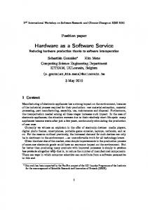
gent branches, is its simplicity: minimal number of elements (five tests and three output elements in our example: Fig. 4) and no need of the third type of element, the call of a subtree. The binary decision diagram can therefore lead directly to a hardware implementation (Fig. 6) with the following procedure: each test element (each diamond in Fig. 4) is implemented as a demultiplexer (DMUX) with a single control variable, which is the test variable; each information link between two elements of the diagram is implemented as a physical connection (a wire); each convergence of k arrows (representing a common subtree in the diagram) is implemented as an OR gate with k inputs; the input terminal in the logic diagram is given the value 1. The binary outputs labeled 30, 31 and F in Fig. 6 constitute the realization of the discrete function Z of the decoder in a 1-out-of-3 code. If the binary decision diagram is minimal for a given function 2 (i.e., has a minimal number of test elements), then the corresponding demultiplexer network will be minimal too, i.e., will have a minimal number of demultiplexers.
IEEE TRANSACTIONS ON EDUCATION. VOL. 36. NO. 1, FEBRUARY 1993
B. Other Hardware Applications
Any sequential system can be described by a state table, in which the next state Y + and the output state 2 are functions of the input state X and the present state Y . Implementing a sequential system is therefore reduced to finding a minimal binary tree (or diagram) of the discrete function Y + , 2 which depends on the X and Y variables. The main problem remains the simplification and the possible decomposition of the canonical tree. An example of a reversible counter is detailed in [5] and [20], while an exhaustive study of finite state machines can be found in [20]. A general method for synthesizing hardware systems by means of binary decision trees can be summarized as follows: starting with a Karnaugh map (for combinational systems) or with a state table (sequential systems), simplification and/or decomposition produces a tree with or without reconvergent branches, representing a discrete function 2 equivalent to n boolean functions 2,. . . . 21. One single demultiplexer tree with OR gates (and, in the case of a sequential circuit, with flipflops) implements the original specification; it can be shown that a network with n multiplexer trees (with flip-flops in the case of a sequential circuit) can constitute an equivalent system [20]. In conclusion, the method of binary decision trees and diagrams can easily and regularly be used in all hardware designs. The only limitation for hand calculation, due to the use of Karnaugh maps, is the number of input variables.
V. SOFTWAREIMPLEMENTATION A. Structured Programming The main advantage of a decomposition of a tree into a main tree and several subtrees is that this preserves the structure of trees which, in contrast to decision diagrams with convergent branches, meet the requirements of structured programming. Let us remember the definition of a structured program: the output instruction do s, characterized by an action s and having one input terminal connected to the preceding instruction and one output terminal connected to the next instruction, is a structured program. If P and Q are structured programs then the sequence of P and Q (do PQ) is a structured program; the iteration of P (while a do P ) is a structured program; the test giving P or Q (if a then P else Q) is a structured program; and all existing structured programs are those which can be obtained by applying definitions a) through d ) a finite number of times.
155
MICROPASCAL
ADR
program P P if M4 call sp else if M3 call s p else if MO do 31 else if M2
00 01 02
03
04 05 06 07 08 09
do 30
OA
OB
else do F
K
&dif endif endif endif procedure s p if MO do 30 else do 31 endif end procedure end program
10 11 12 13
14
U PROGRAM p p IF M4 ELSE 03 CALL 10 GO TO OD IF M3 ELSE 06 CALL 10 GOT0 OD IF MO ELSE 09 DO 31
GO TO OD IF M2 ELSE OC DO 30 GO TO OD DO F ENDIF ENDIF ENDIF ENDIF PROCEDURE sp IF MO ELSE 13
Do30 G O TO 14 DO 31 ENDIF RET END PROGRAM
Fig. 7. Software implementation in MICROPASCAL and L4 structured languages (ADR: present address).
B. Structuring and Interpreting Binary Decision Trees Binafy decision trees, unlike decision diagrams, can be directly implemented in a structured program (Fig. 7). This program, first expressed in a high-level language called MICROPASCAL, a minimal subset of PASCAL [ 5 ] , is derived from the decomposition of trees (Fig. 3) as follows: the main tree is implemented as the main program p p , beginning with the keyword program and terminating with end program; the subtree sp is realized as a single procedure sp, starting with the keyword procedure.. and terminating with end
...
.
procedure; each test element of the trees (a diamond in Fig. 3) is implemented as an if.. .else.. .endif structure; each output element (a rectangle) is implemented as a d o . . instruction, while each call of subtree element (a rectangle with four vertical bars) is implemented as a call.. instruction. A straightforward compilation, by hand or by computer, transforms the MICROPASCAL program in an equivalent lowlevel language L4 program (Fig. 7). This language is also structured, and is implemented by a set of four instructions only:
a) DO s GO TO ADR+1 b) IF a THEN A D R + l ELSE ADRO with the special case when a = 0: GO TO ADRO c) CALL ADSP RET TO ADR+1 d) RET
.
.
(action); (test), (unconditional jump); (procedure call); (return from procedure)
f
1
IEEE TRANSACTIONS ON EDUCATION. VOL. 36, NO. 1, FEBRUARY 1993
I56
where ADR is the actual address, ADRO and ADSP next addresses. The keywords PROGRAM.. , ENDIF, PROCEDURE.. and END PROGRAM are merely comments, without any address. If the decomposition of binary trees is minimal (i.e., has a minimal number of test elements), then the high-level language MICROPASCAL program and the low-level language L4 program will be minimal too, i.e., will have a minimal number of test structures (if.. .else. .endif or IF.. .ELSE.. .GO
.
.
2) Binary Decision Trees:
Definition, simplification, and decomposition of binary trees using Karnaugh map; Hardware implementation: demultiplexer/multiplexer network; Software implementation: definition of language L1 consisting of two types of instructions {IF a THEN ADRl ELSE ADRO} and {DOS GO TO A D R t } ; Interpretation of language L1 by means of a hardware interpreter: a binary decision machine; Application: comparator of two 4-bit numbers.
TO.. .ENDIF). The L4 program of Fig. 7 can be directly interpreted by a simple sequential machine, a binary decision machine, which has been described elsewhere [5]; this machine is built from classical bit-slice integrated circuits (controller or sequencer) or directly obtained as a single circuit with an UV-erasable and reprogrammable memory (for example: CMOS fieldprogrammable controller from Advanced Micro Devices).
. i
3) Subprograms, Procedures, and Stack Machine: Definition of subprograms, procedures, and nested procedures; Software implementation of procedures: language L2 with four types of instructions {IF a THEN ADRl ELSE ADRO, DO s GO TO A D R t , CALL ADSP RET TO ADRT, RET}; Interpretation of language L2 by a hardware interpreter: a binary decision machine with a stack; Procedure call with parameter passing; Applications: counter modulo-n, decomposition of counters, iterative combinational system (an adder).
VI. CONCLUSION A. Advantages and Drawbacks
The main advantage of the proposed approach is its universality: minimizing binary decision trees or diagrams produces minimal hardware circuits (i.e., multiplexer or demultiplexer networks with a minimal number of components) or minimal program (i.e., programs with a minimal number of IF THEN...ELSE instructions); this approach is a powerful tool for designing both hardware and software. On the hardware side, the increasing use of field programmable gate arrays (FPGA) based upon one- or twovariable multiplexer (e.g., the ACTEL family) makes our approach particularly attractive; the only drawback is the delay: in the worst case (a branch of the tree without any simplification), the signal must go through n circuits (multiplexer or demultiplexer) for n input variables, instead of the two levels for classical AND-OR networks. On the software side, the use of binary decision machines built from actual integrated circuits becomes more and more popular for the design of real time and medium scale programs (approx. 500 instructions). The binary decision treeidiagram is a tool for obtaining shorter programs and for introducing a true methodology in software design.
...
...
4) Incremental Programs and Controller:
.Definition of incremental programs; Software implementation with a modified version of language L2: L3 = {IF a THEN A D R t 1 ELSE ADRO, DO s GO TO A D R + l , CALL ADSP GO TO ADR+1,
RET); Interpretation of L3 by a stack machine built of an industrial controller; Application: digital clock. 5) Structured Programming:
Definition of the four constructions of structure programming; Syntactic definition of two structured languages: a highlevel language MICROPASCAL with 11 instruction types, a low-level language U,which is equivalent to L3 augmented of several keywords; Realization of a classical state table with minimal coding: software implementation based on a single tree and described by a structured MICROPASCAL or L4 program; Realization of a classical state table with one-out-of-n coding: software implementation based on 71 trees (one tree for each state) and described by a unstructured L3 program; Applications: reversible counter, car starter; Conclusion: methods for structuring unstructured programs.
B. Organization of the Course The first part of the new course Introduction to firmware theory is quite standard: it is devoted to the classical switching theory and to the analysis and synthesis of logic systems, both combinational and sequential (11 sessions of four hours each, whose one is dedicated to the lecture, the three other being devoted to laboratory experiments). The second part, which is the subject of this paper, comprises seven sessions of four hours each (one hour of lecture and three hours of laboratory) as follows: 1) Memories:
Definition and functional analysis of ROM and RAM; RAM with 3-state circuits and hi-directional buses; Realization of a classical state machine with RAM.
6) Top-Down Programming: 9
Method of successive refinements; Case study: the clock algorithm, for a complex digital watch;
1
IEEE TRANSACTIONS ON EDUCATION, VOL. 36, NO. 1, FEBRUARY 1993
First implementation with a complex program and a simple processing unit (software dominant solution); Second implementation with a simple program and a complex processing unit (hardware dominant solution).
157
REFERENCES [ l ] P. W. Samaras, “Integrating the first two years,”ASEE Prism, pp. 16- 19, Nov. 1991. [2] E. Cerny, D. Mange, and E. Sanchez, “Synthesis of minimal binary decision trees.” IEEE Trans. Comout., vol. C-28. no. 7. DO. 472-482, July 1979. [3] E. Sanchez and A. Thayse, “Implementation and transformation of algorithms based on automata, Part 111,” Philips J . Res., vol. 36, no. 3, pp. 159-172, 1981. [4] A. Thayse, “Synthesis and optimization of programs by means of Pfunctions,” IEEE Trans. Comput., vol. C-31, no. 1, pp. 34-40, Jan. 1982. [5] D. A. Mange, A high-level-language programmable controller, Parts I11, IEEE Micro, vol. 6, no. 1, pp. 25-41, Feb. 1986; no. 2, vol. 6, pp. 47-63, Apr. 1986. [6] S. B. Akers, Bi& decision diagrams, IEEE Trans. Comput., vol. C-27, no. 6, pp. 509-516, June 1978. (71 B. M. E. Moret, Decision trees and diagrams, Computing Surveys, vol. 14, no. 4, pp. 593-623, Dec. 1982. [8] R. E. Bryant, “Graph-based algorithms for boolean function manipulation, IEEE Trans. Comput., vol. C-35, no. 8, pp. 677-691, Aug. 1986. [9] C. Y. Lee, Representation of switching circuits by binary-decision programs, TheBellSyst. Tech.J., vol. 38, no. 4, pp. 985-999, July 1959. (101 C. R. Clare, Designing Logic Systems Using State Machines. New York: McGraw-Hill, 1973. [11] R.T. Boute, The binary decision machine as programmable controller, Euromicro Newsletter, vol. 2, no. 1, pp. 16-22, Jan. 1976. (121 W.1. Fletcher, An Engineering Approach to Digital Design. NJ: Prentice-Hall, Englewood Cliffs, 1980. [13] M. Andrews, Principles of Firmware Engineering in Microprogram Control. London: Pitman, 1981. [ 141 P. J. A. Zsombor-Murray, L. J. Vroomen, R. D. Hudson, T. Le-Ngoc, and P. H. Holck, “Binary-decision-based programmable controllers,” Parts I111, IEEE Micro, vol. 3, no. 4, pp. 67-83, Aug. 1983; vol. 3, no. 5 , pp. 16-26, Oct. 1983; vol. 3, no. 6, pp. 24-39, Dec. 1983. [15] M.,Davio, J.-P. Deschamps, and A. Thayse, Digital Systems with Algorithm Implementation. Chichester: John Wiley, 1983. [16] L.D. Coraor, P.T. Hulina, and O.A. Morean, “A general model for memory-based finite-state machines,” IEEE Trans. Comput., vol. C-36, no. 2, pp. 175-184, Feb. 1987. [17] A. Ginetti and C. Trullemans, “Compaction of CD ( 2 k - D ) control unit architectures,” Integration, VLSI J., vol. 9, pp. 179- 197, 1990. [18] C. Piguet, “Binary-decision and RISC-like machines for semicustom design,” Microproc., Microsyst., vol. 14, no. 4, pp. 231 -239, May 1990. [ 191 D. Mange, Systemes microprogrammes: une introduction au magiciel. Lausanne: Presses polytechniques et universitaires romandes, 1990. [20] -, “Microprogrammed Systems: An Introduction to Firmware Theory. London: Chapman & Hall, 1992. [21] P. Grogono, Programming in PASCAL. Reading, MA: Addison-Wesley, 1984. ,
7) Microprogramming a Universal Processor:
Analysis of an arithmetical and logic unit with registers (RALU); Getting a universal processor by the assemblage of a binary decision machine with a stack (control unit) and a RALU (processing unit); Case study: microprogramming the multiplication of two binary numbers; Further application (for advanced students): microprogramming the compilation of MICROPASCAL highlevel language into L4 low-level language. Our course is followed in the three next years by more specialized lectures on hardware (microprocessors, computer architecture, etc.): it must be pointed out that students are taught during the first year a classical course about procedural programming (PASCAL) during 15 sessions of three hours each and based upon reference [21]. C. Related Works Binary decision trees have become more and more popular, especially for analyzing and testing logic circuits [6]-[SI. Programming a binary decision machine and using it to replace hardwired logic systems or classical microprocessors is less popular; nevertheless, after the historical publications of Lee [9], Clare [lo] and Boute [ l l ] , a number of researchers in the United States and overseas have paid great attention to this new methology and/or have realized VLSI binary decision machines: W. I. Fletcher, Utah State University, Logan 1121 (pp. 600-645); M. Andrews, Colorado State University [13] (pp. 210274); P. J. A. Zsombor-Murray et al., McGill University, Montreal, Canada [14]; M. Davio et al., Philips Research Laboratory, Brussels and UniversitC Catholique de Louvain, Belgium [15]; L. D. Coraor et al., Pennsylvania State University, University Park [16]; A. Ginetti, C. Trullemans, UniversitC Catholique de Louvain, Belgium [17]; C. Piguet, Centre suisse d’ilectronique et de microtechnique, Neuchltel, Switzerland [18]. The course described in this paper is based on the book [19], in French, which was recently published in English [ZO]; significant extracts of the latter can be found in [5].
..
Daniel Mange (S’68-M’69) received the M.S. and Ph.D. degrees from the Swiss Federal Institute of Technology, Lausanne, Switzerland. Since 1969, he has been a Professor at the Swiss Federal Institute of Technology. He held a position as Visiting Professor at the Center for Reliable Computing, Stanford University, Stanford, CA, in 1987. He directs the Logic Systems Laboratory and is mostly interested in firmware theory (equivalence and transformation between hardwired systems and programs), cellular automata, and artificial life.