290
IEEE TRANSACTIONS ON EDUCATION, VOL. 48, NO. 2, MAY 2005
Teaching Reconfigurable Systems: Methods, Tools, Tutorials, and Projects Valery Sklyarov and Iouliia Skliarova
Abstract—This paper presents an approach that has been used for teaching disciplines on reconfigurable computing and advanced digital systems, which are intended to cover such topics as architectures and capabilities of field-programmable logic devices; languages for the specification, modeling, and synthesis of digital systems; design methods; computer-aided design tools; reconfiguration techniques; and practical applications. To assist the educational process, the following units have been developed and employed in the pedagogical practice: animated tutorials, miniprojects, hardware templates, and course-oriented library of digital circuits. To stimulate the student’s activity, an optional project-based evaluation technique has been applied. All the materials that are required for students are available on the university website (WebCT) and can easily be used for studying inside the university, for obtaining additional information during practical classes and for distance learning. Index Terms—Animated tutorials, educational technology, fieldprogrammable gate array (FPGA), miniprojects, reconfigurable architectures, reconfigurable computing.
I. INTRODUCTION
W
ITH the advent of field-programmable logic devices, one became able to design and implement digital systems without the need for the technological steps dealing with silicon. Tremendous progress in this area has made it possible to advance configurable microchips from simple gate arrays that appeared on the market during the mid-1980s [1] to platform field-programmable gate arrays (FPGAs) containing more than 10 million system gates and incorporating complex heterogeneous structures, such as PowerPC processors. For example, an XC2VP100 FPGA of the Xilinx Virtex-II Pro family [2] integrates on a single chip two PowerPC processor blocks, 444 multiplier blocks (18 18 b each), 444 RAM blocks (18 Kb each), multigigabit transceivers, 99 216 reprogrammable logic cells, and many other components. Such incredible evolution in FPGAs, which were first introduced by Xilinx, Inc., San Jose, CA, in 1985, has required less than 20 years. The plenary talk by Butts in FPL [3] reports that future project densities are likely to be upwards of 100 billion devices per square centimeter and argues that cheap molecular-scale reconfigurable logic, memory, and interconnect are likely to become the predominant digital technology a decade hence.
Manuscript received March 11, 2004; revised September 21, 2004. This work was supported in part by the Portuguese Foundation of Science and Technology under Grant POSI/43140/CHS/2001. The authors are with the Department of Electronics and Telecommunications and Instituto de Engenharia Electrónica e Telemática de Aveiro (IEETA), University of Aveiro, 3810-193 Aveiro, Portugal (e-mail:
[email protected];
[email protected]). Digital Object Identifier 10.1109/TE.2004.842909
The impact of FPGAs on different development directions in electrical and computer engineering is growing continuously. When FPGAs were first introduced, they were predominantly used for implementing simple random and glue logic [1]. Nowadays, even undergraduate students are capable of constructing quite complex digital devices on a single FPGA chip. Today, advanced research is being intensively performed in the areas of system on chip (SoC) and networks on chip (NoC) [4]. The importance of reconfigurable systems is evidenced by the annual expansion of the FPGA market and the increased attention that this topic now receives at top-level technical conferences, such as the Design Automation Conference and the Design, Automation and Test in Europe. Developing digital systems on the basis of high-capacity FPGAs requires the use of computer-aided design (CAD) tools. In fact, the electronic design automation business has profoundly influenced the integrated circuit business, and vice versa, e.g., in the scope of design methodology, verification, libraries, and intellectual property (IP) [5]. Traditionally, FPGA-targeted CAD systems support schematic and hardware description language (HDL)-based design flows involving model-specific tools (such as the synthesis of finite-state machines (FSM) from a graphical specification) and IP core generators based on parameterization or templates. Recently, commercial CAD tools allowing digital circuits to be synthesized from system-level specification languages (such as Handel-C [6] and SystemC [7]) have appeared on the market. In this area, C and C++ with class libraries are emerging as the dominant languages in which system descriptions are provided [5]. Thus, the domain of reconfigurable systems design is very dynamic and many-sided. The rapid evolution of FPGA technology and CAD tools for reconfigurable systems requires a large number of well-prepared engineers in the relevant areas. Thus, new trends must be reflected in the respective pedagogical activity. An ongoing review of the corresponding curricula is necessary in order to incorporate the recent advances in FPGA architectures, design methods, and CAD tools. In other words, the curriculum must be sensitive to changes in technology and new developments in pedagogy and should emphasize the importance of lifelong learning [8], [9]. This paper describes a methodology that has been used for teaching reconfigurable systems at the Department of Electronics and Telecommunications of the University of Aveiro, Aveiro, Portugal. In 1997, the first optional discipline in this area entitled advanced digital systems was introduced. Today three disciplines are included in the pedagogical plans: reconfigurable computing (RC), reconfigurable digital systems (RDS), and advanced reconfigurable systems (ARS).
0018-9359/$20.00 © 2005 IEEE
SKLYAROV AND SKLIAROVA: TEACHING RECONFIGURABLE SYSTEMS
291
The remainder of the paper is organized in six sections. Section II presents a reconfigurable system course overview. Section III discusses methods and tools that have been used for teaching. Section IV describes the developed animated tutorials with examples. Section V suggests one possible type of student’s evaluation through miniprojects. Section VI illustrates the structure of the university website (WebCT [10]), which accumulates all the available additional materials for the group of disciplines considered. The conclusion is given in Section VII.
II. RECONFIGURABLE SYSTEM COURSES OVERVIEW The disciplines on reconfigurable computing are offered to the fourth- and to the fifth-year students of two undergraduate curricula: LECT—Computer Engineering and LEET—Electronics and Telecommunications Engineering. The following core set of courses given to students of both curricula before the fourth year provides the required foundation: •
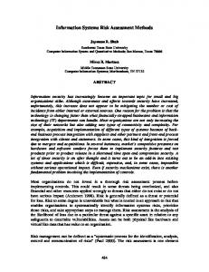
software engineering, in particular, the students have a good knowledge in C/C++ programming languages; • electronics; • digital systems; • signal and systems and digital signal processing; • computer architecture; • interfaces and peripheral devices (which is more common for the LEET curriculum). Until the 2003–2004 academic year, the students acquired very little experience in HDL during the first three years of study (limited to just some elementary advanced Boolean equation language (ABEL) constructs). Starting from the second semester of 2003–2004, a small subset of very high speed integrated circuit HDL (VHDL) has been taught within the digital systems discipline using LogicWorks software [11] for simulation. Since nowadays HDL-based design flow is the basic strategy for developing reconfigurable systems, the relevant topics must be covered in detail. Historically, the group of disciplines on reconfigurable systems holds the major responsibility for this direction at the Department of Electronics and Telecommunications of the University of Aveiro. Another issue that should be addressed is the relationship between HDL and system-level specification languages (SLSLs). On the one hand, HDL-based design flow keeps the students closer to specific features of hardware development, a very important issue. On the other hand, SLSLs, such as Handel-C and SystemC, permit the design time to be shortened significantly, and they are very promising for future systems [5]. Taking into account all these issues, the set of topics shown in Fig. 1 has been proposed. Basically, two successive stages of expertise cover HDL- and SLSL-based design flows. These stages make possible the compromise between the lower and higher levels of abstraction for hardware specification to be established. The first stage is provided by the disciplines RC for LECT and RDS for LEET. The right-hand column of Fig. 1 shows general topics that are studied, and the left-hand column presents some additional details, mainly about the particular hardware/software components and systems that have been used. References in square brackets point to the recommended additional materials.
Fig. 1. Set of topics considered within the group of courses on reconfigurable systems design.
The first stage provides the base for the second stage and covers the following five directions. 1) There is an introduction to programmable logic design, which includes history, complex programmable logic devices (CPLD) and FPGA architectures, design flow, CAD tools, practical applications, and prototyping boards. 2) Another direction is the VHDL-based design flow. VHDL was chosen as the primary HDL for reasons reported in [16]. Since the time available for this topic is limited, the emphasis is on a synthesizable VHDL subset. The Xilinx’s integrated software environment (ISE) [2] is studied as an example. Note that a substantial difference exists between general-purpose programming languages, such as C/C++, and HDL, which must be properly understood for hardware design. This issue is a key point, which is addressed within the considered group of disciplines. Generally, the teaching methodology that has been adopted has a number of features in common with [16] and [17]. 3) CAD tools are studied by applying them to an example of the well-known industrial system ISE from Xilinx. Currently, version 6.2.02 is used, but it is periodically updated as soon as a new version is launched. Besides the commercial version, Xilinx also supplies a freeware Web PACK [2]. This freeware is very important for students and makes it possible for them to work either inside or outside of the university. Simulation, indispensable for hardware design, is carried out with the aid of the STARTER version of ModelSIM [18]. When necessary to model a digital system at a higher level of abstraction, the C++ language is used. The following design tools of ISE are currently involved:
292
IEEE TRANSACTIONS ON EDUCATION, VOL. 48, NO. 2, MAY 2005
Fig. 2. Course-oriented tools and applications.
top-level schematic designs, top-level VHDL designs, functional and timing simulation, libraries and VHDL templates, StateCAD for the design of FSMs, and IP core generator. 4) Reconfiguration (both static and dynamic) and hardware templates are covered. Different types of dynamic reconfiguration have been exemplified, such as those available for the Virtex FPGA family, context switching, and reloading embedded RAM blocks. Special attention was given to the use of hardware templates [19], which are circuits with a predefined structure implemented in hardware (in FPGA, in particular). The basic components of the circuit are RAM blocks, and by reprogramming these, one can provide for a different functionality. Hardware templates for reprogrammable FSMs [19], [20] and accelerators for operations over discrete vectors [14] have been considered in detail. 5) Practical applications are divided into two groups: simple circuits that have to be designed during laboratory work and more complicated miniprojects that are used for the final evaluation (see Section V for details). Examples of circuits from the first group are simple processing units, blocks providing interfaces with peripheral devices, and external microchips (such as a touch panel and a liquid-crystal display (LCD) microcontroller), etc. The majority of these circuits are well covered by the relevant tutorials, and they will be discussed in Section IV. The ARS discipline in the second stage is based on the material of the first stage and is devoted to system-level specification languages for hardware design. Two such languages, SystemC [7] and Handel-C [6], are discussed. SystemC is a library that permits hardware components to be modeled using a standard C++ compiler. Since the department does not have software tools that permit FPGA-based circuits to be synthesized from a SystemC specification, this language
(library) is just considered at a description level. On the other hand, the Handel-C language and the DK2 design suite of Celoxica [6] are used for the design and implementation of digital systems based on FPGAs. Handel-C permits digital circuits to be described in a C-based style and to be modeled, debugged, and synthesized using development tools supplied by Celoxica [6]. The result of synthesis is an electronic design interchange format (EDIF) file that can be used for mapping, placement, routing, and the generation of FPGA bit streams with the aid of commercially available CAD systems, such as Xilinx ISE 6.2 [2]. At the final step, the generated bit stream is loaded into the target FPGA. Alternatively, a Handel-C specification can be converted to a synthesizable VHDL code, which can be used in a CAD environment (such as Xilinx ISE 6.2 [2]) for constructing library components. Thus, these components can be reused, either in Handel-C (i.e., in an EDIF-based flow) or as VHDL library modules within other commercially available CAD systems. Celoxica’s platform development kit (PDK) is an integrated library offering three layers of functionality: these are the platform support library (containing a set of drivers for different prototyping boards), the platform abstraction layer (delivering low-level hardware interfaces between the FPGA/CPLD and external logic), and the data stream manager (providing integration components and methods that allow the implementation of system designs split across processors and FPGA/CPLDs to be simplified). These tools have also been used in the educational process. As one can see from Fig. 2, the basis for any discipline from the group considered consists of four primary directions with which the students are working: 1) prototyping, 2) design flow, 3) interface, and 4) applications. The left-hand part of Fig. 2 lists the FPGA-based prototyping boards that have been used for both laboratory work and miniprojects since 1997. Experience has shown that a diversity of boards does not give rise to
SKLYAROV AND SKLIAROVA: TEACHING RECONFIGURABLE SYSTEMS
any problem. On the contrary, it enables the students to appreciate that each CAD system must be configured for the particular FPGA microchip being used, taking into account such characteristics as the number of pins and speed grade. At present, the following boards (containing FPGAs recommended for future applications) are being used. • Trenz Electronic TE-XC2Se [21], which is the principal prototyping board for the RC and RDS laboratory works. Different boards contain either an XC2S300E Spartan-IIE FPGA with 300 000 system gates or an XC2S400E Spartan-IIE FPGA with 400 000 system gates. According to [21], the resources provided by the XC2S300E FPGA are sufficient for constructing two and a half of 8051 microcontrollers so that quite complicated circuits can be implemented. The board also contains 256 K 16 b static RAM, 1 MB flash RAM, LCD (two lines 16 characters), eight dip-switches, pushbuttons, and light-emitting diodes (LEDs). It can be connected to a VGA monitor, supports USB and RS-232 serial interfaces, and has two expansion headers. Power is supplied through USB, and no additional source is required. • Celoxica RC100 [6] with an XC2S200 Spartan-II FPGA (200 000 system gates), which is the primary prototyping board for the ARS laboratories. The board also contains two blocks of static RAM (256 K 36 b each), 64 Mb flash RAM, two eight-segment displays, and two LEDs. It provides control of a VGA monitor, a keyboard, a mouse, and video in/out and supports a parallel interface. PDK of Celoxica [6] contains all the necessary drivers and support tools for communications with all the peripheral devices mentioned previously. • XESS XSA100 [22] with an XC2S100 Spartan-II FPGA (100 000 system gates) is additionally used for the RC and RDS laboratories. Detailed description of all the boards mentioned previously can be found in [12] with many ISE design examples.1 • Expert version of the Celoxica RC200 prototyping system [6] with an XC2V1000 Virtex-II FPGA (1 000 000 system gates), which is used for the ARS miniprojects and for final-year projects. The board also contains two blocks of static RAM that are 4 MB each, a 16-MB smart media card, a bluetooth wireless module, a touch-screen display, an Ethernet socket, two seven-segment displays, switches, and LEDs. It provides control of a keyboard, a mouse, video in/out, a color camera, a headphone/microphone set, and parallel and RS-232 interfaces. PDK of Celoxica [6] contains the necessary drivers and support tools for communications with all the peripheral devices mentioned previously. • Alpha Data ADM-XPL PCI board [23] with an XC2VP7 Virtex-II Pro FPGA, which is used primarily for finalyear projects and Ph.D. students. However, this board 1Since November 2004, all of the materials can be accessed through the following address: http://elearning.ua.pt. All the required details can be provided via e-mail:
[email protected];
[email protected]
293
also helps to demonstrate the capabilities of a platform FPGA for students attending all the disciplines considered (Fig. 1). Note that this board (used at the department) is the only one that interfaces with a host computer through a PCI bus. This arrangement allows for the development of very high speed hardware accelerators. In the majority of practical applications, FPGA-based circuits have to exchange data with external devices, such as memories, displays, microprocessors, and other FPGAs. Thus, the appropriate interfaces need to be developed, which require an understanding of how to configure FPGA input/output (I/O) blocks to support the appropriate I/O standards, how to establish synchronization mechanisms between an FPGA and external devices, how to build I/O buffers, etc. Three groups of interfaces (Fig. 2) have been studied. They are widely used standard protocols, such as RS-232, Universal Serial Bus (USB), etc.; Peripheral Component Interconnect (PCI); and those that provide interactions between the FPGA and external microchips, such as static memory, LCD controllers, and microprocessors. The majority of the interfaces considered are supported by the respective components available on the prototyping boards. For HDL-based design flow, a set of language templates has been developed. These templates are discussed in more detail in Section III. For Handel-C design flow, the PDK of Celoxica [6] provides all the required support. The last item that is addressed is applications (Fig. 2). At present, applications are divided into the following seven groups, which are updated periodically. 1) The first group consists of calculators and processors, which either implement a reduced set of instructions or execute nontypical operations, such as those required for the processing of discrete matrices [24]. 2) The second group consists of hardware/software (HW/SW) co-simulation [25]. For many practical problems, the communication between relatively autonomous subsystems must be examined to assess the characteristics of the system, such as the correctness of the functionality, the adequacy of the performance, and the accuracy of execution. Note that this assessment has to be made before all the components of the system have been implemented. The idea is to create a model that is partially implemented in software and partially in hardware, communicating through a preestablished interface [25]. Many models of this type have been proposed to the students. One example is given in [12] and [25], where a virtual plotter controlled by an FPGA is described (see also Section V). Such projects require experience in the development of both reconfigurable hardware and general-purpose software. 3) The third category is digital systems that enable the students to execute combinatorial search algorithms such as those that make the solution of the covering problem possible [26]. For example, in 2003, one student project from this area, which is available at [12], was implemented on the basis of the Alpha Data PCI board with a Virtex-II Pro family FPGA.
294
IEEE TRANSACTIONS ON EDUCATION, VOL. 48, NO. 2, MAY 2005
4) This category consists of circuits that provide recursive computations, such as [27]. Examples of such computations are recursive traversal of a binary tree for data sorting, discovering the greatest common divisor, etc. 5) Electronic games comprise the fourth category. 6) Another category consists of hardware implementation of data compression/decompression algorithms (see the Internet site [28], which collects many useful publications, methods, and tools). The results of one student project from this scope can be found in [12]. 7) The last category is hardware accelerators [14] which make it possible to speed up various operations required for application-specific computations. The majority of student miniprojects were done in this area (student publications are available at [12]). III. METHODS AND TOOLS The previous section shows that the material of the group of disciplines considered includes not only topics directly targeted at reconfigurable systems design, but also some supplementary themes to compensate for the lack of the required background. Therefore, the integration of a large amount of material is required within the course. First, the students have to acquire experience in using HDL. Insufficient training in HDL for undergraduate students was also reported in [16], based on the results of a survey analyzing responses from 71 U.S. universities. To cope with this problem, instructors need to provide more intensive learning techniques that allow more knowledge to be dispersed within the same time slot. This task has been achieved through the systematic use of well-organized auxiliary materials, namely, tutorials, design templates, and previously accumulated students’ experiences. The following methods and tools are employed. 1) A technique is used that assumes a separation of the designed circuits into core and secondary components. The core component enables the students to understand the major element that is going to be introduced and explained. Such an element might be an architecture, a method, an algorithm, a piece of HDL code, or something similar. The secondary components allow some aspects to be clarified or the core component to be tested. For example, they permit the following to be pursued: interaction with peripheral devices; detection of problems that might appear; testing the core component functionality; determination of what is allowed and what is not allowed, etc. 2) A set of templates for secondary components are used. As a rule, a template is a piece of VHDL code that can be inserted into any project to supply the auxiliary opportunities considered previously. Much like synthesis templates for ISE enable the designer to shorten the circuit development time, the proposed templates enable the students to concentrate on the major issues and to extract these from other things that are less important. Experience has shown that such a method allows the time required for understanding a given topic to be
3)
4)
5)
6)
7)
8)
reduced. For example, tutorial 5 from [12] demonstrates how to use various VHDL constructions in ISE that can be synthesized and supplies code for testing any construction on a prototyping board with the possibility for entering initial data and visualizing the results. Other tools employed are course-oriented design tools and libraries [29], which permit more practical and complex miniprojects to be implemented within a given time slot. This implementation can be accomplished because a significant part of the circuit to be developed can be constructed from predefined components, leaving the remaining (core) part needs to be designed. Animated tutorials that cover the most important topics of the course are employed. These are very helpful, especially at the beginning stage where many unusual issues must be understood. Also implemented is an evolutionary technique where current student projects are based on the previously developed student projects that are well documented and available for the future. Thus, specific requirements have to be established for the projects to make their repeated reuse straightforward. Another method is the provision of an opportunity to publish the best student projects in the department magazine. Experience has shown that this activity stimulates students significantly. Of course, each paper has to be carefully checked and edited by teaching staff, taking considerable time and effort, but the results of such activity are very remarkable. Many student papers have been published [12], and these are very helpful to future students. There are examples when a student was unable to complete the paper during the course. However, he/she continued to work and presented the paper later (six to twelve months later), i.e., after completing the course and passing the exam. Another method is the establishment of collaboration with other disciplines. Note that miniprojects cover quite a broad scope of potential applications (Fig. 2). Many of them may be needed for projects that have to be completed outside of the course. If necessary, specifications of some miniprojects can be adapted to other requirements and constraints. Thus, the collaboration with other disciplines becomes natural. The group of disciplines relating to reconfigurable digital systems teaches methods and tools; other department groups might offer applications. This approach provides an additional motivation for the students because reconfigurable systems can be linked with a similar work within other disciplines, in which particular students may be very interested. This type of collaboration has already been established, primarily in the scope of embedded system design and also in the telecommunications area. Also used is one of the two following acceptable kinds of final evaluation: 1) through a traditional exam at the end of the course and 2) through individual miniprojects (see Section V). Experience has shown that the first kind has been chosen by the students in only a few cases.
SKLYAROV AND SKLIAROVA: TEACHING RECONFIGURABLE SYSTEMS
295
The majority of the students prefer the second option independent of the following established requirements. To be able to select an individual miniproject, the student must attend all the practical and theoretical classes. Every absence is taken into account except where an acceptable justification document has been presented. Experience has shown that 90%–95% of the students have attended all the classes. 9) Finally, WebCT [12] is used as a central storage where all the materials are available to be used both inside and outside of the university (see Section VI for details). Fig. 3.
Possible examination of VHDL constructions in tutorial 5 [12].
IV. TUTORIALS The existing tutorials and those that are going to be created can be divided into the following four groups. 1) The first are tutorials that demonstrate various scenarios within the respective CAD environment and explain the use of the prototyping boards. For example, the tutorials 1–4 and 6 [12] show how to create a simple design in ISE, how to work with different tools (namely, VHDL, schematic and constraints editors, simulators, StateCAD, libraries, and IP core generator), how to build a bit stream, and test the design in the TE-XC2Se prototyping board, etc. 2) Tutorials that explain language constructions that can be synthesized and their distinctive features are also used. For example, tutorial 5 [12] describes a subset of VHDL that can be synthesized for ISE [2] with the aid of examples that are ready to be tested either in the ModelSim/ISE simulator or on a prototyping board. 3) There are tutorials that illustrate different modes of interaction with typical peripheral devices through widely used interfaces. For example, tutorial 7 [12] demonstrates various possible data exchange scenarios with the EA KIT240–7 of Electronic Assembly [30] through an RS-232 serial port. It permits data to be sent to a graphical screen with a resolution of 240 128 pixels and data to be read from a touch panel. Tutorial 9 [12] shows how to communicate with an LCD using an extended instruction set such as that implemented in the Samsung KS0073 Driver and Controller for a dot matrix LCD [30]. Using these tutorials enables the students to understand how to link the developed circuits with typical peripheral devices. The majority of VHDL code describing communication mechanisms can be copied from the tutorials and tested in a physical environment, or alternatively, can be inserted into the student projects in order to provide for data input and visualization of the results. 4) Tutorials that permit different design methods to be understood. For example, tutorial 8 [12] explains how to describe reprogrammable FSM in VHDL. The tutorial 10 shows how to construct a recursive hierarchical FSM and how to use this FSM for recursive data sorting. Tutorial 11 explains how to describe various recursive algorithms in Handel-C and presents projects that provide for
a solution to the knapsack combinatorial problem, data sorting, and discovering the greatest common divisor of two integers. All the tutorials are supported by relevant examples of ISE/DK2 projects that can be used to synthesize and to test the respective circuits based on the prototyping boards mentioned previously. Fragments of the projects can also be used by the students. The following subsections present some examples. A. Example 1 Fig. 3 illustrates a possible use of tutorial 5 [12] from group 2, and Fig. 4 shows a fragment from this tutorial. Different VHDL constructions that can be synthesized are explained through examples that can be tested either in a simulator, such as ModelSim [18], or in an FPGA. In both cases, the students can carry out experiments changing input values and verifying the results. Then, if necessary, various possible modifications of the VHDL code can also be examined. Any tutorial project contains fixed FPGA-based circuits (see the FPGA control block in Fig. 3) and a circuit synthesized from a VHDL specification that is to be analyzed (see the tested VHDL block in Fig. 3). The fixed circuits permit input data to be entered through physical devices (such as those shown in Fig. 3) and the result obtained from the designed circuit to be displayed. This procedure enables the students to check all feasible variations of the VHDL code in order to be sure that it has been understood correctly. Fig. 4 explains how to describe the structure of a circuit that is composed of two blocks: a clock divider and an FSM. Depending on the code from dip switches , , and , the FSM LED , generates different sequences on the outputs LED which are shown on the attached LEDs. The divider adjusts the clock frequency in such a way that all the successive changes in the results can be appreciated visually. The students are able to carry out different experiments with this circuit, such as varying the FSM specification, comparing the results with the outputs of a simulator, synthesizing the FSM from VHDL and from StateCAD, and adding new blocks to the structural specification. The bottom-left corner of each tutorial slide (Fig. 4) points to the relevant compressed ISE project. If necessary, a part of the VHDL code can be copied to student projects to shorten the development time. All the slides involve animation effects that make it easier to understand a sequence of operations that has to be performed or to exhibit the order in which the student should
296
IEEE TRANSACTIONS ON EDUCATION, VOL. 48, NO. 2, MAY 2005
Fig. 4. Example of a slide from tutorial 5 [12].
study the respective topics. Different major VHDL constructs or features in tutorial 5 [12] have been sorted alphabetically which, on the one hand, simplifies finding a particular item and, on the other hand, allows the tutorial to be considered as a VHDL reference guide. B. Example 2 Fig. 5 illustrates a fragment of tutorial 11 [12] from group 4. It demonstrates how to describe in Handel-C a recursive algorithm that traverses a binary tree in order to sort integers associated with the binary tree nodes. The left subtree of a node contains only values that are less than the value at the node, and the right subtree contains only values that are greater [Fig. 5(a)]. In order to sort the data, one can apply a special technique [31] using forward and backtrack propagation steps that are exactly the same for each node. Thus, a recursive procedure is very efficient. Fig. 5(b) depicts the algorithm for sorting described in the hierarchical graph-schemes language (HGS) [32]. The HGS module can call itself in the rectangular nodes and . The recursive control sequence that is required for the HGS in Fig. 5(b) can be generated by a hierarchical FSM (HFSM) [32]. The execution unit for this example is shown in Fig. 5(c) [27]. All the details illustrated through the relevant VHDL specifications are given in [27]; therefore, they will be skipped to concentrate on the organization of the tutorial. The HGS labels [Fig. 5(b)] are associated with the HFSM states [32]. Fig. 5(d) explains how to describe the recursive HFSM in Handel-C. There are two types of transitions. One allows new modules to be invoked [see a switch(module) statement in Fig. 5(d)], and the other allows the states of an active module to be changed [see a switch(state) statement in Fig. 5(d)]. These transitions are explained through animation effects, such as the
sequentially appearing arrow curves shown in Fig. 5. A student can execute the recursive algorithm in a virtual space, watching a sequence of simultaneously occurring events, such as forward in Fig. 5(a)] or backtrack [see arrow lines [see arrow lines in Fig. 5(a)] propagation steps; highlighting active nodes of the HGS [Fig. 5(b)]; forced data transfer in the execution unit [Fig. 5(c)], and active statements of Handel-C [Fig. 5(d)]. Such simultaneous changes leading to the final result of data sorting (such as , , , in Fig. 5) can be played in different modes (e.g., step back and step forward). Finally, the students are able to shorten significantly the time needed for understanding the relevant topics. V. MINIPROJECTS AND EVALUATION At the beginning of a semester, students can choose a miniproject option for the final evaluation, in which case, it will be used at the end of the semester instead of an exam. Some requirements agreed upon for each miniproject are 1) that it be individual, 2) that it involves the majority of methods and tools considered within the relevant discipline, and 3) it is complete and relatively complicated. The time available for each miniproject is 13 to 15 weeks. At the end of this period, the students have to be able to explain all the methods, language constructions, and automation tools invoked in the design. Fig. 6 demonstrates how the development process for miniprojects has been organized. The first step is to formulate and discuss the design problem with the student, usually requiring a few iterations. Up to the present time, the seven areas of feasible applications depicted in Fig. 2 have been considered. Obviously, they might be extended in the future. Examples of student projects can be found in [12]. After the student
SKLYAROV AND SKLIAROVA: TEACHING RECONFIGURABLE SYSTEMS
297
Fig. 5. Example of a slide from tutorial 11 [12].
Fig. 6. Using the tutorials [12] for the development of miniprojects.
understands the problem, he/she will begin the design with an opportunity to reuse the previously developed blocks, such as those available in the tutorials [12] of groups 3 and 4 (see the right-hand and bottom part of Fig. 6). On the other hand, the tutorials from the groups 1 and 2 [12] (see the left-hand
and top part of Fig. 6) provide a significant assistance in the design steps, design tools, and design languages. Finally, the development time can be shortened because students find that they can more easily (Fig. 6): 1) use the design tools, 2) use the hardware-targeted languages, 3) interact (i.e., provide data
298
exchange) with the designed circuit, and 4) use the design methods and the previously developed hardware blocks. The best student projects are recommended for publications in the department magazine. The following are some examples of such publications. • Handel-C project (see electronic games application in Fig. 2) for a gap puzzle, which can be tested in the Celoxica RC100 prototyping board [6] with connected mouse, keyboard, and VGA monitor: This configuration permits a graphical picture that is initially kept in a flash memory to be copied to a static RAM available on the board for future processing. The picture is divided into a rectangular array of squares that are swapped arbitrarily. The task is to reconstruct the correct image on the monitor screen by moving the squares to their correct positions. This task can be accomplished by using the mouse and the keyboard. • HDL-based project (see application HW/SW co-simulation in Fig. 2) for a virtual simulation of plotter functionality: Electromechanical plotter units are displayed on a monitor screen of a personal computer, and the general-purpose software that is developed in Visual C++ permits various manipulations and movements of these units to be shown on the screen imitating the plotter functionality. The virtual plotter is controlled by FPGA-based circuits developed on the XS40 prototyping board communicating with the personal computer through a parallel port. • Handel-C project (see the application data compression/decompression in Fig. 2) for the Celoxica RC200 prototyping board devoted to transferring high-volume data to an FPGA: In order to reduce the communication time, a compression/decompression technique is employed in such a way that the host computer compresses data and transfers them to an FPGA and the FPGA decompresses them using algorithms based on a slightly modified version of the Huffman method. • HDL-based project (see calculators and processors application in Fig. 2) for an FPGA-based calculator interacting with a touch panel (EA KIT240-7) of Electronic Assembly [30] connected to the FPGA: The circuit can be tested in the prototyping board TE-XC2Se of Trenz Electronic [21]. • HDL-based projects (see hardware accelerators application in Fig. 2) for dynamically reconfigurable hardware accelerators executing operations over Boolean and ternary vectors: Each project includes a software part that is implemented in C++ programs running on a host computer and a hardware part that is realized on the XS40 prototyping board linked to the host computer through a parallel port. The FPGA circuit is composed of the following four primary components: an interface with the host computer, a set of control units that are reprogrammable from the host computer, an execution unit, and a reconfiguration handler that provides the required dynamic modifications to the FPGA circuit functionality.
IEEE TRANSACTIONS ON EDUCATION, VOL. 48, NO. 2, MAY 2005
The majority of the projects and all the student papers referenced here are available online at [12]. VI. WEBCT To maximize the effectiveness of the classes, students have access to all the required materials through a central point that is the WebCT [10], [12]. Fig. 7 lists documents and tools available on the WebCT for the RC discipline (Fig. 1) with some additional information on system-level specification languages, giving the students an understanding of the succeeding discipline—ARS (Fig. 1). The data are organized so that the students can rapidly find and download, if necessary, any WebCT file that is needed for their current work. The sections “Theoretical Classes” and “Practical Classes” are updated during a semester, and they include lectures and references to the relevant tutorials, examples, projects, and the other available materials. The numbers following the tutorial names in Fig. 7 indicate how many corresponding animated slides are available. This numbering permits the volume of the supplied materials to be estimated. Full texts for the majority of the papers referenced above and used for the educational process are also available at the WebCT [12] (see the section “Papers” in Fig. 7). The considered methods and tools are primarily targeted at Xilinx FPGAs [2]. However, the basic ideas and teaching methodology are technologically independent and can clearly be used for other reconfigurable devices such as those reviewed in [33]. VII. CONCLUSION Continuous advances in field-programmable gate array (FPGA) and complex programmable logic devices (CPLD) technology demand corresponding progress in pedagogical activity to provide the knowledge and skills that are needed by future engineers working in these areas. These advances require many new topics to be considered and integrated in a single course devoted to reconfigurable systems design. To increase the efficiency, effectiveness, and quality of education, the authors suggest the rational use of such methods as 1) possible evaluation of students through miniprojects, which require systematic attendance to all classes as an optional alternative to formal examinations; 2) active use of the animated tutorials, examples, and templates that enable the students to develop reconfigurable systems by analogy and by invoking predesigned, application-specific circuits; 3) provision of easy access to all the necessary materials, including projects developed by previous generations of students, and all the recommended papers; and 4) stimulation of the students’ activity by providing an additional motivation, such as publication of the best projects and establishing a collaboration with other disciplines. The results obtained at the Department of Electronics and Telecommunications of the University of Aveiro have shown increasing student grade averages and greater interest in their area of study. For example, in 2002, the Advanced Microelectronics Engineering (AME) course was opened to provide additional training for graduate students for the Portuguese microelectronic industry.
SKLYAROV AND SKLIAROVA: TEACHING RECONFIGURABLE SYSTEMS
Fig. 7.
299
Documents and tools available on the WebCT [12].
The majority of the AME attendees in the University of Aveiro were discovered to be former students of the disciplines considered in this paper.
ACKNOWLEDGMENT The authors would like to thank I. Horton for his very useful comments and suggestions.
REFERENCES [1] S. Hauck, “The roles of FPGA’s in reprogrammable systems,” Proc. IEEE, vol. 86, pp. 615–638, Apr. 1998. [2] (2004). Xilinx, Inc., Products and Services. [Online]. Available: http:// www.xilinx.com/ [3] M. Butts, “Molecular electronics: All chips will be reconfigurable,” presented at the 13th Int. Conf. Field Programmable Logic and Applications, Lisbon, Portugal, Sep. 2003.
[4] L. Benini and G. De Micheli, “Networks on chip: A new SoC paradigm,” IEEE Computer, pp. 70–78, Jan. 2002. [5] D. MacMillen, M. Butts, R. Camposano, D. Hill, and T. W. Williams, “An industrial view of electronic design automation,” IEEE Trans. Computer-Aided Design Integr. Circuits Syst., vol. 19, no. 12, pp. 1428–1448, Dec. 2000. [6] (2004, Sep.). Celoxica, Software Tools and Development Boards. [Online]. Available: http://www.celoxica.com/products/default.asp [7] (2004, Sep.). SystemC. [Online]. Available: http://www.systemc.org/ [8] Computing Curricula 2001, Computer Science (2004, Sep. 10). [Online]. Available: http://computer.org/educate/cc2001/ [9] A. McGettrick, M. D. Theys, D. L. Soldan, and P. K. Srimani, “Computer engineering curriculum in the new millennium,” IEEE Trans. Educ., vol. 46, no. 4, pp. 456–462, Nov. 2003. [10] (2004, Sep.). WebCT, Inc. [Online]. Available: http://www.webct.com/ [11] LogicWorks 5 Interactive Circuit Design Software, Capilano Computing Systems, Ltd., Pearson Prentice-Hall, 2004. [12] (2004) All the materials for the discipline on reconfigurable computing in the University of Aveiro, Aveiro, Portugal. The discipline Computação Reconfigurável for the second semester (login: alunoreconf2; password: reconf2. [Online]. Available: http://webct.ua.pt [13] K. Parnell and N. Mehta, Programmable Logic Design Quick Start Hand Book: Xilinx, 2003.
300
[14] V. Sklyarov, I. Skliarova, A. Oliveira, and A. Ferrari, “A dynamically reconfigurable accelerator for operations over boolean and ternary vectors,” in Proc. Euromicro Symp. Digital Syst. Design, Belek, Turkey, Sep. 2003, pp. 222–229. [15] P. J. Ashenden, The Designer’s Guide to VHDL. San Mateo, CA: Morgan Kaufmann, 1996. [16] A. A. Sagahyroon, “From AHPL to VHDL: A course in hardware description languages,” IEEE Trans. Educ., vol. 43, no. 4, pp. 449–454, Nov. 2000. [17] R. D. Williams, R. H. Klenke, and J. H. Aylor, “Teaching computer design using virtual prototyping,” IEEE Trans. Educ., vol. 46, no. 3, pp. 296–301, May 2003. [18] (2004, Sep.). ModelSim, Products and Solutions. [Online]. Available: http://www.model.com/products/default.asp [19] V. Sklyarov and I. Skliarova, “Design of digital circuits on the basis of hardware templates,” in Proc. Int. Conf. Embedded Systems Applications (ESA 2003), Las Vegas, NV, Jun. 2003, pp. 56–62. [20] V. Sklyarov, “Reconfigurable models of finite state machines and their implementation in FPGA,” J. Syst. Architecture, vol. 47, pp. 1043–1064, 2002. [21] (2004, Sep.). Trenz Electronic GmbH, Products. [Online]. Available: http://www.trenz-electronic.de/home/indexen.htm [22] (2004, Sep.). XESS Corp., Products. [Online]. Available: http:// www.xess.com/ [23] (2004, Sep.). Alpha Data, Products. [Online]. Available: http:// www.alpha-data.com [24] V. Sklyarov and I. Skliarova, “Architecture of a reconfigurable processor for implementing search algorithms over discrete matrices,” in Proc. Int. Conf. Engineering Reconfigurable Systems Algorithms (ERSA 2003), Las Vegas, NV, Jun. 2003, pp. 127–133. [25] V. Sklyarov, “Hardware/software modeling of FPGA-based systems,” Parallel Algorithms Applications, vol. 17, no. 1, pp. 19–39, 2002. [26] I. Skliarova and A. Ferrari, “The design and implementation of a reconfigurable processor for problems of combinatorial computations,” J. Syst. Architecture, vol. 49, pp. 211–226, 2003. [27] V. Sklyarov, “FPGA-based implementation of recursive algorithms,” Microprocessors and Microsystems, Special Issue on FPGAs: Applications and Designs, vol. 28, no. 5–6, pp. 197–211, 2004. [28] Data Compression (2004, Sep. 10). [Online]. Available: http:// www.data-compression.com [29] V. Sklyarov, I. Skliarova, P. Almeida, and M. Almeida, “Design tools and reusable libraries for FPGA-based digital circuits,” in Proc. Euromicro Symp. Digital System Design, Belek, Turkey, Sep. 2003, pp. 255–263. [30] (2004, Sep.). Electronic Assembly GmbH. [Online]. Available: http:// www.lcd-module.de/english.htm
IEEE TRANSACTIONS ON EDUCATION, VOL. 48, NO. 2, MAY 2005
[31] B. W. Kernighan and D. M. Ritchie, The C Programming Language. Englewood Cliffs, NJ: Prentice-Hall, 1988. [32] V. Sklyarov, “Hierarchical finite-state machines and their use for digital control,” IEEE Trans. Very Large Scale (VLSI) Syst., vol. 7, no. 2, pp. 222–228, 1999. [33] K. Compton and S. Hauck, “Reconfigurable computing: A survey of systems and software,” ACM Comput. Surv., vol. 34, no. 2, pp. 171–210, Jun. 2002.
Valery Sklyarov received the engineering degree from the Technical University—UPI, Uljanovsk, Russia, in 1972; the Ph.D. degree in computer science from the Technical University—BSUIR, Minsk, Belarus, in 1978; the Doctor of Science degree in computer science from the Technical University—LETI, St. Petersburg, Russia, in 1986; and the Aggregation (Agregação) in electrical engineering from the University of Aveiro, Aveiro, Portugal, in 2001. From 1972 to 1978, he was with the Research Institute, Minsk, Belarus, where he became the Project Leader of the Design Peripheral Devices Group. From 1978 to 1994, he was with the Belorussian State University of Informatics and Radioelectronics (formerly the Minsk Radioengineering Institute), Belarus, where he was an Associate Professor and, since 1987, a Full Professor and the Head of the Computer Science Department. Since 1994, he has been with the Department of Electronics and Telecommunications, University of Aveiro, where he is currently a Full Professor of Computer Engineering. He has also been teaching and researching at Bialystok University, Bialystok, Poland, and Kassel University, Germany. He has authored and coauthored 17 books on subjects that include digital design, computer architecture, operating systems, and programming. His research interests include specification and the design and optimization of reconfigurable digital systems.
Iouliia Skliarova received the M.Sc. degree in computer engineering from the Belorussian State University of Informatics and Radioelectronics, Minsk, Belarus, in 1998 and the Ph.D. degree in electrical engineering from the University of Aveiro, Aveiro, Portugal, in 2004. She is currently an Assistant Professor in the Department of Electronics and Telecommunications, University of Aveiro. Her research interests include reconfigurable computing, application-specific architectures, computer-aided design, and object-oriented programming.